 Overslaan naar inhoud

Uw productiemanager vroeg net waarom een eenvoudig dekselonderdeel 45 seconden per schot kost, terwijl de concurrent 18 seconden opgaf. Het antwoord komt bijna altijd neer op één ding: hoe goed u de spuitgietcyclus begrijpt—en optimaliseert.
De spuitgietcyclus is de volledige reeks van matrijs sluiten tot onderdeeluitstoting. Het is de grootste drijvende factor voor de kosten per onderdeel bij grootschalige productie. Doe je het verkeerd, dan brand je winst bij elke cyclus. Doe je het goed, dan win je capaciteit zonder ook maar één nieuwe machine aan te schaffen.
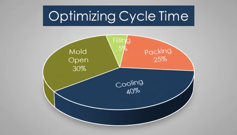
- De spuitgietcyclus omvat de fasen: injectie, nadrukken, koelen en uitwerpen.
- Koelen verbruikt doorgaans 50–80% van de totale cyclusduur.
- Cyclusduur bepaalt direct uw kosten per onderdeel en machinebenuttingsgraad.
- Wanddikte, matrijskoelontwerp en materiaalkeuze zijn de drie grootste hefbomen.
- Zelfs een verkorting van 2 seconden op een matrijs met veel holtes kan duizenden per maand besparen.
Wat is de spuitgietcyclus?
De spuitgietcyclus is de totale verstreken tijd vanaf het sluiten van de matrijs tot het uitwerpen van het onderdeel op een spuitgieten machine.
If you are comparing vendors or planning procurement, our injection molding supplier sourcing guide covers RFQ prep, qualification, and commercial risk checks.
Deze cyclus is belangrijk omdat hij uw doorvoerplafond bepaalt. Als uw cyclusduur 30 seconden is en u een 4-holtes matrijs gebruikt, produceert u 480 onderdelen per uur. Haal daar 5 seconden af, en u springt naar 576 onderdelen per uur – een capaciteitsverhoging van 20% zonder kapitaaluitgaven.
In onze fabriek in Shanghai hebben we 47 spuitgietmachines van 90T tot 1850T. Met meer dan 20 jaar productie-ervaring hebben we de cyclusduren voor duizenden matrijsprogramma's geoptimaliseerd. Ons technisch team houdt de cyclusduur van elke opdracht bij en werkt terug van de gewenste stuksprijs om de optimale cyclusparameters te bepalen.
In onze fabriek houden we de cyclusduur van elke opdracht bij. Wanneer een klant ons vraagt een bepaalde stuksprijs te halen, is het eerste getal waar we van terugrekenen de cyclusduur, omdat deze de machine-uurkosten per onderdeel bepaalt.
Wat zijn de vier fasen van de spuitgietcyclus?
De spuitgietcyclus bestaat uit vier fasen: inspuiten, nabranden, koelen en uitwerpen, elk bepaald door de geometrie van het onderdeel en het materiaal.
1. Injectie (Matrijsvulling)
Voor de meeste standaardonderdelen (wanddikte 2–3 mm, standaard kunststof) duurt het inspuiten van de holte 2–5 seconden. Grote constructieonderdelen met dikke wanden kunnen 8–12 seconden duren. Het inspuitsnelheidsprofiel wordt meestal in fasen geprogrammeerd—langzaam bij de ingang om straalvorming te voorkomen, snel door de hoofdholte, en dan weer langzaam aan het einde om overvulling te voorkomen.
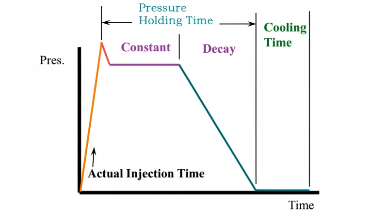
2. Nadrukken (Druk vasthouden)
Nadruktijd duurt meestal 5–30 seconden. Nadat de holte nominaal vol is, handhaaft de schroef druk om volumetrische krimp te compenseren terwijl het plastic afkoelt van smelttemperatuur naar stollingstemperatuur.
Deze fase voegt 5–25% meer materiaal toe aan de holte na de initiële vulling. De nadrukkingsdruk moet worden aangehouden totdat de ingang bevriest – zodra de ingang stolt, heeft extra druk geen effect meer op het onderdeel. Daarom zijn ingangsgrootte en -locatie kritieke ontwerpbeslissingen. Een ingang die te vroeg bevriest, leidt tot overmatige krimp; een die te laat bevriest, verlengt de cyclus onnodig.
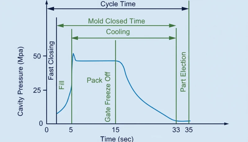
De optimale houdtijd wordt bepaald door onderdelen bij toenemende houdtijden te wegen totdat het onderdeelgewicht stabiliseert. Bij ZetarMold voeren we deze poortsluitingsstudie uit op elke nieuwe matrijs tijdens de T1-steekproef.
3. Koeling
Koelen is bijna altijd de langste fase en beslaat 50–80% van de totale cyclusduur. Typische koeltijden variëren van 10 tot 120 seconden, voornamelijk bepaald door wanddikte en het materiaal zijn thermal diffusivity1.
De vuistregel voor de koeltijd is ongeveer evenredig met het kwadraat van de wanddikte. Verdubbel de wanddikte, en de koeltijd verviervoudigt ongeveer. Daarom raden we vaak wanddikte-optimalisatie aan tijdens de DFM-beoordeling – van 4 mm naar 3 mm gaan in een niet-kritiek gebied kan de koeltijd met bijna 40% verminderen.
Het ontwerp van het koelkanaal is de meest invloedrijke technische beslissing voor de cyclusduur. conformal cooling channels2, die de contouren van het onderdeel volgen, kunnen de koeltijd met 20–40% verminderen in vergelijking met conventionele recht geboorde kanalen. Voor grootschalige productie kan dit alleen al de hogere gereedschapskosten rechtvaardigen.
4. Uitwerpen en matrijs openen
Uitwerptijd duurt doorgaans 2–10 seconden. Deze fase omvat het openen van de matrijs, het uitwerpen van het onderdeel (via uitwerppennen, stripperplaten of luchtstoten) en eventuele robot- of operatorverwijderingstijd, gevolgd door het sluiten van de matrijs voor de volgende cyclus.
Voor geautomatiseerde productie met robotmatige onderdeelverwijdering, reken op 3–6 seconden. Handmatige verwijdering voegt 1–3 seconden toe. De matrijsopeningsafstand, uitstootsnelheid en de aanwezigheid van zijacties (lifters, schuiven) beïnvloeden allemaal deze tijd.
De machinegrootte speelt ook een rol: een 80T-machine opent en sluit mogelijk in 4 seconden, terwijl een 1000T-machine 10–15 seconden nodig heeft voor dezelfde handeling vanwege een grotere plaatbeweging en zwaarder matrijsgewicht.
Hoe lang duurt een typische spuitgietcyclus?
Een typische spuitgietcyclus ligt tussen de 10 en 60 seconden voor de meeste productieonderdelen. Dunwandige verpakkingen kunnen onder de 5 seconden draaien, terwijl grote, dikwandige constructieonderdelen meer dan 120 seconden kunnen overschrijden.
| Onderdeeltype | Wanddikte | Typische cyclus | Belangrijkste knelpunt |
|---|---|---|---|
| Dunwandige verpakking | 0.5–1.0 mm | 3–8 seconden | Injectiesnelheid |
| Behuizing voor consumentenelektronica | 1.5–2.5 mm | 12–25 seconden | Koeltijd |
| Automotive interior | 2,0–3,5 mm | 20–45 seconds | Koeltijd |
| Medisch apparaatonderdeel | 1.0–3.0 mm | 15–35 seconden | Nadrukken + koelen |
| Groot constructieonderdeel | 4,0–8,0 mm | 60–120+ seconden | Koeltijd |
De bovenstaande tabel maakt één ding duidelijk: koelen domineert. Voor onderdelen met een wanddikte boven 2 mm is koelen waar u eerst op moet focussen bij optimalisatie-inspanningen.
Hoe berekent u de totale cyclusduur?
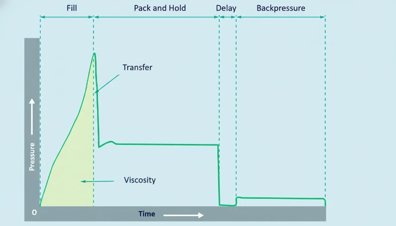
De totale cyclusduur is de som van inspuittijd, nawijltijd, koeltijd en matrijsopen-/sluit- plus uitstoottijd. In de praktijk overlapt schroefterugwinning (plasticering) met koelen, dus de effectieve cyclus wordt gedomineerd door de langste niet-overlappende fase.
The basic formula:
Cycle Time Formula:
Tcycle = Tinjectie + Tpacking + max(Tkoeling, Tscrew recovery) + Tmold open/close + Tejection
For quick estimation of injection time:
Injection Time Estimate:
Tinjectie = Vshot / (0.20–0.50 × Vmax) + tbase
As a practical example, consider a standard 3 mm wall-thickness PP housing produced on a 200T machine. Injection fills the cavity in about 3 seconds, packing holds for 8 seconds, cooling requires 18 seconds, and mold open/close plus ejection takes 5 seconds. Total cycle time: approximately 34 seconds per shot, yielding roughly 106 parts per hour from a single-cavity mold.
Welke factoren hebben de meeste invloed op de cyclusduur?
Wall thickness, mold cooling design, and material thermal properties have the largest impact on cycle time. Secondary factors include gate design, machine capability, and part ejection complexity.
Screw recovery time often overlaps with cooling and must be considered in the overall calculation. If the screw cannot fully recover (recharge) the next shot of molten material before the cooling stage finishes, recovery time becomes the bottleneck, extending total cycle time well beyond what the cooling calculation alone would suggest.
Wanddikte
Wall thickness is the single most influential factor because cooling time increases with the square of thickness. Reducing a 4 mm wall to 3 mm can cut cooling time by roughly 44%. This is why DFM feedback on wall thickness is not just a nice-to-have—it directly affects your per-part cost.
Mold Cooling Design
The number, diameter, and proximity of cooling channels to the cavity surface determine how quickly heat is extracted. A well-designed cooling circuit maintains a temperature differential between inlet and outlet water of less than 3°C. If your delta-T is 8°C, you have a cooling flow problem.
Materiaalkeuze
Crystalline polymers (PP, POM, PEEK) release latent heat of crystallization3 during solidification, extending cooling time by 30–50% compared to amorphous polymers (ABS, PC, PMMA) at equivalent wall thickness. Filled materials (glass-filled nylon, mineral-filled PP) conduct heat better and often cool faster.
For multi-cavity molds, runner layout also affects cycle time. A balanced runner system ensures all cavities fill and pack uniformly, preventing over-packed cavities from requiring excessive cooling. Unbalanced runners can force you to extend cooling time to accommodate the slowest-filling cavity.
Gate Design and Runner System
Advanced simulation tools (Moldflow, Moldex3D) can predict cycle time before steel is cut, allowing mold designers to optimize cooling layout and gate placement virtually. This reduces the number of physical iterations needed during sampling.
Gate size determines how long packing pressure is effective before gate freeze. A hot runner system eliminates runner waste and often reduces cycle time because there is no cold runner mass to cool and eject. Cold runner molds, especially three-plate designs, add both cooling and mold-opening time.
Machine Capability
Injection speed, clamp force, and platen speed all contribute. A modern servo-driven machine can open and close the mold 15–20% faster than a legacy hydraulic machine of the same tonnage. If your cycle is machine-limited, upgrading to a faster machine or a machine with better plasticizing capacity can be more cost-effective than mold modifications.
Hoe kunt u de cyclusduur verkorten zonder kwaliteit op te offeren?
The most effective ways to reduce cycle time are optimizing cooling channels, reducing wall thickness, and right-sizing gate seal time.
Optimize Cooling First
Since cooling accounts for 50–80% of cycle time, this is where the biggest gains live. Use thermal simulation (mold flow analysis) to identify hot spots before cutting steel. Consider conformal cooling channels for high-volume molds—they can reduce cooling time by 20–40%.
Ensure adequate coolant flow. The target is turbulent flow (Reynolds number > 4000) in every channel. If your shop uses tap water in summer without a chiller, water temperature rises and cooling efficiency drops significantly.
Right-Size the Packing Time
Many molders over-set packing time as a safety margin. Run a gate seal study: weigh parts at 5, 10, 15, 20 seconds of packing. When part weight stops increasing, you have found the minimum effective packing time. Anything beyond that is wasted time.
Use Robot Simultaneous Operations
If you use a robot for part removal, program it to begin extraction during mold opening rather than waiting for full opening. This can shave 1–3 seconds per cycle. On a high-cavity mold running 24/7, that is thousands of additional parts per month.
Consider Material Substitution
If the application allows, switching from a slow-cooling crystalline material to a faster-cooling amorphous alternative can reduce cycle time by 20–30%. For example, replacing POM with ABS in a non-critical bracket application. Always verify mechanical requirements before making this change.
Waar of onwaar: test uw kennis van de spuitgietcyclus?
““Cooling time accounts for the largest share of the injection molding cycle.””Echt
Cooling typically represents 50–80% of total cycle time. This is why cooling channel design has more impact on cycle reduction than any other single factor.
““Shorter cycle time always means lower per-part cost.””Vals
If you reduce cycle time by cutting cooling too short, you get warped parts, dimensional rejects, or stuck parts during ejection. The rework, scrap, and sorting costs can exceed the machine-time savings. Cycle optimization must maintain quality first.
Het begrijpen van deze veelvoorkomende misvattingen is essentieel voor iedereen die betrokken is bij productieplanning of matrijsontwerp. De volgende reeks uitspraken onderzoekt verder hoe beslissingen over cyclusduur interageren met materiaalgedrag, gereedschapsontwerp en praktische productiebeperkingen waar ingenieurs dagelijks op de fabrieksvloer mee te maken hebben.
Veel ervaren spuitgieters hebben situaties meegemaakt waarin de theorie uit het boekje en de praktijk op de werkvloer uiteenlopen. Een cyclus die op papier optimaal lijkt, kan inconsistente resultaten opleveren door variaties in materiaaleigenschappen per batch, schommelingen in de omgevingstemperatuur of subtiele veranderingen in de matrijs-oppervlakteconditie tijdens een lange productieserie. Dit is waarom continue monitoring en periodieke cyclusaudits standaardpraktijk blijven in goed geleide spuitgietbedrijven.
In hoogvolume productieomgevingen leveren zelfs kleine verbeteringen in cyclusduur snel samengestelde voordelen op. Een verkorting van twee seconden op een matrijs die 24 uur per dag draait, vertaalt zich in honderden extra onderdelen per week. Elke aanpassing moet echter worden gevalideerd met dimensionale gegevens en defecttracking voordat deze wordt vastgelegd in de standaardprocesparameters. Ervaring leert dat de veiligste optimalisaties eerst gericht zijn op koelrendement, gevolgd door verkorting van de naspuitijd en daarna verbeteringen van uitstootsnelheid.
“Hotrunnersystemen kunnen de cyclusduur verkorten door het koelen van de runner te elimineren.”Echt
Heetkanaalsystemen houden het plastic in het kanaalsysteem gesmolten tussen de schoten, dus er is geen koude kanaalmassa om te koelen en uit te werpen. Dit elimineert kanaalgerelateerde koel- en uitwerptijd en vermindert ook materiaalverspilling.
“Injectietijd is meestal de langste fase in de cyclus.”Vals
Injectietijd is typisch de kortste fase van 1–10 seconden. Koelen is de langste fase, vaak 50–80% van de totale cyclusduur. Injectiesnelheid is belangrijk voor onderdeelkwaliteit, maar domineert zelden de cyclusduur.
Wat Zijn de Meest Gestelde Vragen Over de Spuitgietcyclus?
Wat is de gemiddelde spuitgietcyclusduur?
De gemiddelde spuitgietcyclusduur voor productieonderdelen varieert van 15 tot 45 seconden. Dunwandige verpakkingen kunnen in minder dan 5 seconden worden geproduceerd, terwijl grote constructieonderdelen meer dan 120 seconden kunnen duren. Koeltijd is de dominante factor in de meeste cycli.
Hoe wordt de spuitgietcyclusduur berekend?
Cyclusduur = inspuitijd + naspuitijd + max(koeltijd, schroefhersteltijd) + matrijs openen/sluiten tijd + uitstoottijd. De max()-functie houdt rekening met de overlap tussen koelen en schroefherstel.
Welk percentage van de cyclusduur is koeling?
Afkoeling beslaat 50–80% van de totale spuitgietcyclusduur. Voor dikwandige onderdelen (4 mm+), kan afkoeling meer dan 80% van de totale cyclus bedragen.
Kun je de spuitgietcyclusduur verkorten nadat de matrijs is gebouwd?
Ja. Optimalisaties na de bouw omvatten het aanpassen van procesparameters (injectiesnelheid, naspuitijd, matrijstemperatuur), verbeteren van koelvloeistofstroming, toevoegen van externe koelinrichtingen en in sommige gevallen het aanpassen van koelkanalen of installeren van heetkanaalnozzles.
Beïnvloedt cyclusduur de onderdeelkwaliteit?
Ja. Onvoldoende koeltijd veroorzaakt vervorming, dimensionale instabiliteit en uitwerpsporen. Overmatige naspuitijd kan leiden tot overvulling en uitstulpingen. Elke fase moet geoptimaliseerd worden voor het materiaal en de onderdeelgeometrie.
Wat is het verschil tussen cycletijd en levertijd in spuitgieten?
Cyclusduur is het aantal seconden per schot op de machine (typisch 10–60 seconden). Doorlooptijd is de totale tijd van bestelling tot levering (typisch 4–12 weken), wat matrijsbouw, proefstukken, productieplanning en verzending omvat.
Hoe beïnvloedt de wanddikte de cyclusduur?
Koeltijd schaalt ongeveer met het kwadraat van de wanddikte. Het verdubbelen van de wanddikte verviervoudigt ruwweg de koeltijd. Dit is waarom optimalisatie van wanddikte tijdens DFM-beoordeling de meest impactvolle cyclusduurverlagingsstrategie is die beschikbaar is voordat de gereedschapsbouw begint.
Hulp nodig bij het optimaliseren van uw spuitgietcyclus?
Ons engineeringteam kan uw matrijsontwerp beoordelen voor cyclusoptimalisatie, een spuitgietstroomsimulatie uitvoeren en een gedetailleerde cyclusduurraming geven vóór het steken van staal. Met 45 machines (90T–1850T) en meer dan 20 jaar productie-ervaring hebben we de meeste uitdagingen op het gebied van cyclusduur gezien en opgelost.
Vraag een gratis offerte aan →
-
thermal diffusivityThermische diffusiviteit is een maat voor hoe snel warmte door een materiaal beweegt, gedefinieerd als thermische geleidbaarheid gedeeld door dichtheid en soortelijke warmtecapaciteit, gemeten in mm²/s. ↩
-
conformal cooling channels: conforme koelkanalen verwijst naar koelpassages in een matrijs die de contour van de onderdeelholte volgen, meestal vervaardigd via 3D-printen, wat een gelijkmatigere koeling biedt dan conventionele recht geboorde kanalen. ↩
-
latent heat of crystallizationLatente kristallisatiewarmte is de thermische energie die vrijkomt wanneer een kristallijne polymeer overgaat van een ongeordende smelttoestand naar een geordende kristallijne vaste toestand, meestal gemeten in J/g. ↩


