 Saltar para o conteúdo

Your production manager just asked why a simple cover part takes 45 seconds per shot when the competitor quoted 18. The answer almost always comes down to one thing: how well you understand—and optimize—the injection molding cycle.
The injection molding cycle is the complete sequence from mold close to part ejection. It is the single biggest driver of per-part cost in high-volume production. Get it wrong, and you burn profit on every cycle. Get it right, and you gain capacity without buying a single new machine.
- The injection molding cycle includes injection, packing, cooling, and ejection stages.
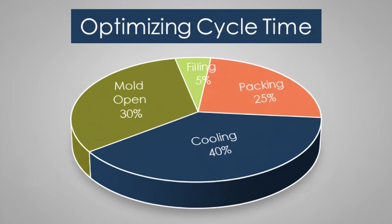
- Cooling typically consumes 50–80% of total cycle time.
- Cycle time directly sets your per-part cost and machine utilization rate.
- Wall thickness, mold cooling design, and material choice are the three biggest levers.
- Even a 2-second reduction on a high-cavity mold can save thousands per month.
What is the Injection Molding Cycle?
The injection molding cycle is the total elapsed time from mold close to part ejection on an moldagem por injeção máquina.
If you are comparing vendors or planning procurement, our injection molding supplier sourcing guide covers RFQ prep, qualification, and commercial risk checks.
This cycle matters because it sets your throughput ceiling. If your cycle time is 30 seconds and you run a 4-cavity mold, you produce 480 parts per hour. Shave 5 seconds off that cycle, and you jump to 576 parts per hour—a 20% capacity increase with zero capital expenditure.
In our Shanghai factory, we run 47 injection molding machines ranging from 90T to 1850T. With 20+ years of production experience, we have optimized cycle times across thousands of mold programs. Our engineering team tracks cycle time on every job, working backward from the target unit price to determine the optimal cycle parameters.
In our factory, we track cycle time on every job. When a customer asks us to hit a specific unit price, the first number we work backward from is the cycle time, because it determines machine-hour cost per part.
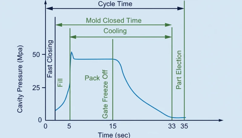
What are the Four Stages of the Injection Molding Cycle?
The injection molding cycle is composed of four stages: injection, packing, cooling, and ejection, each driven by part geometry and material.
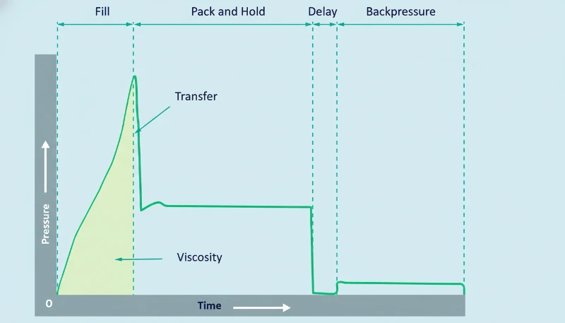
1. Injection (Mold Filling)
For most standard parts (wall thickness 2–3 mm, commodity resin), injection fills the cavity in 2–5 seconds. Large structural parts with thick walls can take 8–12 seconds. The injection speed profile is usually programmed in stages—slow at the gate to prevent jetting, fast through the main cavity, then slow again near the end to prevent overpacking.
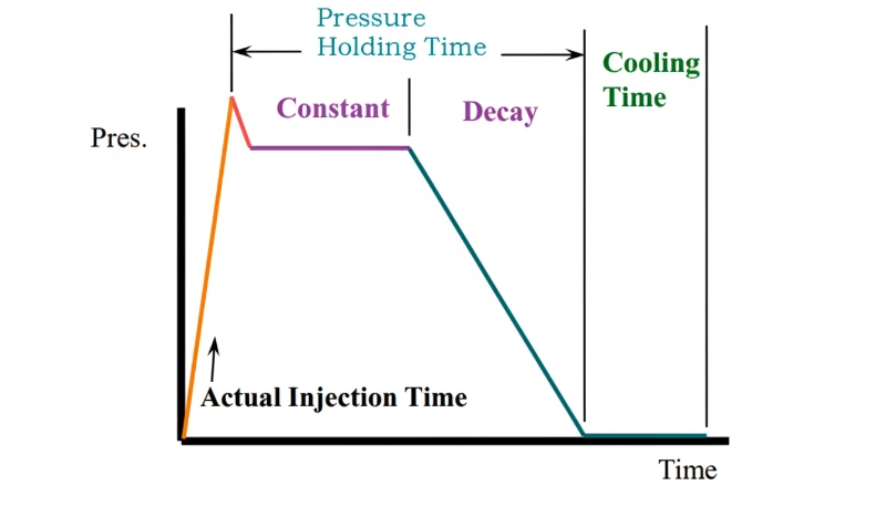
2. Packing (Holding Pressure)
Packing time usually runs 5–30 seconds. After the cavity is nominally full, the screw maintains pressure to compensate for volumetric shrinkage as the plastic cools from melt temperature to solidification temperature.
This stage adds 5–25% more material into the cavity after initial fill. The packing pressure must be held until the gate freezes—once the gate solidifies, additional pressure has no effect on the part. This is why gate size and location are critical design decisions. A gate that freezes too early leaves you with excessive shrinkage; one that freezes too late extends the cycle unnecessarily.
The optimal holding time is found by weighing parts at increasing hold times until part weight stabilizes. At ZetarMold, we run this gate seal study on every new mold during T1 sampling.
3. Arrefecimento
Cooling is almost always the longest stage, accounting for 50–80% of total cycle time. Typical cooling times range from 10 to 120 seconds, driven primarily by wall thickness and the material’s thermal diffusivity1.
The rule of thumb for cooling time is approximately proportional to the square of wall thickness. Double the wall thickness, and cooling time roughly quadruples. This is why we frequently recommend wall thickness optimization during DFM review—going from 4 mm to 3 mm in a non-critical area can cut cooling time by nearly 40%.
Cooling channel design is the most impactful engineering decision for cycle time. conformal cooling channels2, which follow the contour of the part, can reduce cooling time by 20–40% compared to conventional straight-drilled channels. For high-volume production, this alone can justify the higher tooling cost.
4. Ejection and Mold Opening
Ejection time typically takes 2\u201310 seconds. This stage includes mold opening, part ejection (via ejector pins, stripper plates, or air blasts), and any robot or operator removal time, followed by mold closing for the next cycle.
For automated production with robotic part removal, plan on 3\u20136 seconds. Manual removal adds 1\u20133 seconds. The mold opening distance, ejection stroke, and presence of side actions (lifters, sliders) all affect this time.
Machine size also plays a role: an 80T machine might open and close in 4 seconds, while a 1000T machine needs 10–15 seconds for the same action due to larger platen travel distance and heavier mold weight.
How Long Does a Typical Injection Molding Cycle Take?
A typical injection molding cycle is between 10 and 60 seconds for most production parts. Thin-wall packaging can run under 5 seconds, while large thick-wall structural parts may exceed 120 seconds.
| Tipo de peça | Espessura da parede | Typical Cycle | Key Bottleneck |
|---|---|---|---|
| Thin-wall packaging | 0.5–1.0 mm | 3–8 seconds | Velocidade de injeção |
| Consumer electronics housing | 1.5–2.5 mm | 12–25 seconds | Tempo de arrefecimento |
| Automotive interior | 2.0–3.5 mm | 20–45 seconds | Tempo de arrefecimento |
| Medical device component | 1.0–3.0 mm | 15–35 seconds | Packing + cooling |
| Large structural part | 4.0–8.0 mm | 60–120+ seconds | Tempo de arrefecimento |
The table above makes one thing obvious: cooling dominates. For parts above 2 mm wall thickness, cooling is where you should focus optimization efforts first.
How Do You Calculate Total Cycle Time?
Total cycle time is the sum of injection time, packing time, cooling time, and mold open/close plus ejection time. In practice, screw recovery (plasticization) overlaps with cooling, so the effective cycle is dominated by the longest non-overlapping stage.
The basic formula:
Cycle Time Formula:
Tcycle = Tinjeção + Tpacking + max(Tarrefecimento, Tscrew recovery) + Tmold open/close + Tejection
For quick estimation of injection time:
Injection Time Estimate:
Tinjeção = Vshot / (0.20–0.50 × Vmax) + tbase
As a practical example, consider a standard 3 mm wall-thickness PP housing produced on a 200T machine. Injection fills the cavity in about 3 seconds, packing holds for 8 seconds, cooling requires 18 seconds, and mold open/close plus ejection takes 5 seconds. Total cycle time: approximately 34 seconds per shot, yielding roughly 106 parts per hour from a single-cavity mold.
What Factors Affect Cycle Time the Most?
Wall thickness, mold cooling design, and material thermal properties have the largest impact on cycle time. Secondary factors include gate design, machine capability, and part ejection complexity.
Screw recovery time often overlaps with cooling and must be considered in the overall calculation. If the screw cannot fully recover (recharge) the next shot of molten material before the cooling stage finishes, recovery time becomes the bottleneck, extending total cycle time well beyond what the cooling calculation alone would suggest.
Espessura da parede
Wall thickness is the single most influential factor because cooling time increases with the square of thickness. Reducing a 4 mm wall to 3 mm can cut cooling time by roughly 44%. This is why DFM feedback on wall thickness is not just a nice-to-have—it directly affects your per-part cost.
Mold Cooling Design
The number, diameter, and proximity of cooling channels to the cavity surface determine how quickly heat is extracted. A well-designed cooling circuit maintains a temperature differential between inlet and outlet water of less than 3°C. If your delta-T is 8°C, you have a cooling flow problem.
Seleção de materiais
Crystalline polymers (PP, POM, PEEK) release latent heat of crystallization3 during solidification, extending cooling time by 30–50% compared to amorphous polymers (ABS, PC, PMMA) at equivalent wall thickness. Filled materials (glass-filled nylon, mineral-filled PP) conduct heat better and often cool faster.
For multi-cavity molds, runner layout also affects cycle time. A balanced runner system ensures all cavities fill and pack uniformly, preventing over-packed cavities from requiring excessive cooling. Unbalanced runners can force you to extend cooling time to accommodate the slowest-filling cavity.
Gate Design and Runner System
Advanced simulation tools (Moldflow, Moldex3D) can predict cycle time before steel is cut, allowing mold designers to optimize cooling layout and gate placement virtually. This reduces the number of physical iterations needed during sampling.
Gate size determines how long packing pressure is effective before gate freeze. A hot runner system eliminates runner waste and often reduces cycle time because there is no cold runner mass to cool and eject. Cold runner molds, especially three-plate designs, add both cooling and mold-opening time.
Machine Capability
Injection speed, clamp force, and platen speed all contribute. A modern servo-driven machine can open and close the mold 15–20% faster than a legacy hydraulic machine of the same tonnage. If your cycle is machine-limited, upgrading to a faster machine or a machine with better plasticizing capacity can be more cost-effective than mold modifications.
How Can You Reduce Cycle Time Without Sacrificing Quality?
The most effective ways to reduce cycle time are optimizing cooling channels, reducing wall thickness, and right-sizing gate seal time.
Optimize Cooling First
Since cooling accounts for 50–80% of cycle time, this is where the biggest gains live. Use thermal simulation (mold flow analysis) to identify hot spots before cutting steel. Consider conformal cooling channels for high-volume molds—they can reduce cooling time by 20–40%.
Ensure adequate coolant flow. The target is turbulent flow (Reynolds number > 4000) in every channel. If your shop uses tap water in summer without a chiller, water temperature rises and cooling efficiency drops significantly.
Right-Size the Packing Time
Many molders over-set packing time as a safety margin. Run a gate seal study: weigh parts at 5, 10, 15, 20 seconds of packing. When part weight stops increasing, you have found the minimum effective packing time. Anything beyond that is wasted time.
Use Robot Simultaneous Operations
If you use a robot for part removal, program it to begin extraction during mold opening rather than waiting for full opening. This can shave 1–3 seconds per cycle. On a high-cavity mold running 24/7, that is thousands of additional parts per month.
Consider Material Substitution
If the application allows, switching from a slow-cooling crystalline material to a faster-cooling amorphous alternative can reduce cycle time by 20–30%. For example, replacing POM with ABS in a non-critical bracket application. Always verify mechanical requirements before making this change.
True or False: Test Your Injection Molding Cycle Knowledge?
““Cooling time accounts for the largest share of the injection molding cycle.””Verdadeiro
Cooling typically represents 50–80% of total cycle time. This is why cooling channel design has more impact on cycle reduction than any other single factor.
““Shorter cycle time always means lower per-part cost.””Falso
Se reduzir o tempo de ciclo cortando o arrefecimento demasiado cedo, obtém peças deformadas, rejeições dimensionais ou peças presas durante a ejeção. Os custos de retrabalho, sucata e triagem podem exceder a poupança de tempo de máquina. A otimização do ciclo deve manter a qualidade em primeiro lugar.
Compreender estes equívocos comuns é essencial para qualquer pessoa envolvida no planeamento da produção ou conceção do molde. O próximo conjunto de afirmações explora ainda mais como as decisões sobre o tempo de ciclo interagem com o comportamento do material, o design do molde e as restrições de produção do mundo real que os engenheiros enfrentam diariamente na fábrica.
Muitos moldadores experientes já se depararam com situações em que a teoria dos manuais e a realidade da oficina divergem. Um ciclo que parece ótimo no papel pode produzir resultados inconsistentes devido a variações nas propriedades do lote de material, mudanças na temperatura ambiente ou alterações subtis na condição da superfície do molde ao longo de uma longa produção. É por isso que a monitorização contínua e as auditorias periódicas ao ciclo continuam a ser uma prática padrão em instalações de moldagem bem geridas.
Em ambientes de produção de alto volume, mesmo pequenas melhorias no tempo de ciclo acumulam-se rapidamente. Uma redução de dois segundos num molde a funcionar 24 horas por dia traduz-se em centenas de peças adicionais por semana. No entanto, qualquer ajuste deve ser validado com dados dimensionais e rastreamento de defeitos antes de ser bloqueado nos parâmetros padrão do processo. A experiência mostra que as otimizações mais seguras visam primeiro a eficiência do arrefecimento, seguidas da redução do tempo de compactação e depois das melhorias na velocidade de ejeção.
““Os sistemas de canais quentes podem reduzir o tempo de ciclo ao eliminar o arrefecimento dos canais.””Verdadeiro
Os canais quentes mantêm o plástico no sistema de canais fundido entre os disparos, pelo que não há massa de canal fria para arrefecer e ejetar. Isto elimina o tempo de arrefecimento e ejeção relacionados com os canais e também reduz o desperdício de material.
“O tempo de injeção é geralmente a etapa mais longa do ciclo.”Falso
O tempo de injeção é tipicamente a fase mais curta, com 1–10 segundos. O arrefecimento é a fase mais longa, frequentemente 50–80% do tempo total do ciclo. A velocidade de injeção é importante para a qualidade da peça, mas raramente domina a duração do ciclo.
What Are the Most Frequently Asked Questions About the Injection Molding Cycle?
Qual é o tempo médio do ciclo de moldagem por injeção?
O tempo médio de ciclo de moldagem por injeção para peças de produção varia entre 15 e 45 segundos. As embalagens de parede fina podem funcionar em menos de 5 segundos, enquanto as peças estruturais grandes podem exceder 120 segundos. O tempo de arrefecimento é o fator dominante na maioria dos ciclos.
Como é calculado o tempo de ciclo de moldagem por injeção?
Tempo de ciclo = tempo de injeção + tempo de compactação + máximo(tempo de arrefecimento, tempo de recuperação da rosca) + tempo de abertura/fecho do molde + tempo de ejeção. A função máximo() tem em conta a sobreposição entre o arrefecimento e a recuperação da rosca.
Que percentagem do tempo de ciclo é arrefecimento?
O arrefecimento representa 50–80% do tempo total do ciclo de moldagem por injeção. Para peças de parede espessa (4 mm+), o arrefecimento pode exceder 80% do ciclo total.
Pode reduzir o tempo de ciclo de moldagem por injeção após a construção do molde?
Sim. As otimizações pós-construção incluem ajustar parâmetros do processo (velocidade de injeção, tempo de embalagem, temperatura do molde), melhorar o fluxo do refrigerante, adicionar dispositivos de arrefecimento externos e, em alguns casos, remodelar canais de arrefecimento ou instalar bicos de distribuidor quente.
O tempo de ciclo afeta a qualidade da peça?
Sim. Tempo de arrefecimento insuficiente causa empenamento, instabilidade dimensional e marcas de ejeção. Tempo de embalagem excessivo pode causar sobrecarga e rebarbas. Cada etapa deve ser otimizada de acordo com os requisitos do material e da geometria da peça.
Qual é a diferença entre o tempo de ciclo e o tempo de entrega na moldagem por injeção?
O tempo de ciclo são os segundos por disparo na máquina (tipicamente 10–60 segundos). O lead time é o tempo total desde a encomenda até à entrega (tipicamente 4–12 semanas), que inclui a construção do molde, amostragem, planeamento da produção e expedição.
Como é que a espessura da parede afeta o tempo de ciclo?
O tempo de arrefecimento escala aproximadamente com o quadrado da espessura da parede. Duplicar a espessura da parede quadruplica aproximadamente o tempo de arrefecimento. É por isso que a otimização da espessura da parede durante a revisão do DFM é a estratégia de redução do tempo de ciclo mais impactante disponível antes do início do molde.
Precisa de Ajuda para Otimizar o Seu Ciclo de Moldagem por Injeção?
A nossa equipa de engenharia pode rever o seu projeto de molde para otimização do ciclo, executar simulação de fluxo de molde e fornecer uma estimativa detalhada do tempo de ciclo antes do corte do aço. Com 45 máquinas (90T–1850T) e mais de 20 anos de experiência em produção, já vimos—e resolvemos—a maioria dos desafios de tempo de ciclo.
Get a Free Quote →
-
thermal diffusivity: A difusividade térmica é uma medida da rapidez com que o calor se move através de um material, definida como a condutividade térmica dividida pela densidade e capacidade térmica específica, medida em mm2/s. ↩
-
conformal cooling channels: canais de arrefecimento conformes referem-se a passagens de arrefecimento num molde que seguem o contorno da cavidade da peça, tipicamente fabricados via impressão 3D, proporcionando um arrefecimento mais uniforme do que os canais retos perfurados convencionalmente. ↩
-
latent heat of crystallization: O calor latente de cristalização é a energia térmica libertada quando um polímero cristalino transita de um estado de fusão desordenado para um estado sólido cristalino ordenado, tipicamente medido em J/g. ↩


