 İçeriğe geç

Your production manager just asked why a simple cover part takes 45 seconds per shot when the competitor quoted 18. The answer almost always comes down to one thing: how well you understand—and optimize—the injection molding cycle.
The injection molding cycle is the complete sequence from mold close to part ejection. It is the single biggest driver of per-part cost in high-volume production. Get it wrong, and you burn profit on every cycle. Get it right, and you gain capacity without buying a single new machine.
- The injection molding cycle includes injection, packing, cooling, and ejection stages.
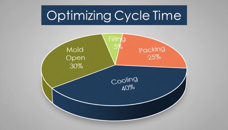
- Cooling typically consumes 50–80% of total cycle time.
- Cycle time directly sets your per-part cost and machine utilization rate.
- Wall thickness, mold cooling design, and material choice are the three biggest levers.
- Even a 2-second reduction on a high-cavity mold can save thousands per month.
What is the Injection Molding Cycle?
The injection molding cycle is the total elapsed time from mold close to part ejection on an enjeksiyon kalıplama Makine.
If you are comparing vendors or planning procurement, our injection molding supplier sourcing guide covers RFQ prep, qualification, and commercial risk checks.
This cycle matters because it sets your throughput ceiling. If your cycle time is 30 seconds and you run a 4-cavity mold, you produce 480 parts per hour. Shave 5 seconds off that cycle, and you jump to 576 parts per hour—a 20% capacity increase with zero capital expenditure.
In our Shanghai factory, we run 47 injection molding machines ranging from 90T to 1850T. With 20+ years of production experience, we have optimized cycle times across thousands of mold programs. Our engineering team tracks cycle time on every job, working backward from the target unit price to determine the optimal cycle parameters.
In our factory, we track cycle time on every job. When a customer asks us to hit a specific unit price, the first number we work backward from is the cycle time, because it determines machine-hour cost per part.
What are the Four Stages of the Injection Molding Cycle?
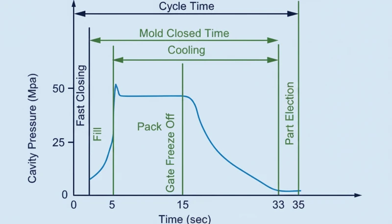
The injection molding cycle is composed of four stages: injection, packing, cooling, and ejection, each driven by part geometry and material.
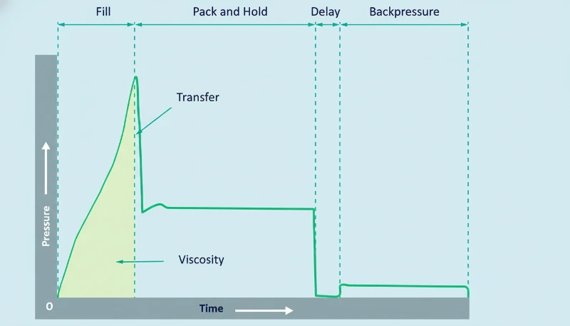
1. Injection (Mold Filling)
For most standard parts (wall thickness 2–3 mm, commodity resin), injection fills the cavity in 2–5 seconds. Large structural parts with thick walls can take 8–12 seconds. The injection speed profile is usually programmed in stages—slow at the gate to prevent jetting, fast through the main cavity, then slow again near the end to prevent overpacking.
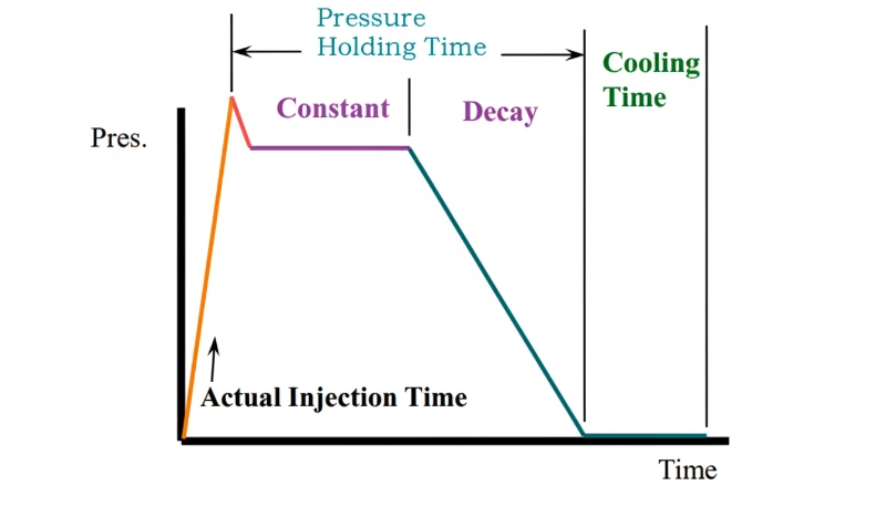
2. Packing (Holding Pressure)
Packing time usually runs 5–30 seconds. After the cavity is nominally full, the screw maintains pressure to compensate for volumetric shrinkage as the plastic cools from melt temperature to solidification temperature.
This stage adds 5–25% more material into the cavity after initial fill. The packing pressure must be held until the gate freezes—once the gate solidifies, additional pressure has no effect on the part. This is why gate size and location are critical design decisions. A gate that freezes too early leaves you with excessive shrinkage; one that freezes too late extends the cycle unnecessarily.
The optimal holding time is found by weighing parts at increasing hold times until part weight stabilizes. At ZetarMold, we run this gate seal study on every new mold during T1 sampling.
3. Soğutma
Cooling is almost always the longest stage, accounting for 50–80% of total cycle time. Typical cooling times range from 10 to 120 seconds, driven primarily by wall thickness and the material’s thermal diffusivity1.
The rule of thumb for cooling time is approximately proportional to the square of wall thickness. Double the wall thickness, and cooling time roughly quadruples. This is why we frequently recommend wall thickness optimization during DFM review—going from 4 mm to 3 mm in a non-critical area can cut cooling time by nearly 40%.
Cooling channel design is the most impactful engineering decision for cycle time. conformal cooling channels2, which follow the contour of the part, can reduce cooling time by 20–40% compared to conventional straight-drilled channels. For high-volume production, this alone can justify the higher tooling cost.
4. Ejection and Mold Opening
Ejection time typically takes 2\u201310 seconds. This stage includes mold opening, part ejection (via ejector pins, stripper plates, or air blasts), and any robot or operator removal time, followed by mold closing for the next cycle.
For automated production with robotic part removal, plan on 3\u20136 seconds. Manual removal adds 1\u20133 seconds. The mold opening distance, ejection stroke, and presence of side actions (lifters, sliders) all affect this time.
Machine size also plays a role: an 80T machine might open and close in 4 seconds, while a 1000T machine needs 10–15 seconds for the same action due to larger platen travel distance and heavier mold weight.
How Long Does a Typical Injection Molding Cycle Take?
A typical injection molding cycle is between 10 and 60 seconds for most production parts. Thin-wall packaging can run under 5 seconds, while large thick-wall structural parts may exceed 120 seconds.
| Parça Tipi | Duvar Kalınlığı | Typical Cycle | Key Bottleneck |
|---|---|---|---|
| Thin-wall packaging | 0.5–1.0 mm | 3–8 seconds | Enjeksiyon hızı |
| Consumer electronics housing | 1.5–2.5 mm | 12–25 seconds | Soğutma süresi |
| Automotive interior | 2.0–3.5 mm | 20–45 seconds | Soğutma süresi |
| Medical device component | 1.0–3.0 mm | 15–35 seconds | Packing + cooling |
| Large structural part | 4.0–8.0 mm | 60–120+ seconds | Soğutma süresi |
The table above makes one thing obvious: cooling dominates. For parts above 2 mm wall thickness, cooling is where you should focus optimization efforts first.
How Do You Calculate Total Cycle Time?
Total cycle time is the sum of injection time, packing time, cooling time, and mold open/close plus ejection time. In practice, screw recovery (plasticization) overlaps with cooling, so the effective cycle is dominated by the longest non-overlapping stage.
The basic formula:
Cycle Time Formula:
Tcycle = Tenjeksiyon + Tpacking + max(Tsoğutma, Tscrew recovery) + Tmold open/close + Tejection
For quick estimation of injection time:
Injection Time Estimate:
Tenjeksiyon = Vshot / (0.20–0.50 × Vmax) + tbase
As a practical example, consider a standard 3 mm wall-thickness PP housing produced on a 200T machine. Injection fills the cavity in about 3 seconds, packing holds for 8 seconds, cooling requires 18 seconds, and mold open/close plus ejection takes 5 seconds. Total cycle time: approximately 34 seconds per shot, yielding roughly 106 parts per hour from a single-cavity mold.
What Factors Affect Cycle Time the Most?
Wall thickness, mold cooling design, and material thermal properties have the largest impact on cycle time. Secondary factors include gate design, machine capability, and part ejection complexity.
Screw recovery time often overlaps with cooling and must be considered in the overall calculation. If the screw cannot fully recover (recharge) the next shot of molten material before the cooling stage finishes, recovery time becomes the bottleneck, extending total cycle time well beyond what the cooling calculation alone would suggest.
Duvar Kalınlığı
Wall thickness is the single most influential factor because cooling time increases with the square of thickness. Reducing a 4 mm wall to 3 mm can cut cooling time by roughly 44%. This is why DFM feedback on wall thickness is not just a nice-to-have—it directly affects your per-part cost.
Mold Cooling Design
The number, diameter, and proximity of cooling channels to the cavity surface determine how quickly heat is extracted. A well-designed cooling circuit maintains a temperature differential between inlet and outlet water of less than 3°C. If your delta-T is 8°C, you have a cooling flow problem.
Malzeme Seçimi
Crystalline polymers (PP, POM, PEEK) release latent heat of crystallization3 during solidification, extending cooling time by 30–50% compared to amorphous polymers (ABS, PC, PMMA) at equivalent wall thickness. Filled materials (glass-filled nylon, mineral-filled PP) conduct heat better and often cool faster.
For multi-cavity molds, runner layout also affects cycle time. A balanced runner system ensures all cavities fill and pack uniformly, preventing over-packed cavities from requiring excessive cooling. Unbalanced runners can force you to extend cooling time to accommodate the slowest-filling cavity.
Gate Design and Runner System
Advanced simulation tools (Moldflow, Moldex3D) can predict cycle time before steel is cut, allowing mold designers to optimize cooling layout and gate placement virtually. This reduces the number of physical iterations needed during sampling.
Gate size determines how long packing pressure is effective before gate freeze. A hot runner system eliminates runner waste and often reduces cycle time because there is no cold runner mass to cool and eject. Cold runner molds, especially three-plate designs, add both cooling and mold-opening time.
Machine Capability
Injection speed, clamp force, and platen speed all contribute. A modern servo-driven machine can open and close the mold 15–20% faster than a legacy hydraulic machine of the same tonnage. If your cycle is machine-limited, upgrading to a faster machine or a machine with better plasticizing capacity can be more cost-effective than mold modifications.
How Can You Reduce Cycle Time Without Sacrificing Quality?
The most effective ways to reduce cycle time are optimizing cooling channels, reducing wall thickness, and right-sizing gate seal time.
Optimize Cooling First
Since cooling accounts for 50–80% of cycle time, this is where the biggest gains live. Use thermal simulation (mold flow analysis) to identify hot spots before cutting steel. Consider conformal cooling channels for high-volume molds—they can reduce cooling time by 20–40%.
Ensure adequate coolant flow. The target is turbulent flow (Reynolds number > 4000) in every channel. If your shop uses tap water in summer without a chiller, water temperature rises and cooling efficiency drops significantly.
Right-Size the Packing Time
Many molders over-set packing time as a safety margin. Run a gate seal study: weigh parts at 5, 10, 15, 20 seconds of packing. When part weight stops increasing, you have found the minimum effective packing time. Anything beyond that is wasted time.
Use Robot Simultaneous Operations
If you use a robot for part removal, program it to begin extraction during mold opening rather than waiting for full opening. This can shave 1–3 seconds per cycle. On a high-cavity mold running 24/7, that is thousands of additional parts per month.
Consider Material Substitution
If the application allows, switching from a slow-cooling crystalline material to a faster-cooling amorphous alternative can reduce cycle time by 20–30%. For example, replacing POM with ABS in a non-critical bracket application. Always verify mechanical requirements before making this change.
True or False: Test Your Injection Molding Cycle Knowledge?
““Cooling time accounts for the largest share of the injection molding cycle.””Doğru
Cooling typically represents 50–80% of total cycle time. This is why cooling channel design has more impact on cycle reduction than any other single factor.
““Shorter cycle time always means lower per-part cost.””Yanlış
If you reduce cycle time by cutting cooling too short, you get warped parts, dimensional rejects, or stuck parts during ejection. The rework, scrap, and sorting costs can exceed the machine-time savings. Cycle optimization must maintain quality first.
Understanding these common misconceptions is essential for anyone involved in production planning or kalıp tasarımı. The next set of statements further explores how cycle time decisions interact with material behavior, tooling design, and real-world production constraints that engineers face on the factory floor every day.
Many experienced molders have encountered situations where textbook theory and shop-floor reality diverge. A cycle that looks optimal on paper may produce inconsistent results due to variations in material batch properties, ambient temperature shifts, or subtle changes in mold surface condition over a long production run. This is why continuous monitoring and periodic cycle audits remain standard practice in well-run molding facilities.
In high-volume production environments, even small cycle time improvements compound quickly. A two-second reduction on a mold running 24 hours a day translates to hundreds of additional parts per week. However, any adjustment must be validated with dimensional data and defect tracking before being locked into the standard process parameters. Experience shows that the safest optimizations target cooling efficiency first, followed by packing time reduction, and then ejection speed improvements.
““Hot runner systems can reduce cycle time by eliminating runner cooling.””Doğru
Hot runners keep the plastic in the runner system molten between shots, so there is no cold runner mass to cool and eject. This eliminates runner-related cooling and ejection time, and also reduces material waste.
“Injection time is usually the longest stage in the cycle.”Yanlış
Injection time is typically the shortest stage at 1–10 seconds. Cooling is the longest stage, often 50–80% of total cycle time. Injection speed is important for part quality, but it rarely dominates cycle duration.
What Are the Most Frequently Asked Questions About the Injection Molding Cycle?
What is the average injection molding cycle time?
The average injection molding cycle time for production parts ranges from 15 to 45 seconds. Thin-wall packaging can run under 5 seconds, while large structural parts may exceed 120 seconds. Cooling time is the dominant factor in most cycles.
How is injection molding cycle time calculated?
Cycle time = injection time + packing time + max(cooling time, screw recovery time) + mold open/close time + ejection time. The max() function accounts for the overlap between cooling and screw recovery.
What percentage of cycle time is cooling?
Cooling accounts for 50–80% of total injection molding cycle time. For thick-wall parts (4 mm+), cooling can exceed 80% of the total cycle.
Can you reduce injection molding cycle time after the mold is built?
Yes. Post-build optimizations include adjusting process parameters (injection speed, packing time, mold temperature), improving coolant flow, adding external cooling fixtures, and in some cases, retrofitting cooling channels or installing hot runner nozzles.
Does cycle time affect part quality?
Yes. Insufficient cooling time causes warpage, dimensional instability, and ejection marks. Excessive packing time can cause overpacking and flash. Each stage must be optimized to the material and part geometry requirements.
Enjeksiyon kalıplamada döngü süresi ile teslim süresi arasındaki fark nedir?
Cycle time is the seconds per shot on the machine (typically 10–60 seconds). Lead time is the total time from order to delivery (typically 4–12 weeks), which includes mold building, sampling, production scheduling, and shipping.
Duvar kalınlığı döngü süresini nasıl etkiler?
Cooling time scales approximately with the square of wall thickness. Doubling wall thickness roughly quadruples cooling time. This is why wall thickness optimization during DFM review is the most impactful cycle-time reduction strategy available before tooling begins.
Need Help Optimizing Your Injection Molding Cycle?
Our engineering team can review your mold design for cycle optimization, run mold flow simulation, and provide a detailed cycle time estimate before steel cutting. With 45 machines (90T–1850T) and 20+ years of production experience, we have seen—and solved—most cycle-time challenges.
Get a Free Quote →
-
thermal diffusivity: Thermal diffusivity is a measure of how quickly heat moves through a material, defined as thermal conductivity divided by density and specific heat capacity, measured in mm2/s. ↩
-
conformal cooling channels: conformal cooling channels refers to are cooling passages in a mold that follow the contour of the part cavity, typically manufactured via 3D printing, providing more uniform cooling than conventional straight-drilled channels. ↩
-
latent heat of crystallization: Latent heat of crystallization is the thermal energy released when a crystalline polymer transitions from a disordered melt state to an ordered crystalline solid state, typically measured in J/g. ↩


