 İçeriğe geç

Duvar kalınlığı[1] enjeksiyon kalıplamada tartışmasız en önemli tasarım parametresidir. Doğru yaparsanız, parçanız temiz kalıplanır, güvenilir çalışır ve daha az maliyetli olur. Yanlış yaparsanız, çökme izleri, eğilme, boşluklar ve kar marjınızı tüketen döngü süreleriyle uğraşırsınız.
Key Takeaways:
- Çoğu mühendislik termoplastiği için nominal duvar kalınlığını 1,5–3,0 mm arasında tutun.
- Parça boyunca duvar değişimini nominal değerin ±'i içinde tutun.
- Farklı duvar kalınlıkları arasındaki geçişler için 3:1 koniklik oranını kullanın.
- Çökme izlerini önlemek için kaburga taban kalınlığını nominal duvarın –60'ında tutun.
- Soğuma süresi duvar kalınlığının karesiyle ölçeklenir — ince duvar tasarımı yüksek ROI'ye sahiptir.
Bu kılavuz, mühendislerin bilmesi gereken her şeyi kapsar enjeksiyon kalıplama duvar kalınlığı: doğru değeri nasıl seçeceğiniz, duvarlar düzgün olmadığında ne olduğu, malzemeye özgü kılavuzlar ve binlerce DFM incelemesinden en yaygın hatalar.
Enjeksiyon Kalıplamada Duvar Kalınlığı Nedir?
Duvar kalınlığı, bir kalıplanmış parçanın herhangi bir kesitindeki dış ve iç yüzey arasındaki mesafedir. Plastik enjeksiyon kalıp boşluğundan nasıl akacağını, parçanın ne kadar hızlı soğuyacağını ve nihai boyutların spesifikasyona uyup uymayacağını belirler.
“Duvar kalınlığı varyasyonu nominal değerin ±'i içinde kalmalıdır.”Doğru
Endüstri kılavuzu ± varyasyondur. Kademeli geçişler olmadan bunu aşmak, farklı büzülme, eğilme ve boyutsal kararsızlığa neden olur.
“Tabana eşit kalınlıkta, nominal duvarın 'i olan bir kaburga çökme izine neden olmaz.”Yanlış
Nominal duvarın –60'ından daha kalın kaburgalar, neredeyse her zaman görünür çökme izleri üretir çünkü kaburga, çevreleyen duvardan çok daha yavaş soğuyan lokalize bir sıcak nokta yaratır.
Daha ince duvarlar malzeme tasarrufu sağlar ve döngü süresini azaltır, ancak enjeksiyon basıncı gereksinimlerini artırır ve kısa dolum riskini yükseltir. Daha kalın duvarlar daha kolay akar ancak yavaş soğur, döngü süresini uzatır ve boşluk ile çökme izi riskini artırır. Çoğu mühendislik termoplastiği için ideal aralık 1,5–3,0 mm'dir. Tasarımı sonuçlandırmadan önce seçtiğiniz kalınlığı her zaman malzeme tedarikçisinin veri sayfası ve akış simülasyon sonuçlarıyla doğrulayın.
Neden Düzgün Duvar Kalınlığı Bu Kadar Önemli?
Düzensiz duvar kalınlığı, diğer tüm tasarım hatalarından daha fazla kalıplama kusurunun temel nedenidir. Duvarlar önemli ölçüde değiştiğinde, kalın bölümler ince bölümlere göre farklı bir hızda soğur ve büzülür. Bu farklı büzülmeenjeksiyon kalıplama[2] eğrilme, çökme izleri ve boyutsal kararsızlık olarak ortaya çıkan iç gerilimler yaratır.
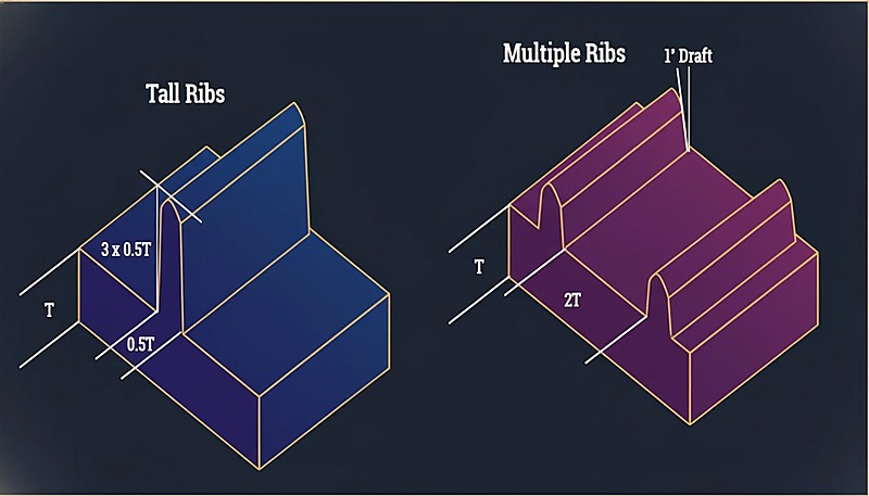
“Sertlik için genellikle birden fazla ince kaburga, tek bir yüksek ve kalın kaburgadan daha iyidir.”Doğru
Birden fazla ince nervür, yerelleştirilmiş bir termal kütle oluşturan tek bir kalın nervüre kıyasla stresi eşit şekilde dağıtır, daha hızlı soğur ve minimum çökme izi üretir.
“İnce bölüm kısa ise, 3 mm'den 1,5 mm duvara keskin 90° geçiş kabul edilebilir.”Yanlış
Ani geçişler, uzunluktan bağımsız olarak gerilim yoğunlaşmaları yaratır. Akış tereddüdüne, artık gerilimin artmasına ve görünür yüzey kusurlarına neden olurlar. Her zaman 3:1 koniklik oranını kullanın.
Kılavuz basittir: tüm parça boyunca duvar kalınlığını nominal değerin ±'i içinde tutun. Nominal duvarınız 2,5 mm ise, her bölüm 1,9 mm ile 3,1 mm arasında olmalıdır.
Malzemeye Göre Önerilen Duvar Kalınlığı Nedir?
Farklı malzemelerin farklı akış özellikleri ve büzülme oranları vardır. İşte kapsamlı üretim verilerine dayanan pratik bir referans tablosu.
| Malzeme | Min Wall (mm) | İdeal Aralık (mm) | Maks. Pratik (mm) |
|---|---|---|---|
| ABS | 0.8 | 1.5–3.0 | 4.5 |
| PC (Polikarbonat) | 0.8 | 1.5–3.0 | 4.5 |
| PP (Polipropilen) | 0.6 | 1.2–2.5 | 5.0 |
| PA (Naylon 6/66) | 0.6 | 1.0–3.0 | 4.0 |
| POM (Acetal) | 0.8 | 1.0–3.0 | 4.0 |
| PMMA (Acrylic) | 0.8 | 1,5–3,5 | 5.0 |
| PBT | 0.8 | 1.0–3.0 | 4.0 |
| PE (Polietilen) | 0.6 | 1.0–2.5 | 5.0 |
| PS (Polistiren) | 0.8 | 1.0–3.0 | 4.5 |
| TPE/TPU | 0.5 | 1.0–3.0 | 5.0 |
Minimum duvar değerleri, optimize edilmiş işlemeyle teknik olarak mümkün olanı temsil eder, üretim için önerileni değil. Güvenilir üretim için ideal aralıkta kalın.
Farklı Duvar Kalınlıkları Arasında Nasıl Geçiş Yapılır?
Bazen duvar kalınlığı değişimi kaçınılmazdır. Bu olduğunda, kalın ve ince bölümler arasındaki geçiş kritiktir. Standart kılavuz, 3:1 koniklik oranıdır: her 1 mm kalınlık değişimi için en az 3 mm kademeli geçiş sağlayın.
Ani kalınlık değişimleri akış tereddüdüne, gerilim yoğunlaşmalarına ve karşı yüzeyde görünür çökme izlerine neden olur. Ağır durumlarda, parçalar montaj sırasında kalınlık geçişlerinde kırılır çünkü artık gerilim malzemenin akma mukavemetini aşar.
Duvarlar Çok Kalın Olduğunda Ne Olur?
Kalın duvarlar üç sorun yaratır: aşırı döngü süresi, iç boşluklar ve çökme izleri.
Cycle Time Penalty
Soğuma süresi yaklaşık olarak duvar kalınlığının karesiyle ölçeklenir. 2 mm duvarlı bir parça 15 saniyede soğuyabilir; aynı geometriye sahip 4 mm duvarlı bir parça 50–60 saniye alabilir. 100.000 parçalık bir üretim serisinde, bu binlerce ek makine saati demektir.
“Soğuma süresi duvar kalınlığının karesiyle ölçeklenir — duvarı iki katına çıkarmak soğuma süresini dört katına çıkarır.”Doğru
Bu doğrusal olmayan ilişki, ince duvar tasarımının neden bu kadar yüksek ROI'ye sahip olduğunu açıklar. Duvarı 4mm'den 2mm'ye düşürmek, soğuma süresini oranında azaltabilir.
“Duvar kalınlığını azaltmak her zaman parça kalitesini ve üretim verimliliğini iyileştirir.”Yanlış
İnce duvarlar malzeme kullanımını ve döngü süresini azaltsa da, çok ince duvarlar kısa şarjlara neden olur, enjeksiyon basıncı gereksinimlerini artırır ve yapısal dayanıklılığı tehlikeye atar. Optimum kalınlık akış, güç ve maliyet arasında denge sağlar.
İç Boşluklar
Kalın kesitler soğurken, dış kabuk önce katılaşırken iç kısım hala erimiş haldedir. İç kısım büzüldükçe, katılaşmış kabuktan uzaklaşarak yapısal bütünlüğü azaltan iç boşluklar oluşturur — özellikle yük taşıyan uygulamalarda sorun teşkil eder.
Lavabo İşaretleri
Çökme izleri, aynı fenomenin yüzeydeki tezahürüdür. Kalın bir kesitteki malzeme büzülürken, yüzeyi içe çeker ve özellikle parlak yüzeylerde görülebilen bir çökme oluşturur. Rib-to-wall oranları çökme şiddetini direkt kontrol eder: nominal duvarın 50–60%'inden kalın ribler neredeyse her zaman görülebilen çökme izleri üretir.
Duvarlar Çok İnce Olduğunda Ne Olur?
İnce duvarlar kendi risklerini taşırlar. En acil olanı eksik dolumlar — plastik eriyik kalıbı tamamen doldurmadan önce donar. Bu, polikarbonat gibi yüksek viskozite malzemeler ve uzun akış yollarında, eriyik viskozitesi halihazırda yüksek olduğunda, özellikle sorunlu olur.
İnce duvarlar enjeksiyon basıncı gereksinimlerini de artırır. Gerekli basınç makine kapasitesini aşarsa, eksik dolumlar ve yüksek artık stres elde edilir.
Yapısal sağlamlık da bir endişe kaynağıdır — düşme testine tabi olan tüketici ürünlerindeki ince duvar parçalar için her zaman bir güvenlik marjı dahil edilmelidir. Statik yüklerde dayanan bir parça, duvarlar çok ince olduğunda darbe ile kırılabilir.
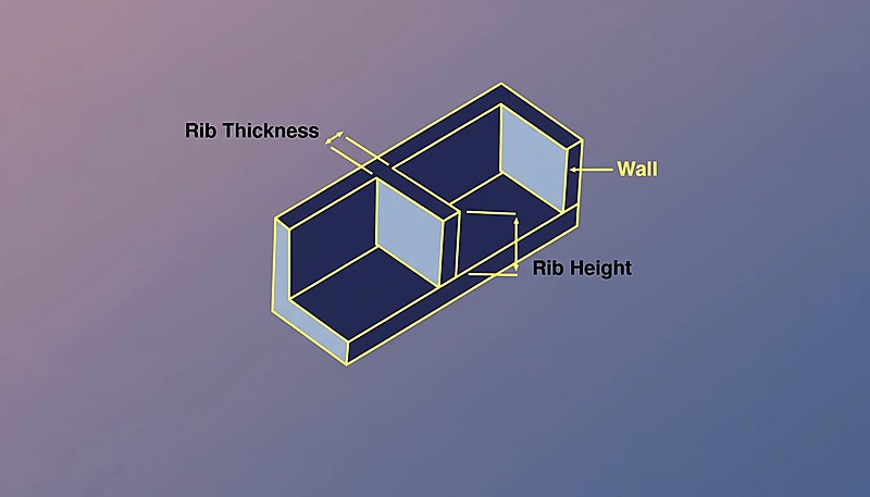
Kaburgalar ve Başlıklar Duvar Kalınlığını Nasıl Etkiler?
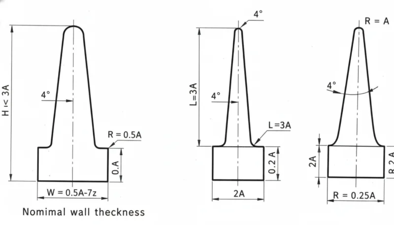
Ribler ve bosslar duvar kalınlığı ile etkileşen en yaygın özelliklerdir. Ribler için: taban kalınlığı nominal duvarın 50–60% olmalı, yükseklik nominal duvarın 3×'ini geçmemeli ve birden fazla ince rib bir uzun, kalın ribden daha iyidir.
Bosslar için çekirdek alma çözümdür — merkez, çekirdek pimi ile oyularak düzgün duvar kalınlığı korunur. Boss dış çapı, delik çapının en fazla 2–3 katı olmalıdır. Bu oranları takip eden parçalar enjeksiyon kalıplama için uygundur enjeksiyon kalıbı[3] kalıp temiz; sapma gösterenler sürekli kalite sorunları oluşturur.
Duvar Kalınlığı Döngü Süresini Nasıl Etkiler?
İçinde enjeksiyon kalıplama, soğutma süresi[4] genellikle en kalın kesitin belirlediği toplam döngü zamanının 50–70%'ini temsil eder.
| Nominal Duvar | Tipik Soğutma Süresi | Göreceli Döngü Maliyeti |
|---|---|---|
| 1.5 mm | 8–12 saniye | 1.0× (baseline) |
| 2.0 mm | 12–18 saniye | 1.3× |
| 2.5 mm | 18–25 saniye | 1.6× |
| 3.0 mm | 25–35 saniye | 2.0× |
| 4.0 mm | 40–60 saniye | 3.0× |
2.0 mm'den 3.0 mm duvarlara geçiş, sadece döngü zamanıyla parça başına üretim maliyetini kabaca iki katına çıkarır. Yapısal olarak mümkün olduğunda, ince duvar tasarımı enjeksiyon kalıplamada en yüksek ROI optimizasyonlarından biridir.
En Yaygın Duvar Kalınlığı Hataları Nelerdir?
- Uniform kalınlığı ihmal etmek. Kalınlık analizi yapılmadan tasarlanan parçalar, nominal duvarın yarısı kadar kesitlerle birlikte nominalden 3× daha kalın alanlar içerir; bu, çökme izleri, çarpılma ve uzun döngü zamanlarına yol açar.
- Kuvvet için fazla kalınlaştırma. Mühendisler, bir kaburganın daha hafif, üretimi daha hızlı ve boyutsal olarak daha kararlı olacağı durumlarda malzeme ekler.
- Rib ölçülerini ihmal etmek. Nominal duvarın –100'ü kadar kaburgalar derin çökme izlerine neden olur. –60 kuralı her malzeme için geçerlidir.
- Ani kalınlık geçişleri. Koniklik olmayan ani değişimler stres yükselticileri ve görsel kusurlar oluşturur.
- Akış simülasyonu yapılmamış. Modern araçlar dolum desenlerini, basıncı ve soğutmayı yüksek doğrulukla tahmin eder. Karmaşık parçalarda simülasyonu atlamak genellikle kayıpla sonuçlanır.
Tasarımınızı Göndermeden Önce Neleri Kontrol Etmelisiniz?
Tasarımınızı kalıplama için göndermeden önce bu kontrol listesini gözden geçirin. Her maddeyi doğrulamak saniyeler alır ve maliyetli kalıp revizyonlarını önleyebilir.
| Check Item | Geçme Kriterleri |
|---|---|
| Nominal duvar malzeme ideal aralığında | ✓ |
| Duvar varyasyonu nominal ±25% içinde | ✓ veya not edildi |
| Tüm kaburgalar ≤60% nominal duvar | ✓ |
| Kalınlık geçişleri 3:1 koniklik kullanır | ✓ |
| Boss OD ≤3× delik çapı | ✓ |
| En kalın kesit belirlendi ve incelendi | ✓ |
| Akış simülasyonu tamamlandı | ✓ |
Kalıp yapılmadan önce duvar kalınlığını optimize etmek esastır — bir kalınlık sorununu düzeltmenin en ucuz yeri CAD'dir, çelikte değil.
Duvar Kalınlığı Hakkında Sıkça Sorulan Sorular
Enjeksiyon Kalıplama için Minimum Duvar Kalınlığı Nedir?
Çoğu mühendislik termoplastikleri için (ABS, PC, Nylon), kısa akış yollarında 0.8 mm pratik minimumdur. PP ve PE gibi yüksek akış malzemelerinde 0.5 mm kadar inceye gidilebilir. Bu minimumlar yüksek enjeksiyon basıncı gerektirir ve eksik dolum riski taşır.
Parça Boyunca Duvar Kalınlığı Değişebilir mi?
Evet, ancak varyasyon nominal duvarın ±25%'si içinde kalmalı ve farklı kalınlıklar arasında 3:1 koniklik oranı kullanılarak kademeli geçişler sağlanmalıdır.
Duvar Kalınlığı Büzülme ile Nasıl İlişkilidir?
Daha kalın bölümler daha fazla büzülür çünkü daha fazla malzeme soğuyarak büzüşmektedir. Bu farklı büzülme, enjeksiyonla kalıplanmış parçalardaki eğilmenin başlıca nedenidir.
Parçanın Kalınlığı Dayanımını Etkiler mi?
Evet, ancak doğrusal olarak değil. Duvar kalınlığını iki katına çıkarmak bükülme sertliğini iki katından fazla artırır (kalınlık küpü ile ölçeklenir). Ancak, duvarları kalınlaştırmak artık stres ve boşluk riskini de artırır. Doğru ölçülendirilmiş ribler genellikle daha iyi kuvvet-ağırlık performansı sağlar.
Duvar Kalınlığı Nasıl Ölçülür?
CAD programınızdaki kalınlık analiz araçlarını kullanın (SolidWorks, Creo ve çoğu MCAD paketinde bunlar içerilir). Fiziksel parçalar üzerinde ultrasonik kalınlık ölçerler tahribatsız ölçüm sağlar, ya kesit keserek kaliperlerle direkt ölçüm yapılır. Üretim sırasında ultrasonik ölçüm, devam eden kalite izleme için standart metottur.
İnce Cidarlı Kalıplama Nedir?
İnce duvar kalıplama, duvar kalınlığı 1.0 mm altında olan parçaları ifade eder (elektronik kasa için bazen 0.3 mm kadar ince). Çok yüksek basınçlar (200+ MPa) kapasitesine sahip yüksek hız makineleri ve özel kalıp tasarımı gerektirir.
Bottom line: Duvar kalınlığını 1.5–3.0 mm arasında tutun, ±25% uniformitesini koruyun, 3:1 taper geçişleri kullanın ve kaburgaları nominal duvarın 50–60%'inde tutun. Bu dört kural duvar kalınlığıyla ilişkili hataların 90%'ini engeller.
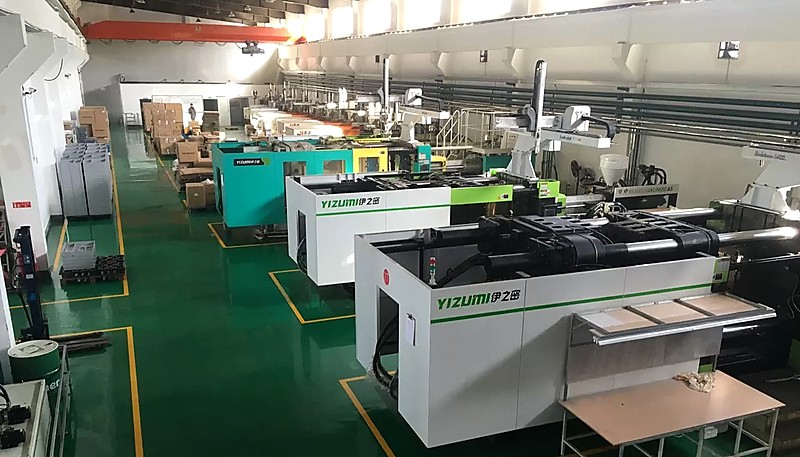
Tasarımın erken döneminde verilen duvar kalınlığı kararları, parçanın kalıplama sürecinde verimli olmasını ya da üretim boyunca sorun çıkarmasını belirler. 400+ malzeme üzerinde binlerce duvar kalınlığı tasarımını optimize eden mühendislerden DFM değerlendirmesi istiyorsanız, ZetarMold ekibimize ulaşın. Shanghai tesisimizde 45 enjeksiyon kalıplama makinesi (90T–1850T) ile çalışıyoruz ve 30+ İngilizce konuşan proje yöneticisi yardıma hazır.
-
Duvar kalınlığı tasarımı — BASF, “Parça ve Kalıp Tasarımı,” Plastik Teknolojisi El Kitabı, 2023. ↩
-
Diferansiyel büzülme — Autodesk, “Moldflow Tasarım Rehberi,” 2024. ↩
-
Tasarım kuralları — “Duvar Kalınlığı En İyi Uygulamaları,” Plastik Mühendisleri Topluluğu, 2025. ↩
-
Soğutma süresi — “Enjeksiyon Kalıplama Soğutma Optimizasyonu,” Plastik Teknolojisi, 2024. ↩


