 Zum Inhalt springen

Wandstärke[1] ist wohl der wichtigste einzelne Designparameter im Spritzgießen. Machen Sie es richtig, und Ihr Teil wird sauber geformt, funktioniert zuverlässig und kostet weniger. Machen Sie es falsch, und Sie haben es mit Einfallstellen, Verzug, Hohlräumen und Zykluszeiten zu tun, die Ihre Marge auffressen.
Key Takeaways:
- Halten Sie die Nennwandstärke für die meisten technischen Thermoplaste zwischen 1,5 und 3,0 mm.
- Halten Sie die Wandstärkenschwankung im gesamten Teil innerhalb von ±25% des Nennwerts.
- Verwenden Sie ein 3:1-Kegelverhältnis für Übergänge zwischen verschiedenen Wandstärken.
- Halten Sie die Rippenbasisdicke bei 50–60% der Nennwand, um Einfallstellen zu vermeiden.
- Die Abkühlzeit skaliert mit dem Quadrat der Wandstärke – Dünnwanddesign hat eine hohe Kapitalrendite.
Dieser Leitfaden behandelt alles, was Ingenieure über Spritzgießen Wandstärke: wie man den richtigen Wert wählt, was passiert, wenn Wände nicht gleichmäßig sind, materialspezifische Richtlinien und die häufigsten Fehler aus Tausenden von DFM-Überprüfungen.
Was ist Wandstärke beim Spritzgießen?
Die Wandstärke ist der Abstand zwischen der äußeren und inneren Oberfläche eines geformten Teils an jedem Querschnitt. Sie bestimmt, wie Kunststoff durch den Spritzgussformhohlraum fließt, wie schnell das Teil abkühlt und ob die endgültigen Abmessungen der Spezifikation entsprechen.
„Die Wandstärkenvariation sollte innerhalb von ±25% des Nennwerts bleiben.“Wahr
Die Branchenrichtlinie ist eine Variation von ±25%. Ein Überschreiten dieses Werts ohne allmähliche Übergänge führt zu unterschiedlichem Schrumpfen, Verzug und Maßinstabilität.
„Eine Rippe mit einer Basisdicke von 80% der Nennwand verursacht keine Einfallstellen.“Falsch
Rippen, die dicker als 50–60% der Nennwand sind, verursachen fast immer sichtbare Einfallstellen, weil die Rippe einen lokalen Hotspot erzeugt, der viel langsamer abkühlt als die umgebende Wand.
Dünnere Wände sparen Material und reduzieren die Zykluszeit, erhöhen aber die Anforderungen an den Einspritzdruck und das Risiko von Kurzschüssen. Dickere Wände fließen leichter, kühlen aber langsam ab, verlängern die Zykluszeit und erhöhen das Risiko von Hohlräumen und Einfallstellen. Der Sweet Spot für die meisten technischen Thermoplaste liegt bei 1,5–3,0 mm. Überprüfen Sie Ihre gewählte Dicke immer anhand des Datenblatts des Materiallieferanten und der Fließsimulationsergebnisse, bevor Sie das Design finalisieren.
Warum ist eine gleichmäßige Wandstärke so wichtig?
Ungleichmäßige Wandstärke ist die Hauptursache für mehr Formfehler als jeder andere einzelne Konstruktionsfehler. Wenn sich die Wände stark unterscheiden, kühlen und schrumpfen dicke Abschnitte mit einer anderen Geschwindigkeit als dünne Abschnitte. Dieses unterschiedliche SchrumpfenSpritzgießen[2] erzeugt innere Spannungen, die sich als Verzug, Einfallstellen und dimensionale Instabilität manifestieren.
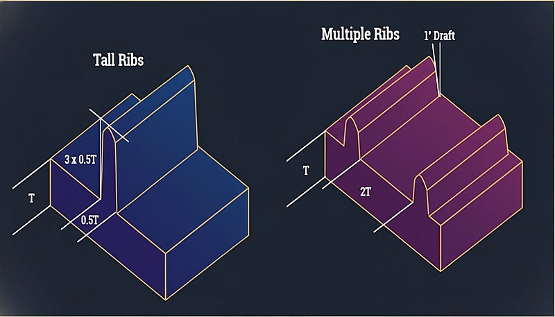
„Mehrere dünne Rippen sind für die Steifigkeit im Allgemeinen besser als eine hohe, dicke Rippe.“Wahr
Mehrere dünne Rippen verteilen die Spannung gleichmäßig, kühlen schneller ab und verursachen minimale Einfallstellen im Vergleich zu einer einzelnen dicken Rippe, die eine lokalisierte thermische Masse erzeugt.
„Ein scharfer 90°-Übergang von 3 mm auf 1,5 mm Wandstärke ist akzeptabel, wenn der dünnere Abschnitt kurz ist.“Falsch
Abrupte Übergänge erzeugen Spannungskonzentrationen unabhängig von der Länge. Sie verursachen Flusszögerung, erhöhte Eigenspannungen und sichtbare Oberflächendefekte. Verwenden Sie immer das 3:1-Kegelverhältnis.
Die Richtlinie ist einfach: Halten Sie die Wandstärke im gesamten Teil innerhalb von ±25% des Nennwerts. Wenn Ihre Nennwandstärke 2,5 mm beträgt, sollte jeder Abschnitt zwischen 1,9 mm und 3,1 mm liegen.

Was ist die empfohlene Wandstärke nach Material?
Verschiedene Materialien haben unterschiedliche Fließeigenschaften und Schwindungsraten. Hier ist eine praktische Referenztabelle basierend auf umfangreichen Produktionsdaten.
| Material | Min Wall (mm) | Idealer Bereich (mm) | Max. praktisch (mm) |
|---|---|---|---|
| ABS | 0.8 | 1.5–3.0 | 4.5 |
| PC (Polycarbonat) | 0.8 | 1.5–3.0 | 4.5 |
| PP (Polypropylen) | 0.6 | 1.2–2.5 | 5.0 |
| PA (Nylon 6/66) | 0.6 | 1.0–3.0 | 4.0 |
| POM (Acetal) | 0.8 | 1.0–3.0 | 4.0 |
| PMMA (Acrylic) | 0.8 | 1,5–3,5 | 5.0 |
| PBT | 0.8 | 1.0–3.0 | 4.0 |
| PE (Polyethylen) | 0.6 | 1.0–2.5 | 5.0 |
| PS (Polystyrol) | 0.8 | 1.0–3.0 | 4.5 |
| TPE/TPU | 0.5 | 1.0–3.0 | 5.0 |
Die minimalen Wandstärken stellen dar, was technisch mit optimierter Verarbeitung möglich ist, nicht was für die Produktion empfohlen wird. Für eine zuverlässige Fertigung sollten Sie im idealen Bereich bleiben.
Wie gestaltet man den Übergang zwischen verschiedenen Wandstärken?
Manchmal sind Wandstärkenschwankungen unvermeidlich. In diesem Fall ist der Übergang zwischen dicken und dünnen Abschnitten kritisch. Die Standardrichtlinie ist ein 3:1-Kegelverhältnis: Für jede 1 mm Änderung der Wandstärke sollte ein gradueller Übergang von mindestens 3 mm Länge vorgesehen werden.
Plötzliche Wandstärkenänderungen verursachen Strömungszögern, Spannungskonzentrationen und sichtbare Einfallstellen auf der gegenüberliegenden Oberfläche. In schweren Fällen brechen Teile an Wandstärkenübergängen während der Montage, weil die Restspannung die Streckgrenze des Materials überschreitet.
Was passiert, wenn Wände zu dick sind?
Dicke Wände verursachen drei Probleme: übermäßige Zykluszeit, innere Hohlräume und Einfallstellen.
Cycle Time Penalty
Die Abkühlzeit skaliert ungefähr mit dem Quadrat der Wandstärke. Ein Teil mit 2 mm Wandstärke kühlt vielleicht in 15 Sekunden ab; die gleiche Geometrie mit 4 mm Wandstärke könnte 50–60 Sekunden benötigen. Bei einer Produktionsserie von 100.000 Teilen sind das Tausende zusätzlicher Maschinenstunden.
„Die Abkühlzeit skaliert mit dem Quadrat der Wandstärke – eine Verdopplung der Wandstärke vervierfacht die Abkühlzeit.“Wahr
Diese nichtlineare Beziehung ist der Grund, warum Dünnwanddesign eine so hohe ROI hat. Eine Reduzierung der Wand von 4 mm auf 2 mm kann die Abkühlzeit um 75 % verkürzen.
„Eine Reduzierung der Wandstärke verbessert immer die Bauteilqualität und die Produktionseffizienz.“Falsch
Während dünne Wände den Materialverbrauch und die Zykluszeit reduzieren, verursachen zu dünne Wände Kurzschüsse, erhöhen die Anforderungen an den Einspritzdruck und beeinträchtigen die strukturelle Integrität. Die optimale Dicke balanciert Fließfähigkeit, Festigkeit und Kosten.
Interne Hohlräume
Wenn dicke Bereiche abkühlen, erstarrt die äußere Haut zuerst, während das Innere noch geschmolzen ist. Wenn sich das Innere zusammenzieht, löst es sich von der erstarrten Haut und erzeugt innere Hohlräume, die die strukturelle Integrität verringern – besonders problematisch bei tragenden Anwendungen.
Sinkende Markierungen
Einfallstellen sind die Oberflächenerscheinung desselben Phänomens. Wenn Material an einer dicken Stelle schrumpft, zieht es die Oberfläche nach innen und erzeugt eine sichtbare Vertiefung, die besonders auf glänzenden Oberflächen auffällt. Das Verhältnis von Rippe zu Wand steuert direkt die Schwere der Einfallstellen: Rippen, die dicker als 50–60 % der Nennwand sind, erzeugen fast immer sichtbare Einfallstellen.
Was passiert, wenn Wände zu dünn sind?
Dünne Wände bergen eigene Risiken. Das unmittelbarste sind Kurzschüsse – die Kunststoffschmelze erstarrt, bevor der Hohlraum vollständig gefüllt ist. Dies ist besonders problematisch bei hochviskosen Materialien wie Polycarbonat und langen Fließwegen, wo die Schmelzeviskosität bereits hoch ist.
Dünne Wände erhöhen auch die Anforderungen an den Einspritzdruck. Wenn der erforderliche Druck die Maschinenkapazität übersteigt, kommt es zu unvollständigen Füllungen und hohen Eigenspannungen.
Die strukturelle Integrität ist ein weiteres Problem – berücksichtigen Sie immer eine Sicherheitsmarge für dünnwandige Teile in Verbraucherprodukten, die Falltests unterzogen werden. Ein Teil, das statische Lasten übersteht, kann bei Aufprall brechen, wenn die Wände zu dünn sind.
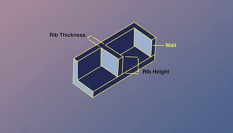
Wie beeinflussen Rippen und Ansätze die Wandstärke?
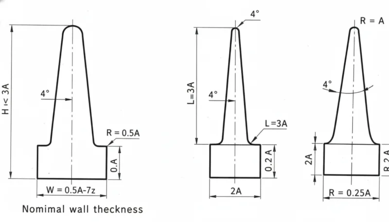
Rippen und Ansätze sind die häufigsten Merkmale, die mit der Wandstärke interagieren. Für Rippen: Die Basisdicke sollte 50–60 % der Nennwandstärke betragen, die Höhe sollte das 3-fache der Nennwandstärke nicht überschreiten, und mehrere dünne Rippen sind besser als eine hohe, dicke Rippe.
Für Stege ist das Aushöhlen die Lösung – das Zentrum mit einem Kernstift aushöhlen, um eine gleichmäßige Wandstärke zu erhalten. Der Außendurchmesser des Stegs sollte nicht mehr als das 2–3-fache des Lochdurchmessers betragen. Teile, die diesen Proportionen folgen, sind spritzgussgerecht. Spritzgussform[3] Werkzeug sauber; Abweichungen verursachen anhaltende Qualitätsprobleme.
Wie beeinflusst die Wandstärke die Zykluszeit?
Unter Spritzgießen, Abkühlzeit[4] stellt typischerweise 50–70 % der gesamten Zykluszeit dar, bestimmt durch den dicksten Querschnitt.
| Nennwandstärke | Typische Abkühlzeit | Relative Zykluskosten |
|---|---|---|
| 1.5 mm | 8–12 Sekunden | 1,0× (Baseline) |
| 2,0 mm | 12–18 Sekunden | 1,3× |
| 2,5 mm | 18–25 Sekunden | 1,6× |
| 3.0 mm | 25–35 Sekunden | 2,0× |
| 4.0 mm | 40–60 Sekunden | 3.0× |
Ein Wechsel von 2,0 mm auf 3,0 mm Wandstärke verdoppelt allein durch die Zykluszeit die Herstellungskosten pro Teil etwa. Dünnwandkonstruktion, wenn strukturell machbar, ist eine der rentabelsten Optimierungen im Spritzguss.
Was sind die häufigsten Fehler bei der Wandstärke?
- Einheitliche Wandstärke vernachlässigen. Teile ohne Dickenanalyse haben Bereiche, die 3-mal dicker als die Nennstärke sind, neben Abschnitten mit halber Nennwandstärke, was zu Einfallstellen, Verzug und längeren Zykluszeiten führt.
- Übermäßige Verdickung für Festigkeit. Ingenieure fügen Material hinzu, wo eine Rippe leichter, schneller zu fertigen und dimensionsstabiler wäre.
- Rippenproportionen ignorieren. Rippen mit 80–100 % der Nennwandstärke verursachen tiefe Einzugsstellen. Die 50–60 %-Regel gilt für jedes Material.
- Plötzliche Dickenübergänge. Scharfe Änderungen ohne Verjüngung erzeugen Spannungskonzentrationen und optische Fehler.
- Keine Strömungssimulation durchführen. Moderne Werkzeuge sagen Füllmuster, Druck und Kühlung mit hoher Genauigkeit voraus. Das Überspringen der Simulation bei komplexen Teilen führt meist zu Verlusten.
Was sollten Sie vor dem Einreichen Ihres Designs überprüfen?
Bevor Sie Ihr Design für die Werkzeugherstellung einreichen, gehen Sie diese Checkliste durch. Jeder Punkt dauert Sekunden zu prüfen und kann kostspielige Werkzeugänderungen verhindern.
| Check Item | Kriterien für Bestehen |
|---|---|
| Nennwandstärke innerhalb des idealen Materialbereichs | ✓ |
| Wandvariation innerhalb von ±25 % der Nennstärke | ✓ oder vermerkt |
| Alle Rippen ≤60 % der Nennwandstärke | ✓ |
| Dickenübergänge verwenden 3:1-Verjüngung | ✓ |
| Steg-Außendurchmesser ≤3× Lochdurchmesser | ✓ |
| Dickster Bereich identifiziert und überprüft | ✓ |
| Strömungssimulation abgeschlossen | ✓ |
Die Optimierung der Wandstärke vor dem Bau des Werkzeugs ist entscheidend – der günstigste Ort, um ein Dickenproblem zu beheben, ist im CAD, nicht im Stahl.
Häufig gestellte Fragen zur Wandstärke
Was ist die minimale Wandstärke für das Spritzgießen?
Für die meisten technischen Thermoplaste (ABS, PC, Nylon) ist 0,8 mm das praktische Minimum für kurze Fließwege. Für hochfließfähige Materialien wie PP und PE kann man bis zu 0,5 mm dünn gehen. Diese Mindestwerte erfordern hohen Einspritzdruck und bergen das Risiko von unvollständigen Formteilen.
Kann die Wandstärke innerhalb eines Bauteils variieren?
Ja, aber die Variation sollte innerhalb ±25% der nominalen Wand bleiben, mit graduellen Übergängen unter Verwendung eines 3:1 Verjüngungsverhältnisses zwischen verschiedenen Dicke.
Wie hängt die Wandstärke mit dem Schrumpfen zusammen?
Dicker Abschnitte schrumpfen stärker, weil mehr Material abkühlt und sich zusammenzieht. Diese unterschiedliche Schrumpfung ist die Hauptursache für Verzug bei spritzgegossenen Teilen.
Beeinflusst die Wandstärke die Bauteilfestigkeit?
Ja, aber nicht linear. Eine Verdopplung der Wandstärke verdoppelt die Biegesteifigkeit mehr als nur das Doppelte (sie skaliert mit der dritten Potenz der Dicke). Allerdings erhöht eine Verdickung der Wände auch die Eigenspannungen und das Risiko von Lufteinschlüssen. Richtig proportionierte Rippen erreichen oft eine bessere Festigkeits-Gewichts-Leistung.
Wie misst man die Wandstärke?
Verwenden Sie Wandstärkenanalyse-Tools in Ihrer CAD-Software (SolidWorks, Creo und die meisten MCAD-Pakete haben diese integriert). Bei physischen Teilen bieten Ultraschall-Dickenmessgeräte zerstörungsfreie Messungen, oder schneiden Sie Querschnitte für direkte Messungen mit Messschiebern. Während der Produktion ist die Ultraschallmessung die Standardmethode für die laufende Qualitätsüberwachung.
Was ist Thin-Wall-Molding?
Dünnwandiges Spritzgießen bezieht sich auf Teile mit Wandstärken unter 1,0 mm (manchmal bis zu 0,3 mm für Elektronikgehäuse). Es erfordert Hochgeschwindigkeitsmaschinen mit sehr hohen Drücken (200+ MPa) und spezialisierte Werkzeugkonstruktion.
Bottom line: Halten Sie die Wandstärke zwischen 1,5–3,0 mm, gewährleisten Sie eine Gleichmäßigkeit von ±25%, verwenden Sie 3:1-Kegelübergänge und halten Sie Rippen bei 50–60% der Nennwandstärke. Diese vier Regeln verhindern 90% der wandstärkebedingten Fehler.
Entscheidungen zur Wandstärke, die früh im Design getroffen werden, bestimmen, ob Ihr Teil effizient geformt wird oder während der gesamten Produktion Probleme bereitet. Wenn Sie eine DFM-Prüfung von Ingenieuren wünschen, die Tausende von Wandstärkendesigns über 400+ Materialien hinweg optimiert haben, wenden Sie sich an unser Team bei ZetarMold. Wir betreiben 45 Spritzgießmaschinen (90T–1850T) von unserer Einrichtung in Shanghai aus, mit über 30 englischsprachigen Projektmanagern, die bereit sind zu helfen.
-
Ausführung der Wandstärke — BASF, „Teil- und Werkzeugkonstruktion“, Plastics Technology Handbook, 2023. ↩
-
Differenzielles Schrumpfen — Autodesk, „Moldflow Design Guide“, 2024. ↩
-
Designrichtlinien — „Best Practices für Wandstärken“, Society of Plastics Engineers, 2025. ↩
-
Abkühlungszeit — „Optimierung der Spritzgießkühlung“, Plastics Technology, 2024. ↩


