 Przejdź do treści

Grubość ścianki[1] jest prawdopodobnie najważniejszym parametrem projektowym w wtrysku. Dobrze dobrana zapewnia czysty formowanie, niezawodną funkcjonalność i niższe koszty. Źle dobrana prowadzi do śladów zapadania, odkształceń, pustek i czasów cyklu, które niszczą marżę.
Kluczowe wnioski:
- Utrzymuj nominalną grubość ścianki między 1,5 a 3,0 mm dla większości termoplastycznych tworzyw inżynieryjnych.
- Utrzymuj zmienność grubości ścianki w granicach ±25% wartości nominalnej w całej części.
- Użyj współczynnika stożkowania 3:1 dla przejść między różnymi grubościami ścianek.
- Utrzymuj grubość podstawy żebra na poziomie 50–60% nominalnej grubości ścianki, aby uniknąć wciągnięć.
- Czas chłodzenia skaluje się z kwadratem grubości ścianki — projekt cienkościenny ma wysoką stopę zwrotu z inwestycji.
Ten przewodnik obejmuje wszystko, co inżynierowie muszą wiedzieć o formowanie wtryskowe grubość ścianki: jak wybrać właściwą wartość, co się dzieje gdy ścianki nie są jednolite, wytyczne materiałowe, oraz najczęstsze błędy z tysięcy przeglądów DFM.
Co to jest grubość ścianki w formowaniu wtryskowym?
Grubość ścianki jest odległością między zewnętrzną i wewnętrzną powierzchnią części formowanej w dowolnym przekroju. Określa, jak plastik przepływa przez wnękę formy wtryskowej, jak szybko część się chłodzi i czy końcowe wymiary spełniają specyfikację.
„Zmienność grubości ścianki powinna pozostawać w zakresie ±25% wartości nominalnej.”Prawda
Wytyczna branżowa to zmienność ±25%. Przekroczenie tego bez stopniowych przejść powoduje różnicowy skurcz, odkształcenia i niestabilność wymiarową.
„Żebro o grubości podstawy równiej 80% nominalnej ścianki nie powoduje śladów zapadania.”Fałsz
Żebra grubsze niż 50–60% nominalnej grubości ścianki prawie zawsze powodują widoczne wciągnięcia, ponieważ żebro tworzy zlokalizowany punkt gorący, który stygnie znacznie wolniej niż otaczająca ścianka.
Cieńsze ścianki oszczędzają materiał i skracają czas cyklu, ale zwiększają wymagania dotyczące ciśnienia wtrysku i ryzyko niedopływu. Grubsze ścianki płyną łatwiej, ale stygną wolno, wydłużając czas cyklu i zwiększając ryzyko pustych przestrzeni i wciągnięć. Optymalna wartość dla większości termoplastycznych tworzyw inżynieryjnych to 1,5–3,0 mm. Zawsze sprawdzaj wybraną grubość względem karty danych dostawcy materiału i wyników symulacji przepływu przed ostatecznym zatwierdzeniem projektu.
Dlaczego jednolita grubość ścianki jest tak ważna?
Niejednolita grubość ścianki jest główną przyczyną więcej błędów formowania niż każdy inny błąd projektowy. Gdy ścianki różnią się znacznie, grube sekcje chłodzą się i kurczą w innym tempie niż cienkie. Ta różnicowa kurczliwośćformowanie wtryskowe[2] tworzy naprężenia wewnętrzne, które manifestują się jako odkształcenia, ślady zapadania i niestabilność wymiarowa.
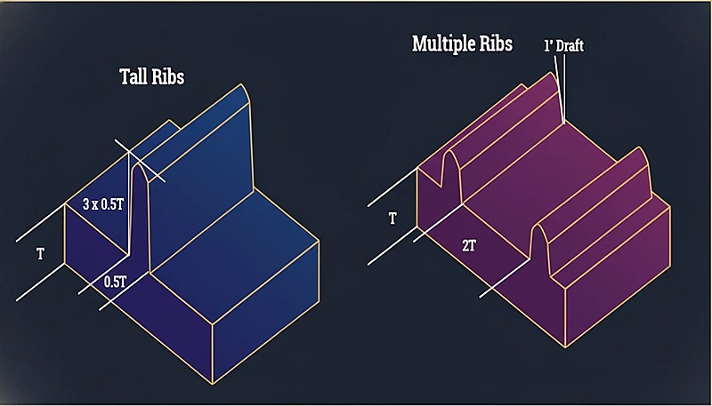
„Wiele cienkich żeber jest zazwyczaj lepszych niż jedno wysokie, grube żebro pod względem sztywności.”Prawda
Wiele cienkich żeber równomiernie rozkłada naprężenia, chłodzi się szybciej i powoduje minimalne ślady zapadania w porównaniu do jednego grubego żebra tworzącego lokalną masę termiczną.
„Ostre przejście pod kątem 90° od ścianki 3 mm do 1,5 mm jest dopuszczalne, jeśli cieńszy odcinek jest krótki.”Fałsz
Nagłe przejścia tworzą koncentrację naprężeń niezależnie od długości. Powodują zahamowanie przepływu, zwiększone naprężenia szczątkowe i widoczne defekty powierzchni. Zawsze stosuj współczynnik stożkowania 3:1.
Wytyczna jest prosta: utrzymuj grubość ścianki w granicach ±25% wartości nominalnej w całej części. Jeśli twoja nominalna ścianka ma 2,5 mm, każdy odcinek powinien mieścić się między 1,9 mm a 3,1 mm.
Jaka jest zalecana grubość ścianki w zależności od materiału?
Różne materiały mają różne właściwości przepływu i współczynniki skurczu. Oto praktyczna tabela referencyjna oparta na obszernych danych produkcyjnych.
| Materiał | Min Wall (mm) | Zalecany zakres (mm) | Maksymalna praktyczna (mm) |
|---|---|---|---|
| ABS | 0.8 | 1.5–3.0 | 4.5 |
| PC (poliwęglan) | 0.8 | 1.5–3.0 | 4.5 |
| PP (polipropylen) | 0.6 | 1,2–2,5 | 5.0 |
| PA (Nylon 6/66) | 0.6 | 1.0–3.0 | 4.0 |
| POM (Acetal) | 0.8 | 1.0–3.0 | 4.0 |
| PMMA (Acrylic) | 0.8 | 1.5–3.5 | 5.0 |
| PBT | 0.8 | 1.0–3.0 | 4.0 |
| PE (polietylen) | 0.6 | 1.0–2.5 | 5.0 |
| PS (polistyren) | 0.8 | 1.0–3.0 | 4.5 |
| TPE/TPU | 0.5 | 1.0–3.0 | 5.0 |
Minimalne wartości grubości ścianki reprezentują możliwości techniczne przy optymalizacji procesu, nie zalecane dla produkcji. Dla niezawodnej produkcji należy pozostawać w zalecanym zakresie.
Jak przechodzić między różnymi grubościami ścianek?
Czasami zmienność grubości ścianki jest nieunikniona. Kiedy to się zdarzy, przejście między grubymi i cienkimi sekcjami jest kluczowe. Standardowa wytyczna to współczynnik stożkowania 3:1: na każdą zmianę grubości o 1 mm zapewnij co najmniej 3 mm stopniowego przejścia.
Nagłe zmiany grubości powodują zahamowanie przepływu, koncentrację naprężeń i widoczne ślady zapadania na przeciwnej powierzchni. W ekstremalnych przypadkach części pękają na przejściach grubości podczas montażu, gdy naprężenia szczątkowe przekraczają granicę plastyczności materiału.
Co się dzieje gdy ścianki są zbyt grube?
Grube ścianki powodują trzy problemy: nadmierny czas cyklu, puste przestrzenie wewnętrzne i wciągnięcia.
Cycle Time Penalty
Czas chłodzenia jest proporcjonalny do kwadratu grubości ścianki. Część o ściankach 2 mm może schłodzić się w 15 sekund; ta sama geometria o ściankach 4 mm może wymagać 50–60 sekund. W produkcji 100 000 części to tysiące dodatkowych godzin pracy maszyny.
„Czas chłodzenia jest proporcjonalny do kwadratu grubości ścianki — podwojenie grubości czterokrotnie zwiększa czas chłodzenia.”Prawda
Ta nieliniowa relacja tłumaczy wysoką ROI projektowania cienkich ścianek. Zmniejszenie grubości z 4mm do 2mm może skrócić czas chłodzenia o 75%.
„Zmniejszenie grubości ścianki zawsze poprawia jakość części i wydajność produkcji.”Fałsz
Choć cienkie ścianki zmniejszają użycie materiału i czas cyklu, ścianki zbyt cienkie powodują niedostatek, zwiększają wymagania dotyczące ciśnienia wtrysku i osłabiają integralność strukturalną. Optymalna grubość balansuje przepływ, siłę i koszt.
Pustki wewnętrzne
Gdy grube przekroje stygną, zewnętrzna warstwa krzepnie pierwsza, podczas gdy wnętrze pozostaje stopione. Gdy wnętrze kurczy się, odrywa się od zestalonej skorupy, tworząc wewnętrzne pustki, które zmniejszają integralność strukturalną — szczególnie problematyczne w zastosowaniach nośnych.
Znaki zlewu
Wklęśnięcia są powierzchniową manifestacją tego samego zjawiska. Gdy materiał w grubym przekroju kurczy się, pociąga powierzchnię do wewnątrz, tworząc widoczne zagłębienie, szczególnie zauważalne na błyszczących powierzchniach. Stosunek żeber do ściany bezpośrednio kontroluje nasilenie wklęśnięć: żebra grubsze niż 50–60% nominalnej ściany prawie zawsze powodują widoczne wklęśnięcia.
Co się dzieje, gdy ścianki są zbyt cienkie?
Cienkie ściany niosą ze sobą własne ryzyko. Najbardziej bezpośrednim jest niedolanie — stop tworzywa zamarza przed całkowitym wypełnieniem wnęki. Jest to szczególnie problematyczne w przypadku materiałów o wysokiej lepkości, takich jak poliwęglan, oraz długich ścieżek przepływu, gdzie lepkość stopu jest już wysoka.
Cienkie ściany zwiększają również wymagania dotyczące ciśnienia wtrysku. Jeśli wymagane ciśnienie przekracza możliwości maszyny, dochodzi do niepełnego wypełnienia i wysokich naprężeń szczątkowych.
Integralność strukturalna jest kolejnym zagrożeniem — zawsze należy uwzględnić margines bezpieczeństwa dla części z cienkich ścian w produktach konsumenckich poddanych testowi upadku. Część, która wytrzymuje statyczne obciążenia, może się rozłamać przy uderzeniu, jeśli ścianki są zbyt cienkie.
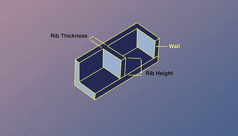
Jak żebra i wypustki wpływają na grubość ścianki?
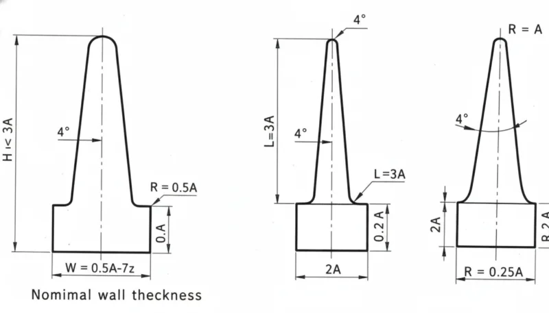
Żebra i wypustki to najczęstsze elementy oddziałujące z grubością ścianki. Dla żeber: grubość podstawy powinna wynosić 50–60% grubości nominalnej ścianki, wysokość nie powinna przekraczać 3× nominalnej ścianki, a wiele cienkich żeber jest lepsze niż jedno wysokie, grube żebro.
Dla wypustek, rdzeniowanie jest rozwiązaniem — wydrąż środek za pomocą trzpienia rdzeniowego, aby zachować jednolitą grubość ścianki. Zewnętrzna średnica wypustki nie powinna przekraczać 2–3 razy średnicy otworu. Części, które zachowują te proporcje wtryskiwania. forma wtryskowa[3] formować czysto; te, które odbiegają, generują ciągłe problemy z jakością.
Jak grubość ścianki wpływa na czas cyklu?
W formowanie wtryskowe, czas chłodzenia[4] typowo stanowi 50–70% całkowitego czasu cyklu, regulowany przez najgrubszy przekrój.
| Nominalna ściana | Typowy czas chłodzenia | Względny koszt cyklu |
|---|---|---|
| 1.5 mm | 8–12 sekund | 1.0× (baseline) |
| 2,0 mm | 12–18 seconds | 1.3× |
| 2,5 mm | 18–25 sekund | 1,6× |
| 3.0 mm | 25–35 sekund | 2,0× |
| 4,0 mm | 40–60 sekund | 3.0× |
Przejście z ścianek 2,0 mm na 3,0 mm podwaja koszt produkcji jednej części tylko poprzez czas cyklu. Projektowanie cienkich ścian, gdy jest strukturalnie możliwe, jest jedną z optymalizacji o najwyższym ROI w wtrysku.
Jakie są najczęstsze błędy dotyczące grubości ścianek?
- Zaniedbanie jednolitej grubości. Części zaprojektowane bez analizy grubości mają obszary 3× grubsze od nominalnych obok sekcji o połowie nominalnej ścianki, powodując wgłębienia, odkształcenia i wydłużone czasy cyklu.
- Przedawkowanie materiału dla zwiększenia wytrzymałości. Inżynierowie dodają materiał, gdy żebro byłoby lżejsze, szybciej produkowane i bardziej stabilne wymiarowo.
- Ignorowanie proporcji żeber. Żebra o grubości 80–100% ścianki nominalnej powodują głębokie wciągnięcia. Zasada 50–60% dotyczy każdego materiału.
- Nagłe przejścia grubości. Nagłe zmiany bez przejścia tworzą miejsca koncentracji naprężeń i defekty kosmetyczne.
- Nie uruchomiono symulacji przepływu. Nowoczesne narzędzia przewidują wzory wypełnienia, ciśnienie i chłodzenie z wysoką dokładnością. Pominięcie symulacji na złożonych części zazwyczaj prowadzi do strat.
Co należy sprawdzić przed wysłaniem projektu?
Przed przesłaniem projektu do wykonania narzędzi, przejdź przez tę listę kontrolną. Każdy punkt zajmuje sekundy do sprawdzenia i może zapobiec kosztownym modyfikacjom narzędzi.
| Check Item | Kryteria zaliczenia |
|---|---|
| Ścianka nominalna w idealnym zakresie materiału | ✓ |
| Zmiana ściany w zakresie ±25% nominalnej | ✓ lub zaznaczone |
| Wszystkie żebra ≤60% nominalnej ścianki | ✓ |
| Przejścia grubości stosują stożek 3:1 | ✓ |
| Zewn. średnica wypustki ≤3× średnica otworu | ✓ |
| Najgrubszy przekrój zidentyfikowany i sprawdzony | ✓ |
| Symulacja przepływu zakończona | ✓ |
Optymalizacja grubości ścianki przed zbudowaniem formy jest kluczowa — najtańszym miejscem do naprawienia problemu z grubością jest CAD, a nie stal.
Najczęściej zadawane pytania dotyczące grubości ścianki
Jakie jest minimalne grubość ścianki dla wtrysku?
Dla większości termoplastów konstrukcyjnych (ABS, PC, nylon), 0,8 mm jest praktycznym minimum dla krótkich ścieżek przepływu. Dla materiałów wysokoprzepływowych jak PP i PE, można osiągnąć nawet 0,5 mm. Te minima wymagają wysokiego ciśnienia wtrysku i niosą ryzyko niedostatecznego wypełnienia.
Czy Grubość Ściany Może Się Różnić w Obrębie Części?
Tak, ale zmienność powinna mieścić się w granicach ±25% nominalnej ściany, z płynnymi przejściami przy użyciu współczynnika stożkowości 3:1 między różnymi grubościami.
Jak Grubość Ściany Jest Powiązana ze Skurczem?
Grubsze sekcje kurczą się bardziej, ponieważ więcej materiału stygnie i kurczy się. To zróżnicowane kurczenie jest główną przyczyną odkształceń w wtryskiwanych częściach.
Czy grubość ścianki wpływa na wytrzymałość części?
Tak, ale nie liniowo. Podwojenie grubości ścianki zwiększa sztywność na zginanie ponad dwukrotnie (skaluje się z grubością do potęgi trzeciej). Jednak zwiększanie grubości ścianek podnosi również naprężenia resztkowe i ryzyko pustek. Właściwie proporcjonowane żebra często zapewniają lepsze osiągi wytrzymałości do wagi.
Jak mierzyć grubość ścianki?
Użyj narzędzi analizy grubości w oprogramowaniu CAD (SolidWorks, Creo i większość pakietów MCAD ma je wbudowane). W przypadku fizycznych części, ultradźwiękowe mierniki grubości zapewniają nieniszczący pomiar lub wykonaj przekroje do bezpośredniego pomiaru suwmiarką. Podczas produkcji, pomiar ultradźwiękowy jest standardową metodą ciągłego monitorowania jakości.
Co to jest formowanie cienkościenne?
Formowanie cienkościenne odnosi się do części o grubości ścianki poniżej 1,0 mm (czasem nawet 0,3 mm dla obudów elektroniki). Wymaga maszyn wysokociśnieniowych (200+ MPa) i specjalistycznego projektu formy.
Bottom line: Utrzymuj grubość ścianki między 1,5–3,0 mm, zachowaj jednorodność ±25%, stosuj przejścia stożkowe 3:1 i utrzymuj żebra na poziomie 50–60% grubości ścianki nominalnej. Te cztery zasady zapobiegają 90% wad związanych z grubością ścianki.
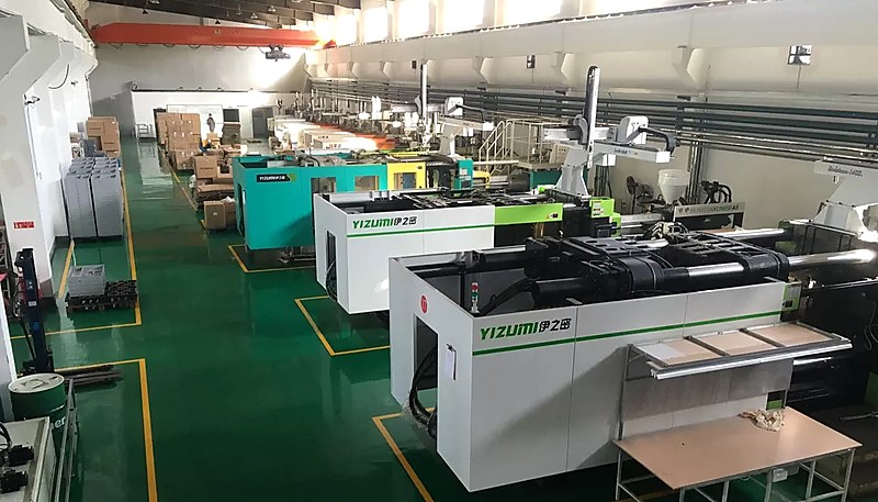
Decyzje dotyczące grubości ścianki podjęte na wczesnym etapie projektowania decydują o tym, czy część będzie formowana efektywnie, czy będzie sprawiać problemy przez całą produkcję. Jeśli chcesz przeglądu DFM od inżynierów, którzy zoptymalizowali tysiące projektów grubości ścianki dla ponad 400 materiałów, skontaktuj się z naszym zespołem w ZetarMold. Obsługujemy 45 maszyn do formowania wtryskowego (90T–1850T) z naszego zakładu w Szanghaju, z ponad 30 anglojęzycznymi kierownikami projektów gotowymi do pomocy.
-
Grubość ścianki — BASF, „Projektowanie części i formy”, Podręcznik technologii tworzyw sztucznych, 2023. ↩
-
Różnicowa kurczliwość — Autodesk, „Moldflow Design Guide”, 2024. ↩
-
Wytyczne projektowe — „Najlepsze praktyki dotyczące grubości ścianki”, Society of Plastics Engineers, 2025. ↩
-
Czas chłodzenia — „Optymalizacja chłodzenia w formowaniu wtryskowym”, Plastics Technology, 2024. ↩


