 コンテンツへスキップ

肉厚[1] 肉厚は、射出成形においておそらく最も重要な設計パラメータです。適切に設計すれば、部品はきれいに成形され、確実に機能し、コストも削減できます。誤った設計では、シンクマーク、反り、ボイド、マージンを圧迫するサイクルタイムといった問題に直面します。
Key Takeaways:
- ほとんどのエンジニアリング熱可塑性プラスチックでは、公称肉厚を1.5~3.0 mmの間に保つこと。
- 部品全体で基準値からの肉厚変動を±25%以内に維持します。
- 異なる壁厚間の遷移には3:1のテーパー比を使用してください。
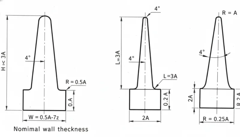
- シンクマークを避けるため、リブ基部の肉厚は基準肉厚の50〜60%に保ちます。
- 冷却時間は肉厚の二乗に比例します — 薄肉設計は投資対効果が高いです。
このガイドでは、エンジニアが知っておくべきすべての内容を網羅しています: 射出成形 壁厚:適切な値の選び方、壁厚が不均一な場合の影響、材料別のガイドライン、数千件のDFMレビューから得られた最も一般的なミスについて。
射出成形における肉厚とは?
肉厚は、成形部品の任意の断面における外表面と内表面の距離です。プラスチックが射出成形金型キャビティを流れる様子、部品の冷却速度、最終寸法が仕様を満たすかどうかを決定します。
「肉厚の変動は、公称値の±25%以内に収めるべきである。」真
業界ガイドラインは±25%の変動です。これを超える急激な変化は、収縮率の差、反り、寸法不安定を引き起こします。
「ベース厚が公称壁厚の80%に等しいリブは、シンクマークを生じません。」偽
リブが基準肉厚の50〜60%より厚い場合、ほぼ常に見えるシンクマークが発生します。これはリブが局所的な高温部を作り、周囲の肉厚よりもはるかに遅く冷却されるためです。
薄肉化は材料を節約しサイクルタイムを短縮しますが、射出圧力要件を増加させショートショットのリスクを高めます。厚肉部は流動性が良くなりますが冷却が遅く、サイクルタイムを延長しボイドやシンクマークのリスクを増加させます。ほとんどのエンジニアリング熱可塑性樹脂の最適点は1.5〜3.0 mmです。設計を確定する前に、選択した肉厚を材料サプライヤーのデータシートと流動シミュレーション結果で必ず確認してください。
なぜ均一な肉厚が重要なのですか?
不均一な肉厚は、他の単一の設計誤差よりも多くの成形不良の根本原因です。肉厚が大きく異なると、厚肉部と薄肉部では冷却速度と収縮率が異なります。この収縮率の差が射出成形[2] 内部応力を生み出し、反り、シンクマーク、寸法不安定として現れます。
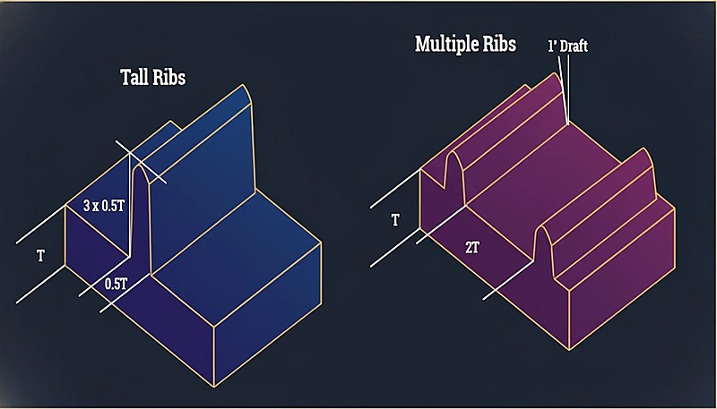
「剛性を得るには、1本の高く厚いリブよりも複数の薄いリブの方が一般的に優れています。」真
複数の薄いリブは応力を均等に分散し、冷却が速く、局所的な熱容量を作る単一の厚いリブと比べて最小限のシンクマークしか生じません。
「薄肉部が短い場合、3 mmから1.5 mmへの壁厚の鋭い90°変化は許容されます。」偽
急激な遷移は、長さに関わらず応力集中を生み出します。流動の遅れ、残留応力の増加、目に見える表面欠陥の原因となります。常に3:1のテーパー比を使用してください。
ガイドラインは明確です:部品全体を通じて肉厚を基準値の±25%以内に維持します。基準肉厚が2.5 mmの場合、すべての部分は1.9 mmから3.1 mmの間であるべきです。
材料別の推奨肉厚は?
材料によって流動特性や収縮率が異なります。以下は、豊富な生産データに基づく実用的な参考表です。
| 素材 | Min Wall (mm) | 理想的な範囲(mm) | 実用的最大値(mm) |
|---|---|---|---|
| ABS | 0.8 | 1.5–3.0 | 4.5 |
| PC(ポリカーボネート) | 0.8 | 1.5–3.0 | 4.5 |
| PP(ポリプロピレン) | 0.6 | 1.2–2.5 | 5.0 |
| PA(ナイロン6/66) | 0.6 | 1.0–3.0 | 4.0 |
| POM (Acetal) | 0.8 | 1.0–3.0 | 4.0 |
| PMMA (Acrylic) | 0.8 | 1.5~3.5 | 5.0 |
| PBT | 0.8 | 1.0–3.0 | 4.0 |
| PE(ポリエチレン) | 0.6 | 1.0–2.5 | 5.0 |
| PS(ポリスチレン) | 0.8 | 1.0–3.0 | 4.5 |
| TPE/TPU | 0.5 | 1.0–3.0 | 5.0 |
最小肉厚値は、最適化された加工条件下で技術的に可能な値を示しており、生産に推奨される値ではありません。確実な製造のためには、理想的な範囲内に留めてください。
異なる肉厚間をどのように遷移させますか?
肉厚の変動が避けられない場合もあります。その場合、厚肉部と薄肉部の間の遷移が重要です。標準的なガイドラインは3:1のテーパー比です:肉厚が1 mm変化するごとに、少なくとも3 mmの段階的な遷移を設けます。
急激な肉厚変化は、流動のためらい、応力集中、および反対面に見えるシンクマークを引き起こします。深刻な場合、組立時に肉厚変化部で部品が破損することがあります。残留応力が材料の降伏強度を超えるためです。
肉厚が厚すぎるとどうなるか?
厚肉は、過剰なサイクルタイム、内部ボイド、シンクマークという3つの問題を引き起こします。
サイクルタイムの悪化
冷却時間は壁厚の約2乗に比例して増加します。壁厚2 mmの部品は15秒で冷却されるかもしれませんが、同じ形状で壁厚4 mmの場合、50〜60秒かかる可能性があります。10万個の生産ロットでは、これが数千時間の追加機械稼働時間となります。
「冷却時間は肉厚の二乗に比例します — 肉厚を2倍にすると冷却時間は4倍になります。」真
この非線形関係こそが、薄肉設計が高い投資対効果を持つ理由です。肉厚を4mmから2mmに減らすと、冷却時間を75%削減できる可能性があります。
「肉厚を減らすことは常に部品品質と生産効率を向上させます。」偽
薄肉化は材料使用量とサイクルタイムを削減しますが、肉厚が薄すぎるとショートショットを引き起こし、射出圧力要件を増加させ、構造的完全性を損ないます。最適な肉厚は流動性、強度、コストのバランスを取ります。
内部ボイド
肉厚部が冷却する際、外側の表皮が先に固化し、内部はまだ溶融状態です。内部が収縮すると、固化した表皮から引き離され、内部空隙が生じ、構造強度が低下します。これは特に負荷のかかる用途で問題となります。
シンクマーク
シンクマークは同じ現象が表面に現れたものです。肉厚部分の材料が収縮すると、表面を内側に引き込み、特に光沢面で目立つ窪みを生じます。リブと肉厚の比率はシンクの深刻さを直接左右します:公称肉厚の50~60%より厚いリブは、ほぼ常に目に見えるシンクマークを生み出します。
肉厚が薄すぎるとどうなるか?
薄肉化には独自のリスクがあります。最も直接的なのはショートショットです。これはプラスチック溶融体がキャビティを完全に充填する前に固化してしまう現象です。ポリカーボネートのような高粘度材料や長い流動経路では特に問題となります。
薄肉壁は射出圧力の要求も高めます。必要な圧力が機械の能力を超えると、充填不足や高い残留応力が生じます。
構造的完全性も懸念事項です — 落下試験が行われる民生品の薄肉部品には、常に安全マージンを含めてください。静的荷重には耐える部品でも、肉厚が薄すぎると衝撃で破損する可能性があります。
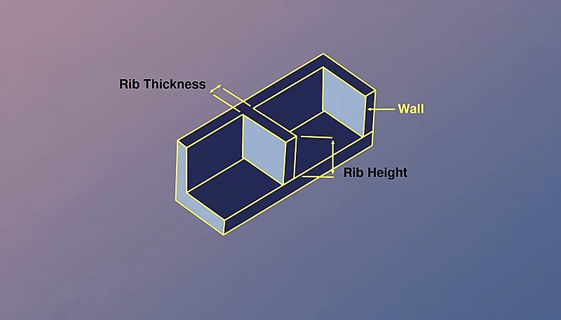
リブとボスは肉厚にどのように影響しますか?
リブとボスは肉厚と関係する最も一般的な形状です。リブの場合:基部の厚さは基本肉厚の50~60%、高さは基本肉厚の3倍を超えず、複数の細いリブが1本の高く厚いリブよりも優れています。
ボスの場合、コア抜きが解決策です — コアピンで中心をくり抜き、均一な肉厚を維持します。ボスの外径は穴径の2~3倍以内に収めるべきです。これらの比例関係を守った部品は射出成形に適しています。 射出成形金型[3] きれいに成形されます;それから外れると、継続的な品質問題を生み出します。
肉厚はサイクル時間にどのように影響しますか?
で 射出成形, 冷却時間[4] 通常は総サイクル時間の50~70%を占め、最も厚い断面によって決定されます。
| 基本肉厚 | 典型的な冷却時間 | 相対サイクルコスト |
|---|---|---|
| 1.5 mm | 8–12 秒 | 1.0× (baseline) |
| 2.0 mm | 12–18 秒 | 1.3× |
| 2.5 mm | 18~25秒 | 1.6× |
| 3.0 mm | 25–35 秒 | 2.0× |
| 4.0 mm | 40–60 秒 | 3.0× |
肉厚を2.0 mmから3.0 mmにすると、サイクルタイムだけでも部品あたりの製造コストが約2倍になります。構造的に可能な場合の薄肉設計は、射出成形における最も投資対効果の高い最適化の一つです。
最も一般的な肉厚の間違いは何ですか?
- 均一肉厚を無視。 肉厚解析なしで設計された部品は、公称肉厚の半分の箇所と、公称肉厚の3倍の箇所が混在し、シンクマーク、反り、サイクルタイムの延長を引き起こします。
- 強度のための過剰な肉厚増加。 リブの方が軽量で生産が速く、寸法安定性に優れる場合、エンジニアは材料を追加する。
- リブのプロポーションを無視。 基本肉厚の80~100%のリブは深いシンクマークを引き起こします。50~60%のルールは全ての材料に適用されます。
- 急激な肉厚変化。 テーパーのない急激な肉厚変化は、応力集中部と外観不良を生み出します。
- フローシミュレーションを実行しない。 最新のツールは充填パターン、圧力、冷却を高精度で予測します。複雑な部品でシミュレーションを省略すると、通常は損失が生じます。
デザイン提出前に確認すべき事項は何ですか?
設計を金型製作に提出する前に、このチェックリストを確認してください。各項目の確認には数秒しかかからず、高額な金型修正を防ぐことができます。
| Check Item | 合格基準 |
|---|---|
| 材料の理想範囲内の公称肉厚 | ✓ |
| 肉厚変動は公称値の ±25% 以内 | ✓ または注記 |
| すべてのリブは基本肉厚の60%以下 | ✓ |
| 肉厚遷移は 3:1 のテーパーを使用 | ✓ |
| ボス外径 ≤3× 穴径 | ✓ |
| 最厚部を特定し確認済み | ✓ |
| 流動シミュレーション完了 | ✓ |
金型が製作される前に肉厚を最適化することが不可欠です — 肉厚の問題を修正する最も安価な場所は、CAD上であって、鋼材の中ではありません。
肉厚に関するよくある質問
射出成形における最小肉厚は何ですか?
ほとんどのエンジニアリング熱可塑性樹脂(ABS、PC、ナイロン)では、短い流動経路の場合、実用的な最小肉厚は 0.8 mm です。PP や PE などの高流動材料では、0.5 mm まで薄くできます。これらの最小値は高い射出圧力を必要とし、ショートショットのリスクを伴います。
部品全体で肉厚は変化しますか?
はい、ただし変動は公称壁厚の±25%以内に収め、異なる厚さ間の遷移は3:1のテーパー比を用いて段階的に行う必要があります。
壁厚は収縮とどのように関連していますか?
厚い部分はより多くの材料が冷却収縮するため、より大きく収縮します。この不均一な収縮が射出成形部品の反りの主な原因となります。
壁厚は部品の強度に影響しますか?
はい、しかし線形ではありません。肉厚を2倍にすると曲げ剛性は2倍以上になります(肉厚の3乗に比例します)。ただし、肉厚を増すと残留応力やボイドリスクも増加します。適切に設計されたリブは、しばしばより優れた強度対重量比を実現します。
肉厚はどのように測定しますか?
CADソフトウェア(SolidWorks、Creo、およびほとんどのMCADパッケージに組み込まれています)の肉厚分析ツールを使用します。物理部品では、超音波肉厚計による非破壊測定、または切断した断面をノギスで直接測定します。生産中は、超音波測定が継続的な品質監視の標準方法です。
薄肉成形とは何ですか?
薄肉成形とは、肉厚が1.0 mm未満(電子機器筐体では0.3 mm程度まで)の部品を指します。非常に高い圧力(200 MPa以上)に対応できる高速成形機と専用の金型設計が必要です。
Bottom line: 肉厚は1.5~3.0 mmに保ち、±25%の均一性を維持し、3:1のテーパ遷移を使用し、リブは基準肉厚の50~60%にします。これら4つの規則により、肉厚関連の欠陥の90%を防止できます。
設計初期段階での肉厚決定は、部品が効率的に成形されるか、生産全体で問題が発生するかを左右します。400以上の材料で数千の肉厚設計を最適化したエンジニアによるDFMレビューをご希望の場合、 ZetarMoldのチームにご連絡ください上海拠点では45台の射出成形機(90T~1850T)を稼働し、30名以上の英語対応プロジェクトマネージャーがサポートを提供します。


