 Skip to content

Epaisseur de la paroi[1] est sans doute le paramètre de conception le plus important en moulage par injection. Si vous le maîtrisez, votre pièce se moule proprement, fonctionne de manière fiable et coûte moins cher. Si vous vous trompez, vous devrez faire face à des retassures, du gauchissement, des vides et des temps de cycle qui grignotent votre marge.
Key Takeaways:
- Conservez une épaisseur de paroi nominale entre 1,5 mm et 3,0 mm pour la plupart des thermoplastiques techniques.
- Maintenir la variation d'épaisseur de paroi à ±25 % de la valeur nominale sur toute la pièce.
- Utiliser un rapport de conicité de 3:1 pour les transitions entre différentes épaisseurs de paroi.
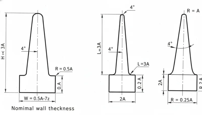
- Maintenez l'épaisseur de base des nervures à 50–60% de la paroi nominale pour éviter les retassures.
- Le temps de refroidissement augmente avec le carré de l'épaisseur de paroi — la conception en paroi mince offre un retour sur investissement élevé.
Ce guide couvre tout ce que les ingénieurs doivent savoir sur moulage par injection Épaisseur de paroi : comment choisir la bonne valeur, ce qui se passe lorsque les parois ne sont pas uniformes, recommandations spécifiques aux matériaux, et les erreurs les plus courantes tirées de milliers d'analyses DFM.
Qu'est-ce que l'épaisseur de paroi en moulage par injection ?
L'épaisseur de paroi est la distance entre les surfaces extérieure et intérieure d'une pièce moulée à toute section transversale. Elle détermine comment le plastique s'écoule dans la cavité du moule d'injection, à quelle vitesse la pièce refroidit et si les dimensions finales respectent les spécifications.
« La variation d'épaisseur de paroi doit rester dans une plage de ±25% de la valeur nominale. »Vrai
La directive de l'industrie est une variation de ±25% de l'épaisseur nominale. Dépasser cette limite sans transitions progressives entraîne un retrait différentiel, du gauchissement et une instabilité dimensionnelle.
« Une nervure dont l'épaisseur de base est égale à 80% de la paroi nominale ne causera pas de retassures. »Faux
Les nervures plus épaisses que 50 à 60 % de la paroi nominale produisent presque toujours des marques de retrait visibles, car la nervure crée un point chaud localisé qui refroidit beaucoup plus lentement que la paroi environnante.
Des parois plus minces économisent de la matière et réduisent le temps de cycle, mais augmentent les besoins en pression d'injection et le risque de pièces incomplètes. Des parois plus épaisses facilitent l'écoulement mais refroidissent lentement, prolongeant le temps de cycle et augmentant le risque de vides et de retassures. Le point idéal pour la plupart des thermoplastiques techniques est de 1,5 à 3,0 mm. Vérifiez toujours l'épaisseur choisie par rapport à la fiche technique du fournisseur de matière et aux résultats de simulation d'écoulement avant de finaliser la conception.
Pourquoi une épaisseur de paroi uniforme est-elle si importante ?
L'épaisseur de paroi non uniforme est la cause première de plus de défauts de moulage que toute autre erreur de conception. Lorsque les parois varient significativement, les sections épaisses refroidissent et se rétractent à un rythme différent des sections minces. Ce retrait différentielmoulage par injection[2] crée des contraintes internes qui se manifestent par du gauchissement, des retassures et une instabilité dimensionnelle.
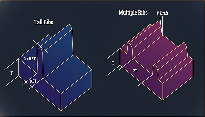
« Plusieurs nervures fines sont généralement préférables à une seule nervure haute et épaisse pour la rigidité. »Vrai
Plusieurs nervures fines répartissent uniformément les contraintes, refroidissent plus vite et produisent des retassures minimales, comparé à une seule nervure épaisse créant une masse thermique localisée.
« Une transition nette à 90° d'une paroi de 3 mm à 1,5 mm est acceptable si la section plus mince est courte. »Faux
Les transitions brusques créent des concentrations de contraintes quelle que soit la longueur. Elles provoquent des hésitations d'écoulement, augmentent les contraintes résiduelles et génèrent des défauts de surface visibles. Utilisez toujours un rapport de conicité de 3 : 1.
La directive est simple : maintenez l'épaisseur de paroi dans une plage de ±25% de la valeur nominale sur toute la pièce. Si votre paroi nominale est de 2,5 mm, chaque section doit se situer entre 1,9 mm et 3,1 mm.
Quelle est l'Épaisseur de Paroi Recommandée par Matériau ?
Différents matériaux ont des caractéristiques d'écoulement et des taux de retrait différents. Voici un tableau de référence pratique basé sur de nombreuses données de production.
| Matériau | Min Wall (mm) | Plage idéale (mm) | Max Pratique (mm) |
|---|---|---|---|
| ABS | 0.8 | 1.5–3.0 | 4.5 |
| PC (Polycarbonate) | 0.8 | 1.5–3.0 | 4.5 |
| PP (Polypropylène) | 0.6 | 1.2–2.5 | 5.0 |
| PA (Nylon 6/66) | 0.6 | 1.0–3.0 | 4.0 |
| POM (Acetal) | 0.8 | 1.0–3.0 | 4.0 |
| PMMA (Acrylic) | 0.8 | 1,5–3,5 | 5.0 |
| PBT | 0.8 | 1.0–3.0 | 4.0 |
| PE (Polyéthylène) | 0.6 | 1.0–2.5 | 5.0 |
| PS (Polystyrène) | 0.8 | 1.0–3.0 | 4.5 |
| TPE/TPU | 0.5 | 1.0–3.0 | 5.0 |
Les valeurs minimales d'épaisseur représentent ce qui est techniquement possible avec un procédé optimisé, et non ce qui est recommandé pour la production. Pour une fabrication fiable, restez dans la plage idéale.
Comment effectuer une transition entre différentes épaisseurs de paroi ?
Parfois, la variation d'épaisseur de paroi est inévitable. Lorsque cela se produit, la transition entre les sections épaisses et minces est critique. La directive standard est un rapport de conicité de 3:1 : pour chaque changement d'épaisseur de 1 mm, prévoir au moins 3 mm de transition progressive.
Les changements brusques d'épaisseur provoquent une hésitation d'écoulement, des concentrations de contraintes et des retassures visibles sur la surface opposée. Dans les cas graves, les pièces se fissurent aux transitions d'épaisseur lors de l'assemblage car la contrainte résiduelle dépasse la limite d'élasticité du matériau.
Que se passe-t-il lorsque les parois sont trop épaisses ?
Les parois épaisées créent trois problèmes : temps de cycle excessif, vides internes et marques d'affaissement.
Cycle Time Penalty
Le temps de refroidissement augmente approximativement avec le carré de l'épaisseur de paroi. Une pièce avec des parois de 2 mm peut refroidir en 15 secondes ; la même géométrie avec des parois de 4 mm pourrait prendre 50 à 60 secondes. Sur une production de 100 000 pièces, cela représente des milliers d'heures machine supplémentaires.
« Le temps de refroidissement évolue avec le carré de l'épaisseur de paroi — doubler l'épaisseur quadruple le temps de refroidissement. »Vrai
Cette relation non linéaire explique pourquoi la conception en paroi mince offre un retour sur investissement si élevé. Réduire l'épaisseur de 4 mm à 2 mm peut diminuer le temps de refroidissement de 75 %.
« Réduire l'épaisseur de paroi améliore toujours la qualité de la pièce et l'efficacité de la production. »Faux
Si les parois minces réduisent l'utilisation de matière et le temps de cycle, des parois trop fines provoquent des courts-circuits d'injection, augmentent les besoins en pression d'injection et compromettent l'intégrité structurelle. L'épaisseur optimale équilibre écoulement, résistance et coût.
Vides Internes
Lorsque les sections épaisses refroidissent, la peau extérieure se solidifie en premier tandis que l'intérieur est encore fondu. Lorsque l'intérieur se rétracte, il se détache de la peau solidifiée, créant des vides internes qui réduisent l'intégrité structurelle — particulièrement problématique dans les applications de charge.
Marques d'évier
Les marques de retrait sont la manifestation en surface du même phénomène. Lorsque le matériau d'une section épaisse se rétracte, il tire la surface vers l'intérieur, créant une dépression visible particulièrement notable sur les surfaces brillantes. Les ratios nervure/paroi contrôlent directement la sévérité du retrait : les nervures plus épaisses que 50–60 % de la paroi nominale produisent presque toujours des marques de retrait visibles.
Que Se Produit-il Lorsque les Parois sont Trop Fines ?
Les parois minces comportent leurs propres risques. Le plus immédiat est celui des courts-circuits — la matière plastique fondue gèle avant de remplir complètement la cavité. Ceci est particulièrement problématique avec les matériaux à haute viscosité comme le polycarbonate et les longs chemins d'écoulement, où la viscosité de la matière fondue est déjà élevée.
Les parois fines augmentent également les besoins de pression d'injection. Si la pression requise dépasse la capacité de la machine, vous obtenez des remplissages incomplets et un stress résiduel élevé.
L'intégrité structurelle est une autre préoccupation — incluez toujours une marge de sécurité pour les pièces à paroi fine dans les produits de consommation soumis aux tests de chute. Une pièce qui résiste aux charges statiques peut se fissurer lors d'un impact si les parois sont trop fines.
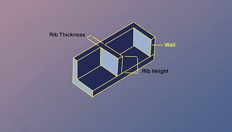
Comment les nervures et les bossages affectent-ils l'épaisseur de paroi ?
Les nervures et les bossages sont les caractéristiques les plus courantes qui interagissent avec l'épaisseur de la paroi. Pour les nervures : l'épaisseur de base doit être de 50–60% de la paroi nominale, la hauteur ne doit pas dépasser 3× la paroi nominale, et plusieurs nervures fines sont meilleures qu'une seule nervure haute et épaisse.
Pour les bossages, l'évidement est la solution — creuser le centre avec un poinçon de noyau pour maintenir une épaisseur de paroi uniforme. Le diamètre extérieur du bossage ne doit pas dépasser 2 à 3 fois le diamètre du trou. Les pièces qui respectent ces proportions de moulage par injection moule d'injection[3] moule proprement ; ceux qui dévient génèrent des problèmes de qualité persistants.
Comment l'épaisseur de paroi affecte-t-elle le temps de cycle ?
En moulage par injection, temps de refroidissement[4] représente généralement 50–70 % du temps de cycle total, régi par la section transversale la plus épaisse.
| Paroi nominale | Temps de refroidissement typique | Coût relatif du cycle |
|---|---|---|
| 1.5 mm | 8–12 secondes | 1.0× (baseline) |
| 2,0 mm | 12–18 secondes | 1,3× |
| 2.5 mm | 18–25 secondes | 1.6× |
| 3.0 mm | 25–35 secondes | 2,0× |
| 4.0 mm | 40–60 secondes | 3.0× |
Passer de parois de 2,0 mm à 3,0 mm double à peu près le coût de fabrication par pièce rien que par le temps de cycle. La conception en paroi mince, lorsque structurellement réalisable, est l'une des optimisations au ROI le plus élevé en moulage par injection.
Quelles sont les erreurs les plus courantes concernant l'épaisseur de paroi ?
- Négliger l'épaisseur uniforme. Les pièces conçues sans analyse d'épaisseur ont des zones 3× plus épaisse que la paroi nominale à côté de sections à moitié de la paroi nominale, provoquant des marques de retrait, des déformations et des temps de cycle prolongés.
- Épaississement excessif pour la résistance. Les ingénieurs ajoutent de la matière lorsqu'une nervure serait plus légère, plus rapide à produire et plus stable dimensionnellement.
- Ignorer les proportions des nervures. Les nervures à 80–100 % de la paroi nominale provoquent des marques de retrait profondes. La règle des 50–60 % s'applique à tous les matériaux.
- Transitions d'épaisseur abruptes. Les changements brusques sans conicité créent des points de concentration de stress et des défauts cosmétiques.
- Ne pas exécuter la simulation d'écoulement. Les outils modernes prédisent les schémas de remplissage, la pression et le refroidissement avec une grande précision. Omettre la simulation sur des pièces complexes est généralement une erreur.
Que Devriez-vous Vérifier Avant de Soumettre votre Conception ?
Avant de soumettre votre conception pour l’outillage, parcourez cette liste de vérification. Chaque élément prend quelques secondes à vérifier et peut éviter des révisions d’outillage coûteuses.
| Check Item | Critères de validation |
|---|---|
| Mur nominal dans la plage idéale du matériau | ✓ |
| Variation du mur dans ±25% de l’épaisseur nominale | ✓ ou indiqué |
| Toutes nervures ≤60% de l’épaisseur nominale du mur | ✓ |
| Les transitions d’épaisseur utilisent un ratio 3:1 | ✓ |
| BOSS OD ≤3× diamètre du trou | ✓ |
| Section la plus épaisse identifiée et vérifiée | ✓ |
| Simulation de flux terminée | ✓ |
Optimiser l’épaisseur du mur avant la construction du moule est essentiel — le lieu le moins cher pour corriger un problème d’épaisseur est dans le CAO, pas dans l’acier.
Questions fréquemment posées sur l'épaisseur de paroi
Quelle est l'épaisseur minimale de paroi pour le moulage par injection ?
Pour la plupart des thermoplastiques techniques (ABS, PC, Nylon), 0,8 mm est le minimum pratique pour des chemins de flux courts. Pour les matériaux à haut flux comme PP et PE, vous pouvez descendre jusqu’à 0,5 mm. Ces minima nécessitent une pression d’injection élevée et comportent un risque de remplissage incomplet.
L'épaisseur des parois peut-elle varier sur une pièce ?
Oui, mais la variation doit rester dans les limites de ±25% de la paroi nominale, avec des transitions graduelles utilisant un rapport de conicité de 3:1 entre les différentes épaisseurs.
Comment l'épaisseur de paroi est-elle liée au retrait ?
Les sections plus épaisses rétrécissent davantage car plus de matière refroidit et se contracte. Ce retrait différentiel est la principale cause de déformation dans les pièces moulées par injection.
L'épaisseur de la paroi affecte-t-elle la résistance de la pièce ?
Oui, mais pas linéairement. Doubler l’épaisseur du mur augmente plus que double la rigidité en flexion (elle varie avec l’épaisseur au cube). Cependant, augmenter l’épaisseur des murs augmente aussi la contrainte résiduelle et le risque de vide. Des nervures proportionnées correctement offrent souvent une meilleure performance poids/force.
Comment mesurer l'épaisseur de paroi ?
Utilisez les outils d'analyse d'épaisseur dans votre logiciel de CAO (SolidWorks, Creo et la plupart des logiciels MCAD les intègrent). Sur les pièces physiques, les jauges d'épaisseur à ultrasons fournissent une mesure non destructive, ou coupez des sections transversales pour une mesure directe avec des pieds à coulisse. En production, la jauge à ultrasons est la méthode standard pour la surveillance continue de la qualité.
Qu'est-ce que le Moulage à Paroi Fine ?
Le moulage à paroi mince désigne les pièces dont l'épaisseur de paroi est inférieure à 1,0 mm (parfois aussi fine que 0,3 mm pour les boîtiers électroniques). Il nécessite des machines à grande vitesse capables de très hautes pressions (200+ MPa) et une conception de moule spécialisée.
Bottom line: Maintenez l'épaisseur de paroi entre 1,5 et 3,0 mm, assurez une uniformité de ±25%, utilisez des transitions coniques de 3:1, et gardez les nervures à 50–60% de l'épaisseur nominale. Ces quatre règles préviennent 90% des défauts liés à l'épaisseur de paroi.
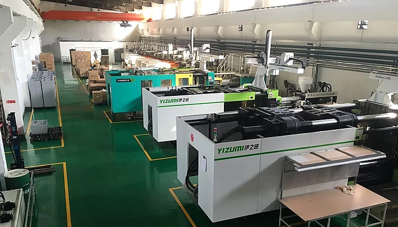
Les décisions concernant l'épaisseur des parois prises tôt dans la conception déterminent si votre pièce moule efficacement ou vous pose des problèmes tout au long de la production. Si vous souhaitez une revue de conception pour la fabrication par des ingénieurs qui ont optimisé des milliers de conceptions d'épaisseur de paroi sur plus de 400 matériaux, contactez notre équipe chez ZetarMold. Nous exploitons 45 machines de moulage par injection (90T–1850T) depuis notre site de Shanghai, avec plus de 30 chefs de projet anglophones prêts à vous aider.
-
Conception de l'épaisseur de la paroi — BASF, « Conception de pièces et de moules », Manuel de technologie des plastiques, 2023. ↩
-
Retrait différentiel — Autodesk, « Guide de conception Moldflow », 2024. ↩
-
Lignes directrices de conception — « Bonnes pratiques pour l'épaisseur de paroi », Society of Plastics Engineers, 2025. ↩
-
Temps de refroidissement — « Optimisation du refroidissement en moulage par injection », Plastics Technology, 2024. ↩


