 Ir al contenido

Grosor de la pared[1] is arguably the single most important design parameter in injection molding. Get it right, and your part molds cleanly, functions reliably, and costs less. Get it wrong, and you’re dealing with sink marks, warpage, voids, and cycle times that eat your margin.
Key Takeaways:
- Keep nominal wall thickness between 1.5–3.0 mm for most engineering thermoplastics.
- Maintain wall variation within ±25% of the nominal value throughout the part.
- Use 3:1 taper ratio for transitions between different wall thicknesses.
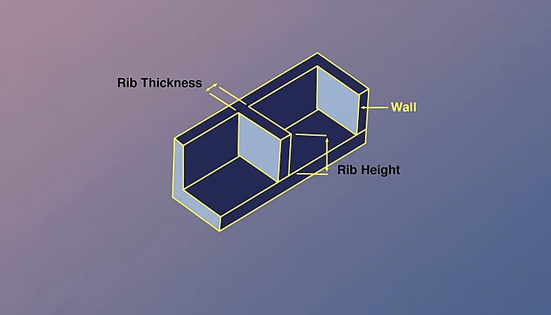
- Keep rib base thickness at 50–60% of nominal wall to avoid sink marks.
- Cooling time scales with the square of wall thickness — thin-wall design has high ROI.
This guide covers everything engineers need to know about moldeo por inyección wall thickness: how to choose the right value, what happens when walls aren’t uniform, material-specific guidelines, and the most common mistakes from thousands of DFM reviews.
What Is Wall Thickness in Injection Molding?
Wall thickness is the distance between the outer and inner surface of a molded part at any cross-section. It determines how plastic flows through the injection mold cavity, how quickly the part cools, and whether final dimensions hold to specification.
“Wall thickness variation should stay within ±25% of the nominal value.”Verdadero
The industry guideline is ±25% variation. Exceeding this without gradual transitions causes differential shrinkage, warpage, and dimensional instability.
“A rib with base thickness equal to 80% of the nominal wall will not cause sink marks.”Falso
Ribs thicker than 50–60% of nominal wall almost always produce visible sink marks because the rib creates a localized hot spot that cools much slower than the surrounding wall.
Thinner walls save material and reduce cycle time, but increase injection pressure requirements and risk short shots. Thicker walls flow more easily but cool slowly, extending cycle time and increasing the risk of voids and sink marks. The sweet spot for most engineering thermoplastics is 1.5–3.0 mm. Always verify your chosen thickness against the material supplier’s data sheet and flow simulation results before finalizing the design.
Why Is Uniform Wall Thickness So Important?
Non-uniform wall thickness is the root cause of more molding defects than any other single design error. When walls vary significantly, thick sections cool and shrink at a different rate than thin sections. This differential shrinkagemoldeo por inyección[2] creates internal stresses that manifest as warpage, sink marks, and dimensional instability.
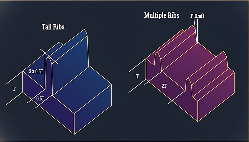
“Multiple thin ribs are generally better than one tall, thick rib for stiffness.”Verdadero
Multiple thin ribs distribute stress evenly, cool faster, and produce minimal sink marks compared to a single thick rib creating a localized thermal mass.
“A sharp 90° transition from 3 mm to 1.5 mm wall is acceptable if the thinner section is short.”Falso
Abrupt transitions create stress concentrations regardless of length. They cause flow hesitation, increased residual stress, and visible surface defects. Always use the 3:1 taper ratio.
The guideline is straightforward: maintain wall thickness within ±25% of the nominal value throughout the entire part. If your nominal wall is 2.5 mm, every section should fall between 1.9 mm and 3.1 mm.
What Is the Recommended Wall Thickness by Material?
Different materials have different flow characteristics and shrinkage rates. Here’s a practical reference table based on extensive production data.
| Material | Min Wall (mm) | Ideal Range (mm) | Max Practical (mm) |
|---|---|---|---|
| ABS | 0.8 | 1.5–3.0 | 4.5 |
| PC (policarbonato) | 0.8 | 1.5–3.0 | 4.5 |
| PP (polipropileno) | 0.6 | 1.2–2.5 | 5.0 |
| PA (Nylon 6/66) | 0.6 | 1.0–3.0 | 4.0 |
| POM (Acetal) | 0.8 | 1.0–3.0 | 4.0 |
| PMMA (Acrylic) | 0.8 | 1.5–3.5 | 5.0 |
| PBT | 0.8 | 1.0–3.0 | 4.0 |
| PE (polietileno) | 0.6 | 1.0–2.5 | 5.0 |
| PS (Poliestireno) | 0.8 | 1.0–3.0 | 4.5 |
| TPE/TPU | 0.5 | 1.0–3.0 | 5.0 |
The minimum wall values represent what’s technically possible with optimized processing, not what’s recommended for production. For reliable manufacturing, stay within the ideal range.
How Do You Transition Between Different Wall Thicknesses?
Sometimes wall thickness variation is unavoidable. When it happens, the transition between thick and thin sections is critical. The standard guideline is a 3:1 taper ratio: for every 1 mm of thickness change, provide at least 3 mm of gradual transition.
Abrupt thickness changes cause flow hesitation, stress concentrations, and visible sink marks on the opposite surface. In severe cases, parts crack at thickness transitions during assembly because residual stress exceeds the material’s yield strength.
What Happens When Walls Are Too Thick?
Thick walls create three problems: excessive cycle time, internal voids, and sink marks.
Cycle Time Penalty
Cooling time scales approximately with the square of wall thickness. A part with 2 mm walls might cool in 15 seconds; the same geometry with 4 mm walls could take 50–60 seconds. Across a production run of 100,000 parts, that’s thousands of additional machine hours.
“Cooling time scales with the square of wall thickness — doubling wall quadruples cooling time.”Verdadero
This non-linear relationship is why thin-wall design has such high ROI. Reducing wall from 4mm to 2mm can cut cooling time by 75%.
“Reducing wall thickness always improves part quality and production efficiency.”Falso
While thin walls reduce material usage and cycle time, walls that are too thin cause short shots, increase injection pressure requirements, and compromise structural integrity. The optimal thickness balances flow, strength, and cost.
Internal Voids
When thick sections cool, the outer skin solidifies first while the interior is still molten. As the interior shrinks, it pulls away from the solidified skin, creating internal voids that reduce structural integrity — particularly problematic in load-bearing applications.
Marcas de fregadero
Sink marks are the surface manifestation of the same phenomenon. When material at a thick section shrinks, it pulls the surface inward, creating a visible depression especially noticeable on glossy surfaces. Rib-to-wall ratios directly control sink severity: ribs thicker than 50–60% of nominal wall almost always produce visible sink marks.
What Happens When Walls Are Too Thin?
Thin walls carry their own risks. The most immediate is short shots — the plastic melt freezes before completely filling the cavity. This is especially problematic with high-viscosity materials like polycarbonate and long flow paths, where the melt viscosity is already high.
Thin walls also increase injection pressure requirements. If required pressure exceeds machine capability, you get incomplete fills and high residual stress.
Structural integrity is another concern — always include a safety margin for thin-wall parts in consumer products subject to drop testing. A part that survives static loads may crack on impact if walls are too thin.
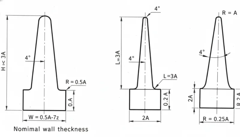
¿Cómo Afectan las Nervaduras y los Resaltos el Espesor de Pared?
Las nervaduras y resaltos son los elementos más comunes que interactúan con el espesor de pared. Para nervaduras: el espesor base debe ser 50–60% de la pared nominal, la altura no debe exceder 3× la pared nominal, y múltiples nervaduras delgadas son mejores que una sola nervadura alta y gruesa.
Para resaltos, el aligerado es la solución — vaciar el centro con un núcleo para mantener un espesor de pared uniforme. El diámetro exterior del resalto no debe ser más de 2–3 veces el diámetro del agujero. Las piezas que siguen estas proporciones de moldeo por inyección molde de inyección[3] el molde limpiamente; aquellos que se apartan generan problemas de calidad continuos.
¿Cómo afecta el grosor de la pared el tiempo de ciclo?
En moldeo por inyección, tiempo de enfriamiento[4] típicamente representa 50–70% del tiempo total de ciclo, gobernado por la sección transversal más gruesa.
| Grosor Nominal | Tiempo de Refrigeración Típico | Costo Relativo de Ciclo |
|---|---|---|
| 1.5 mm | 8–12 segundos | 1.0× (referencia) |
| 2.0 mm | 12–18 segundos | 1.3× |
| 2.5 mm | 18–25 segundos | 1.6× |
| 3.0 mm | 25–35 segundos | 2.0× |
| 4.0 mm | 40–60 segundos | 3.0× |
Pasar de paredes de 2.0 mm a 3.0 mm aproximadamente duplica el costo de fabricación por pieza solo por el tiempo de ciclo. El diseño de paredes finas, cuando es estructuralmente viable, es una de las optimizaciones de mayor ROI en la moldura por inyección.
¿Cuáles Son los Errores Más Comunes en Espesor de Pared?
- Desatender el espesor uniforme. Las piezas diseñadas sin análisis de grosor tienen áreas 3× más gruesas que el nominal junto a secciones con la mitad del grosor nominal, causando marcas de hundimiento, deformación y tiempos de ciclo prolongados.
- Sobreespesar para resistencia. Los ingenieros añaden material cuando un nervio sería más ligero, más rápido de producir y más dimensionalmente estable.
- Ignorar las proporciones de las nervaduras. Los nervios a 80–100% del grosor nominal causan marcas de hundimiento profundas. La regla de 50–60% aplica a cada material.
- Transiciones abruptas de grosor. Los cambios bruscos sin conicidad crean concentradores de tensión y defectos cosméticos.
- No ejecutar simulación de flujo. Las herramientas modernas predicen patrones de llenado, presión y enfriamiento con alta precisión. Omitir la simulación en piezas complejas generalmente resulta en pérdidas.
¿Qué Debes Verificar Antes de Enviar tu Diseño?
Antes de enviar su diseño para la fabricación de moldes, revise esta lista de verificación. Cada elemento toma segundos para verificar y puede evitar revisiones costosas de los moldes.
| Check Item | Criterios de Aprobación |
|---|---|
| Pared nominal dentro del rango ideal del material | ✓ |
| Variación de pared dentro de ±25% de la nominal | ✓ o indicado |
| Todas las nervaduras ≤60% de la pared nominal | ✓ |
| Las transiciones de grosor utilizan una inclinación de 3:1 | ✓ |
| OD del refuerzo ≤3× diámetro del orificio | ✓ |
| Sección más gruesa identificada y revisada | ✓ |
| Simulación de flujo completada | ✓ |
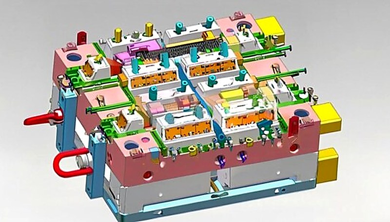
Optimizar el grosor de la pared antes de construir el molde es esencial — el lugar más económico para solucionar un problema de grosor es en CAD, no en acero.
Preguntas Frecuentes sobre el Grosor de la Pared
¿Cuál es el grosor mínimo de pared para el moldeo por inyección?
Para la mayoría de los termoplásticos de ingeniería (ABS, PC, Nylon), 0.8 mm es el mínimo práctico para trayectorias de flujo cortas. Para materiales de alto flujo como PP y PE, se puede llegar hasta 0.5 mm. Estos mínimos requieren alta presión de inyección y conllevan riesgo de piezas incompletas.
¿Puede variar el espesor de la pared en una pieza?
Sí, pero la variación debe mantenerse dentro de ±25% de la pared nominal, con transiciones graduales usando una relación de conicidad de 3:1 entre diferentes espesores.
¿Cómo se relaciona el espesor de la pared con la contracción?
Las secciones más gruesas se encogen más porque más material se está enfriando y contrayendo. Esta contracción diferencial es la causa principal de la deformación en las piezas moldeadas por inyección.
¿El Grosor de la Pared Afecta la Resistencia de la Pieza?
Sí, pero no de forma lineal. Duplicar el espesor de pared más que duplica la rigidez a flexión (escala con el cubo del espesor). Sin embargo, aumentar el espesor de las paredes también incrementa la tensión residual y el riesgo de huecos. Las nervaduras correctamente proporcionadas a menudo logran un mejor rendimiento de resistencia-peso.
¿Cómo se Mide el Espesor de Pared?
Utilice herramientas de análisis de espesor en su software CAD (SolidWorks, Creo y la mayoría de paquetes MCAD las tienen integradas). En piezas físicas, los medidores de espesor ultrasónicos proporcionan medición no destructiva, o corte secciones transversales para medición directa con calibradores. Durante la producción, la medición ultrasónica es el método estándar para el monitoreo continuo de calidad.
¿Qué es el moldeo de pared delgada?
El moldeo de pared delgada se refiere a piezas con espesor de pared inferior a 1,0 mm (a veces tan delgado como 0,3 mm para carcasas de electrónica). Requiere máquinas de alta velocidad capaces de presiones muy altas (200+ MPa) y diseño de molde especializado.
Bottom line: Mantenga el espesor de pared entre 1,5–3,0 mm, mantenga una uniformidad de ±25%, use transiciones cónicas de 3:1 y mantenga las nervaduras al 50–60% del espesor nominal de pared. Estas cuatro reglas previenen el 90% de los defectos relacionados con el espesor de pared.
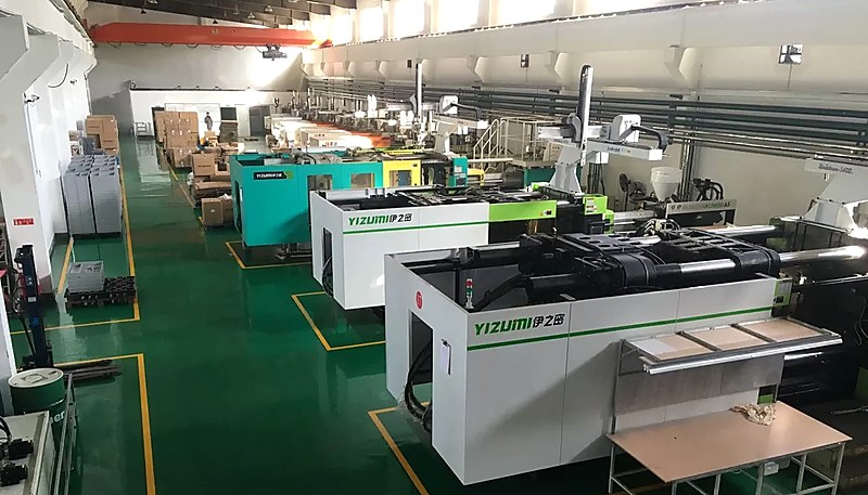
Las decisiones sobre el espesor de pared tomadas al inicio del diseño determinan si su pieza se moldea eficientemente o presenta problemas durante toda la producción. Si desea una revisión de DFM de ingenieros que han optimizado miles de diseños de espesor de pared en más de 400 materiales, comuníquese con nuestro equipo en ZetarMold. Operamos 45 máquinas de moldeo por inyección (90T–1850T) desde nuestras instalaciones en Shanghái, con más de 30 gerentes de proyecto de habla inglesa listos para ayudar.
-
Diseño del grosor de la pared — BASF, “Diseño de Pieza y Molde,” Manual de Tecnología de Plásticos, 2023. ↩
-
Contracción diferencial — Autodesk, “Guía de Diseño Moldflow,” 2024. ↩
-
Pautas de diseño — “Mejores Prácticas de Espesor de Pared,” Sociedad de Ingenieros Plásticos, 2025. ↩
-
Tiempo de enfriamiento — “Optimización del Refrigeración en Moldes por Inyección,” Tecnología de Plásticos, 2024. ↩


