 Vai al contenuto

Spessore della parete[1] è probabilmente il singolo parametro di progettazione più importante nello stampaggio a iniezione. Se è corretto, il pezzo si stampa bene, funziona in modo affidabile e costa meno. Se è sbagliato, si devono affrontare avvallamenti, deformazioni, vuoti e tempi di ciclo che erodono il margine.
Punti Chiave:
- Mantenere lo spessore nominale della parete tra 1,5–3,0 mm per la maggior parte delle termoplastiche tecniche.
- Mantenere la variazione dello spessore entro ±25% del valore nominale in tutto il pezzo.
- Utilizzare un rapporto di conicità 3:1 per le transizioni tra diversi spessori di parete.
- Mantenere lo spessore della base delle nervature al 50-60% dello spessore nominale della parete per evitare segni di affondamento.
- Il tempo di raffreddamento scala con il quadrato dello spessore della parete — la progettazione a parete sottile ha un alto ROI.
Questa guida copre tutto ciò che gli ingegneri devono sapere su stampaggio a iniezione spessore della parete: come scegliere il valore giusto, cosa succede quando le pareti non sono uniformi, linee guida specifiche per materiale e gli errori più comuni da migliaia di revisioni DFM.
Cos'è lo spessore della parete nello stampaggio a iniezione?
Lo spessore della parete è la distanza tra la superficie esterna e interna di un pezzo stampato in qualsiasi sezione trasversale. Determina come la plastica scorre attraverso la cavità dello stampo a iniezione, quanto velocemente il pezzo si raffredda e se le dimensioni finali rispettano le specifiche.
“La variazione dello spessore della parete dovrebbe rimanere entro ±25% del valore nominale.”Vero
La linea guida del settore è una variazione di ±25%. Superare questo limite senza transizioni graduali provoca ritiro differenziale, deformazione e instabilità dimensionale.
“Una nervatura con spessore di base pari all'80% della parete nominale non causerà avvallamenti.”Falso
Le nervature più spesse del 50–60% dello spessore nominale della parete producono quasi sempre aloni visibili perché la nervatura crea un punto caldo localizzato che si raffredda molto più lentamente della parete circostante.
Le pareti più sottili risparmiano materiale e riducono il tempo di ciclo, ma aumentano i requisiti di pressione di iniezione e il rischio di iniezioni incomplete. Le pareti più spesse fluiscono più facilmente ma raffreddano lentamente, prolungando il tempo di ciclo e aumentando il rischio di vuoti e avvallamenti. Il punto ottimale per la maggior parte dei termoplastici tecnici è 1,5–3,0 mm. Verificare sempre lo spessore scelto rispetto alla scheda tecnica del fornitore del materiale e ai risultati della simulazione di flusso prima di finalizzare il progetto.
Perché l'uniformità dello spessore della parete è così importante?
Lo spessore non uniforme della parete è la causa principale di più difetti di stampaggio rispetto a qualsiasi altro singolo errore di progettazione. Quando le pareti variano significativamente, le sezioni spesse si raffreddano e si restringono a una velocità diversa rispetto alle sezioni sottili. Questo restringimento differenzialestampaggio a iniezione[2] crea tensioni interne che si manifestano come deformazione, avvallamenti e instabilità dimensionale.
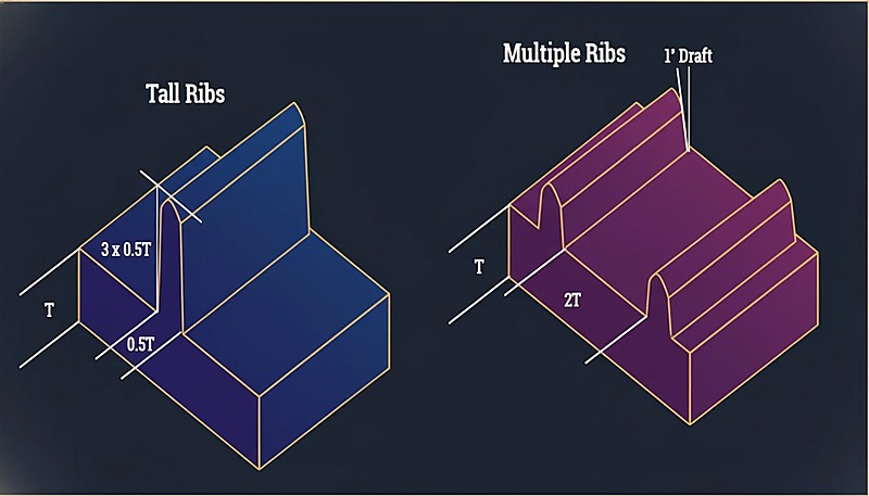
“In genere, più nervature sottili sono migliori di una nervatura alta e spessa per la rigidità.”Vero
Molte nervature sottili distribuiscono lo stress in modo uniforme, raffreddano più velocemente e producono aloni minimi rispetto a una singola nervatura spessa che crea una massa termica localizzata.
"Una transizione netta a 90° da 3 mm a 1,5 mm di spessore è accettabile se la sezione più sottile è breve."Falso
Le transizioni brusche creano concentrazioni di stress indipendentemente dalla lunghezza. Causano esitazione del flusso, aumento dello stress residuo e difetti superficiali visibili. Utilizzare sempre il rapporto di conicità 3:1.
La linea guida è semplice: mantenere lo spessore della parete entro ±25% del valore nominale in tutta la parte. Se lo spessore nominale della parete è di 2,5 mm, ogni sezione dovrebbe essere compresa tra 1,9 mm e 3,1 mm.
Qual è lo Spessore di Parete Consigliato per Materiale?
Materiali diversi hanno caratteristiche di flusso e tassi di ritiro diversi. Ecco una tabella di riferimento pratica basata su dati di produzione estesi.
| Materiale | Min Wall (mm) | Intervallo ideale (mm) | Massimo pratico (mm) |
|---|---|---|---|
| ABS | 0.8 | 1.5–3.0 | 4.5 |
| PC (policarbonato) | 0.8 | 1.5–3.0 | 4.5 |
| PP (polipropilene) | 0.6 | 1,2–2,5 | 5.0 |
| PA (Nylon 6/66) | 0.6 | 1.0–3.0 | 4.0 |
| POM (Acetal) | 0.8 | 1.0–3.0 | 4.0 |
| PMMA (Acrylic) | 0.8 | 1,5–3,5 | 5.0 |
| PBT | 0.8 | 1.0–3.0 | 4.0 |
| PE (polietilene) | 0.6 | 1.0–2.5 | 5.0 |
| PS (polistirolo) | 0.8 | 1.0–3.0 | 4.5 |
| TPE/TPU | 0.5 | 1.0–3.0 | 5.0 |
I valori minimi di spessore rappresentano ciò che è tecnicamente possibile con una lavorazione ottimizzata, non ciò che è consigliato per la produzione. Per una produzione affidabile, rimanere entro l'intervallo ideale.
Come si effettua la transizione tra diversi spessori di parete?
A volte la variazione dello spessore della parete è inevitabile. Quando ciò accade, la transizione tra sezioni spesse e sottili è critica. La linea guida standard è un rapporto di conicità 3:1: per ogni 1 mm di variazione di spessore, fornire almeno 3 mm di transizione graduale.
I cambiamenti bruschi di spessore causano esitazione del flusso, concentrazioni di stress e aloni visibili sulla superficie opposta. Nei casi più gravi, i pezzi si rompono alle transizioni di spessore durante il montaggio perché lo stress residuo supera la resistenza allo snervamento del materiale.
Cosa Succede Quando le Pareti Sono Troppo Spesse?
Le pareti spesse creano tre problemi: tempo di ciclo eccessivo, vuoti interni e aloni.
Cycle Time Penalty
Il tempo di raffreddamento scala approssimativamente con il quadrato dello spessore della parete. Una parte con pareti di 2 mm potrebbe raffreddarsi in 15 secondi; la stessa geometria con pareti di 4 mm potrebbe richiedere 50-60 secondi. In una produzione di 100.000 parti, ciò significa migliaia di ore macchina aggiuntive.
"Il tempo di raffreddamento scala con il quadrato dello spessore della parete — raddoppiare lo spessore quadruplica il tempo di raffreddamento."Vero
Questa relazione non lineare spiega perché la progettazione a parete sottile ha un ROI così elevato. Ridurre la parete da 4 mm a 2 mm può tagliare il tempo di raffreddamento del 75%.
“Ridurre lo spessore della parete migliora sempre la qualità del pezzo e l'efficienza produttiva.”Falso
Mentre le pareti sottili riducono l'uso di materiale e il tempo di ciclo, pareti troppo sottili causano iniezioni incomplete, aumentano i requisiti di pressione di iniezione e compromettono l'integrità strutturale. Lo spessore ottimale bilancia flusso, resistenza e costo.
Vuoti Interni
Quando le sezioni spesse si raffreddano, la pelle esterna si solidifica per prima mentre l'interno è ancora fuso. Mentre l'interno si contrae, si stacca dalla pelle solidificata, creando vuoti interni che riducono l'integrità strutturale — particolarmente problematico nelle applicazioni portanti.
Segni di lavandino
I segni di ritiro sono la manifestazione superficiale dello stesso fenomeno. Quando il materiale in una sezione spessa si ritira, tira la superficie verso l'interno, creando una depressione visibile particolarmente evidente su superfici lucide. I rapporti nervatura-spessore controllano direttamente la gravità del ritiro: nervature più spesse del 50–60% dello spessore nominale producono quasi sempre segni di ritiro visibili.
Cosa succede quando le pareti sono troppo sottili?
Le pareti sottili comportano rischi propri. Il più immediato è il mancato riempimento — il fuso plastico si solidifica prima di riempire completamente la cavità. Ciò è particolarmente problematico con materiali ad alta viscosità come il policarbonato e percorsi di flusso lunghi, dove la viscosità del fuso è già elevata.
Le pareti sottili aumentano anche i requisiti di pressione di iniezione. Se la pressione richiesta supera la capacità della macchina, si ottengono riempimenti incompleti e alta tensione residua.
L'integrità strutturale è un'altra preoccupazione — includi sempre un margine di sicurezza per parti a parete sottile in prodotti consumer soggetti a test di caduta. Una parte che resiste a carichi statici potrebbe rompersi all'impatto se le pareti sono troppo sottili.
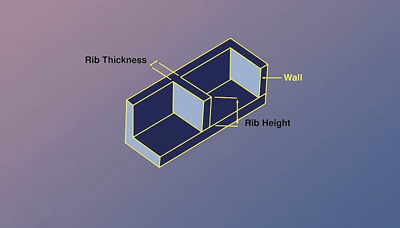
Come Influiscono Nervature e Rinforzi sullo Spessore della Parete?
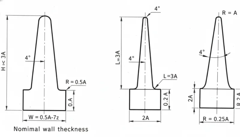
Le nervature e i boss sono le caratteristiche più comuni che interagiscono con lo spessore della parete. Per le nervature: lo spessore di base dovrebbe essere il 50–60% dello spessore nominale, l'altezza non dovrebbe superare 3× lo spessore nominale, e più nervature sottili sono meglio di una nervatura alta e spessa.
Per i boss, la perforazione è la soluzione — svuota il centro con un pin di nucleo per mantenere uno spessore uniforme della parete. Il diametro esterno del boss non dovrebbe essere più di 2–3 volte il diametro del foro. Parti che seguono queste proporzioni dello stampaggio a iniezione stampo a iniezione[3] stampano pulito; quelle che deviano generano problemi di qualità persistenti.
Come Influisce lo Spessore della Parete sul Tempo di Ciclo?
In stampaggio a iniezione, tempo di raffreddamento[4] tipicamente rappresenta il 50–70% del tempo totale del ciclo, governato dalla sezione trasversale più spessa.
| Spessore Nominale | Tempo di Raffreddamento Tipico | Costo Relativo del Ciclo |
|---|---|---|
| 1.5 mm | 8–12 secondi | 1,0× (baseline) |
| 2.0 mm | 12–18 secondi | 1.3× |
| 2,5 mm | 18–25 secondi | 1.6× |
| 3.0 mm | 25–35 secondi | 2.0× |
| 4.0 mm | 40–60 secondi | 3.0× |
Passare da pareti di 2,0 mm a 3,0 mm raddoppia circa il costo di produzione per parte solo attraverso il tempo di ciclo. Il design a parete sottile, quando strutturalmente possibile, è una delle ottimizzazioni con ROI più alto nello stampaggio a iniezione.
Quali sono gli errori più comuni sullo spessore della parete?
- Trascurare lo spessore uniforme. Parti progettate senza analisi dello spessore hanno aree 3 volte più spesse rispetto al nominale insieme a sezioni a metà della parete nominale, causando segni di affondamento, deformazione e tempi di ciclo prolungati.
- Sovradimensionamento per la resistenza. Gli ingegneri aggiungono materiale quando una nervatura sarebbe più leggera, più veloce da produrre e più stabile dimensionalmente.
- Ignorare le proporzioni delle nervature. Le nervature all'80–100% dello spessore nominale causano marcati segni di ritiro. La regola del 50–60% si applica a ogni materiale.
- Transizioni di spessore brusche. I cambiamenti bruschi senza conicità creano concentratori di sollecitazione e difetti estetici.
- Non eseguire la simulazione di flusso. Gli strumenti moderni prevedono i pattern di riempimento, la pressione e il raffreddamento con alta precisione. Saltare la simulazione su parti complesse generalmente comporta perdite.
Cosa Dovresti Controllare Prima di Inviare il Tuo Disegno?
Prima di sottoporre il tuo progetto per la produzione degli stampi, esamina questa lista di controllo. Ogni elemento richiede pochi secondi per essere verificato e può evitare revisioni costose degli stampi.
| Check Item | Criteri di superamento |
|---|---|
| Spessore nominale entro l'intervallo ideale del materiale | ✓ |
| Variazione della parete entro ±25% del nominale | ✓ o annotato |
| Tutte le nervature ≤60% dello spessore nominale | ✓ |
| Le transizioni di spessore utilizzano una pendenza di 3:1 | ✓ |
| Diametro esterno del boss ≤3× diametro del foro | ✓ |
| Sezione più spessa identificata e revisionata | ✓ |
| Simulazione di flusso completata | ✓ |
Ottimizzare lo spessore della parete prima che lo stampo sia costruito è essenziale — il posto più economico per risolvere un problema di spessore è nel CAD, non nell'acciaio.
Domande Frequenti sullo Spessore della Parete
Qual è lo spessore minimo della parete per lo stampaggio a iniezione?
Per la maggior parte dei termoplastici tecnici (ABS, PC, Nylon), 0,8 mm è il minimo pratico per percorsi di flusso brevi. Per materiali ad alto flusso come PP e PE, puoi scendere fino a 0,5 mm. Questi minimi richiedono alta pressione di iniezione e comportano il rischio di mancato riempimento.
Lo Spessore della Parete Può Variare Attraverso un Pezzo?
Sì, ma la variazione deve rimanere entro ±25% della parete nominale, con transizioni graduali utilizzando un rapporto di conicità 3:1 tra spessori diversi.
Come Lo Spessore della Parete È Correlato al Ritiro?
Le sezioni più spesse si riducono maggiormente perché più materiale si raffredda e contrae. Questo differenziale di riduzione è la causa principale della deformazione nelle parti stampate a iniezione.
La Spessore del Muro Influisce sulla Resistenza del Componente?
Sì, ma non linearmente. Raddoppiare lo spessore della parete più che raddoppia la rigidità alla flessione (scala con il cubo dello spessore). Tuttavia, ispessire le pareti aumenta anche lo stress residuo e il rischio di vuoti. Nervature proporzionate correttamente spesso offrono una migliore resistenza rispetto al peso.
Come si Misura lo Spessore della Parete?
Utilizza gli strumenti di analisi dello spessore nel tuo software CAD (SolidWorks, Creo e la maggior parte dei pacchetti MCAD li hanno integrati). Su parti fisiche, gli spessimetri a ultrasuoni forniscono misurazioni non distruttive, oppure taglia sezioni trasversali per misurazioni dirette con calibri. Durante la produzione, la misurazione a ultrasuoni è il metodo standard per il monitoraggio continuo della qualità.
Cos'è lo Stampaggio a Parete Sottile?
Lo stampaggio a parete sottile si riferisce a parti con spessore della parete inferiore a 1,0 mm (a volte fino a 0,3 mm per gli alloggiamenti elettronici). Richiede macchine ad alta velocità in grado di pressioni molto elevate (200+ MPa) e un design dello stampo specializzato.
Bottom line: Mantieni lo spessore della parete tra 1,5–3,0 mm, mantieni una uniformità di ±25%, utilizza transizioni con conicità 3:1 e mantieni le nervature al 50–60% dello spessore nominale. Queste quattro regole prevengono il 90% dei difetti legati allo spessore della parete.
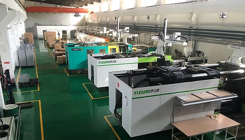
Le decisioni sullo spessore della parete prese all'inizio della progettazione determinano se la tua parte si stampa in modo efficiente o ti crea problemi durante tutta la produzione. Se desideri una revisione DFM da ingegneri che hanno ottimizzato migliaia di progetti di spessore della parete su oltre 400 materiali, contatta il nostro team presso ZetarMold. Operiamo con 45 macchine per lo stampaggio a iniezione (90T–1850T) dalla nostra struttura di Shanghai, con oltre 30 project manager di lingua inglese pronti ad aiutare.
-
Design dello spessore della parete — BASF, “Part and Mold Design,” Plastics Technology Handbook, 2023. ↩
-
Ritiro differenziale — Autodesk, “Moldflow Design Guide,” 2024. ↩
-
Linee guida di progettazione — “Wall Thickness Best Practices,” Society of Plastics Engineers, 2025. ↩
-
Tempo di raffreddamento — “Injection Molding Cooling Optimization,” Plastics Technology, 2024. ↩


