 Перейти к содержанию

- Скорость закрытия пресс-формы соответствует двухступенчатому профилю. Стадия подхода: быстрый закрытие от 200-300 мм/с до расстояния между поверхностями пресс-формы 5-10 мм. Стадия позиционирования: медленное закрытие от 5-10 мм/с для окончательного закрытия для защиты поверхностей пресс-формы и элементов центровки. Некоторые современные машины добавляют третью ступень защиты низкого давления на 1-2 мм/с с давлением зажима 5-10 бар перед полным зажимом. Это предотвращает повреждение, если посторонний материал или застрявшая деталь остаются в полости пресс-формы.
- Material drying is mandatory for hygroscopic plastics like PA6 and PEEK
- Cycle time breakdown: injection 10%, cooling 60-80%, ejection 5-15%
- Clamp force must exceed injection pressure by 20-30% to avoid flash
- Proper cooling design reduces cycle time by 20-35% versus conventional channels
- Ejection force should be 1.5-2 times the projected part area
- Quality inspection follows each shot: visual, dimensional, and functional checks
Step 1: What Is DFM Review and Why Does It Matter?
Your part geometry is frozen. The tooling quote is on your desk. Before steel cutting starts, there is one decision that determines first-shot success: Design for Manufacturability (DFM) review. We have run DFM checks on over 5,000 projects since 2005, and roughly 40% of first-shot failures trace back to wall thickness over 4mm with inadequate cooling. Fixing these after tooling costs ten times more. For more on проектирование пресс-форм fundamentals, see our mold guide.
At ZetarMold, our DFM workflow has been refined over 20 years of mold building. We process 400+ materials and build 100+ molds per month, so we see this tradeoff often. Our team includes 8 senior mold engineers who review every new part for wall thickness uniformity, gate placement optimization, and cooling channel efficiency before tooling approval.
“DFM review eliminates 80% of potential injection molding defects.”Правда
By catching wall thickness variations, insufficient draft angles, and gate location issues before steel cutting, manufacturers avoid sink marks, warpage, and short shots that typically require mold modifications costing $5,000-$50,000 per change.
“All wall thickness variations require mold modification.”Ложь
Small variations within 2:1 ratio can sometimes be compensated with processing adjustments like pack pressure and cooling time changes. Major variations exceeding 3:1 or causing chronic defects do require mold redesign.
The DFM checklist your engineer should present includes five non-negotiable items. For a broader overview of the entire литьё под давлением workflow, see our complete guide. Wall thickness uniformity (target ±10% variation), draft angle adequacy (1-3° minimum), gate type and location rationale, material-specific shrinkage compensation, and cooling channel layout.
Your DFM sign-off should include specific measurements: nominal wall thickness with tolerances (±0.1mm for features under 3mm), expected shrinkage rates by material (0.5% for amorphous, 1.5-2.5% for semi-crystalline), gate size and location rationale, and cooling channel layout verification. If any of these are missing from the DFM report, request them before approving the mold build.
If you are comparing vendors or planning procurement, our injection molding supplier sourcing guide covers RFQ prep, qualification, and commercial risk checks.
Step 2: How Do You Dry and Prepare Materials for Injection Molding?
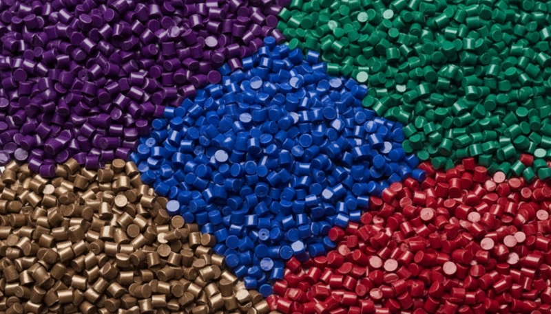
Сушите гранулы сырья в сушилке с осушающим бункером при температуре, специфичной для материала (80–160 °C), на протяжении 2–6 часов до снижения влажности ниже 0,02%, затем подавайте их непосредственно в бункер машины через герметичную линию передачи с сухим воздухом. Герметичные пакеты хранятся на складах, и гигроскопичные материалы быстро поглощают влажность после открытия — PA6 при относительной влажности 50% достигает влажности 0,3% за несколько часов, что значительно выше предела 0,02%. Сушка не является опциональной для инженерных пластиков; это первый контроль качества.
Drying specifications depend on material type. PA6 requires 80-100°C for 4-6 hours. PC needs 120°C for 3-4 hours. PEEK demands 150-160°C for 4-6 hours. Monitor dew point of the drying air—below -30°C indicates properly functioning equipment. Above -10°C means your dryer needs service.
Наш завод в Шанхае работает на 47 машинах для литья под давлением от 90T до 1850T, и у нас есть 6 специализированных станций сушки. С более чем 120 производственными работниками и 8 инженерами по пресс-формам мы видели, что происходит при спешке с сушкой материала. Мы поддерживаем осушители с точкой росы -40°C для гигроскопичных материалов и документируем параметры сушки для каждого из более чем 400 материалов, которые мы обрабатываем.
| Материал | Drying Temp (°C) | Drying Time (hrs) | Target Moisture (%) |
|---|---|---|---|
| PA6 | 80-100 | 4-6 | <0.02 |
| ПК | 120 | 3-4 | <0.02 |
| PEEK | 150-160 | 4-6 | <0.01 |
| ABS | 80-85 | 2-3 | <0.02 |
| POM | 80 | 2-3 | <0.02 |
Non-hygroscopic materials like polypropylene and PE do not require aggressive drying, but surface moisture from condensation should still be removed with a brief 1-2 hour drying cycle at 60-80°C. Skip drying entirely only if the material has been stored in a climate-controlled environment.
Проверка содержания влаги предотвращает поверхностные дефекты и структурную слабость в литых деталях. Используйте галогенный анализатор влаги или титрование по Карлу Фишеру, чтобы убедиться, что содержание влаги в смоле остаётся ниже порогового значения, специфичного для материала, перед загрузкой в бункер. Общие целевые показатели включают ПА6 и ПА66 ниже 0.2% влаги, поликарбонат и ПЭТФ при 0.02% или ниже, и ПБТ ниже 0.05%. На нашем заводе в Шанхае мы проверяем уровень влаги в каждой производственной партии перед началом обработки. Регранулят — даже при правильном хранении в герметичных контейнерах — поглощает окружающую влагу быстрее, чем первичная смола, что делает проверку особенно критичной при использовании смесей с регранулятом. Пропуск этой проверки приводит к серебристости, снижению ударной прочности и размерной нестабильности, которые никакая последующая корректировка параметров литья не может исправить.
Step 3: How Does Clamping and Mold Closing Work?
Смыкание прикладывает гидравлическое или механическое усилие, измеряемое в тоннах, для герметизации линии разъема формы против давления впрыска 18 000–50 000 фунтов на квадратный дюйм. Практическое правило простое: рассчитайте площадь проекции полости, умножьте на пиковое давление впрыска1, затем добавьте запаса безопасности 10–20%. Правильное замыкание предотвращает облой, защищает геометрию линии разъема и обеспечивает повторяемость размеров на протяжении производственных циклов.
Номинальная мощность машины определяет максимальную clamp force2 доступно. Работа пресс-формы на 60–80% от номинальной мощности обеспечивает оптимальную энергоэффективность при сохранении достаточного запаса безопасности для скачков давления на этапах впрыска и подпрессовки.
“Clamp force calculation requires 20-30% safety margin.”Правда
The formula (projected area × injection pressure) gives the theoretical minimum. Adding 20-30% compensates for pressure spikes during filling, thermal expansion of the mold, and variations in material viscosity.
“Higher clamp force always improves part quality.”Ложь
Excessive clamp force can crush venting channels, trap air causing burn marks, and accelerate mold wear. The goal is sufficient force to keep the mold closed without creating stress concentrations.
Mold closing speed follows a two-stage profile. Approach stage: rapid closing from 200-300 mm/s until the mold faces are within 5-10mm of contact. Positioning stage: slow closing from 5-10 mm/s for final closure to protect mold surfaces and alignment features. Some modern machines add a third low-pressure protection stage at 1-2 mm/s with 5-10 bar clamping pressure before full clamp engagement. This prevents damage if foreign material or a stuck part remains in the mold cavity.
Каждый начало смены
Step 4: How Does Plastic Melting and Injection Work?
Впрыск расплавляет гранулы смолы в нагретом цилиндре с помощью вращающегося шнека, затем подает гомогенизированный расплав в полость формы со скоростью 50–200 мм/с. Гранулы поступают в загрузочный бункер, проходят через нагретый цилиндр и подвергаются сдвигу вращающимся шнеком. Зоны питания, сжатия и дозирования транспортируют, расплавляют, гомогенизируют и дозируют материал, чтобы вязкость оставалась стабильной во время заполнения.
Screw rotation speed affects melt quality and throughput. Too slow: insufficient shear heating creates unmelted pellets. Too fast: excessive shear degrades the polymer and causes discoloration. Most engineering resins perform best at 50-120 RPM, with the speed adjusted based on screw diameter and material viscosity.
In our 20+ years of molding experience since 2005, we have accumulated extensive processing knowledge across 400+ materials. Our Shanghai factory maintains standard screw profiles for each material class and customizes for specialty grades. The screw recovery time—the time to accumulate enough melt for one shot—typically runs 2-4 seconds on our machines, contributing 10-15% to total продолжительность цикла3.
Injection begins when the screw stops rotating and moves forward as a plunger, forcing the accumulated melt through the nozzle, sprue, runner system, and into the cavity. Injection speed controls surface finish and weld line strength. Fast fill reduces temperature loss but can trap air. Slow fill improves venting but may cause premature freeze-off.
Step 5: What Is Packing and Holding Pressure?
The mold is 95-98% full. The cavity is mostly filled but not packed. Packing pressure compensates for volumetric shrinkage as the plastic cools from melt temperature to ejection temperature—typically 10-15% volumetric shrinkage for semi-crystalline materials. Without adequate packing, parts show sink marks, voids, and dimensional variation that pushes them out of tolerance.
“Packing pressure compensates for thermal shrinkage.”Правда
As plastic cools from injection temperature (200-300°C) to room temperature, density increases and volume decreases by 1-3% depending on material. Packing pressure pushes material into the cavity during this transition to maintain dimensional accuracy.
“Higher packing pressure always eliminates sink marks.”Ложь
Excessive packing causes flash at the parting line and ejection problems. Sink marks caused by thick wall sections require design changes like core-outs or rib redesign, not just pressure adjustments.
The critical decision point is gate freeze-off time. The gate must solidify before holding pressure is released, or material flows back out of the cavity. Typical gate freeze times range from 1-3 seconds for edge gates to 0.3-0.8 seconds for sub-gates. Monitor cavity pressure curves—a sharp pressure drop after packing indicates premature gate unfreeze.
Packing pressure profile can be staged rather than constant. Stage 1: High pressure (80-100% of injection) for 20-30% of packing time to drive material into thick sections and corners. Stage 2: Reduced pressure (50-70% of injection) for the remaining time to maintain density without over-packing. This profile reduces sink marks while minimizing flash risk. The transition point is determined by observing the part weight curve and visual inspection of thick sections for sink marks under different pressure levels.
Step 6: How Does Cooling and Solidification Work?
The gate is frozen. The material is packed. The part is dimensionally stable enough to survive ejection but needs to solidify fully before the mold opens. Cooling time dominates cycle time at 60-80% of the total. A 10-second reduction in cooling time on a 25-second cycle is a 40% productivity gain. This is where engineering pays for itself.
Традиционное охлаждение использует прямые каналы диаметром 8–12 мм с шагом в 3–5 раз больше диаметра и расстоянием от поверхности детали до центральной линии канала в 2–3 диаметра. Это работает для деталей с равномерной толщиной стенки и простой геометрией. При наличии бобышек, ребер или переменной толщины стенки равномерное охлаждение становится проблематичным — толстые участки охлаждаются медленнее, вызывая дифференциальную усадку, коробление и остаточные напряжения.
ZetarMold has implemented conformal cooling channels on high-volume molds since 2013. By following the mold cavity contour rather than straight drilling, we have reduced cooling time by 20-35% for complex parts. This capability, combined with our in-house mold manufacturing facility, allows us to deliver 100+ molds per month with optimized cooling designs.
| Материал | 2mm Wall (s) | 3mm Wall (s) | 4mm Wall (s) |
|---|---|---|---|
| PP | 8-10 | 12-15 | 16-20 |
| ABS | 10-12 | 15-18 | 20-24 |
| ПК | 12-15 | 18-22 | 25-30 |
| PA6 | 10-12 | 15-18 | 20-25 |
| PEEK | 15-18 | 22-27 | 30-36 |
Coolant temperature should be 10-20°C below the material’s heat deflection temperature. For PC, set mold temperature at 80-100°C. For PP, 20-40°C works. Higher mold temperatures improve surface finish and crystallinity but extend cycle time. The tradeoff is always cosmetic quality versus throughput.
Оптимизация охлаждения может сократить время цикла на 20–35% на существующих пресс-формах без изменений оборудования. Корректировки процесса: сократите время подпрессовки до минимума, сохраняющего вес детали, увеличьте скорость потока охлаждающей жидкости в пределах возможностей насоса, снизите температуру пресс-формы до минимума, предотвращающего деформацию. Модификации пресс-формы: добавьте перегородки для охлаждения глубоких сердечников, переместите каналы ближе к толстым участкам, установите конформное охлаждение для сложных геометрий. ROI обычно достигается в пределах 1000–5000 деталей.
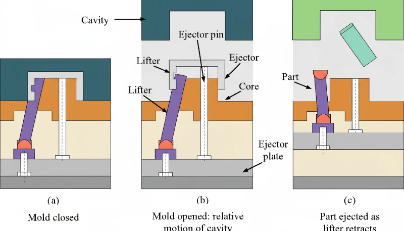
Step 7: How Does Mold Opening and Part Ejection Work?
The part is solidified. The cooling time has elapsed. The mold opens. This seems straightforward, but ejection is where 20-30% of injection molding defects occur. Ejection requires overcoming two forces: adhesion of the cooled plastic to the mold steel and mechanical interlocking due to undercuts or insufficient draft. The ejection system must apply enough force to overcome these factors without distorting the part, creating ejector pin marks, or causing part stick-back on the core side.
“Ejection force should be 1.5-2 times the projected part area.”Правда
Для площади проекции детали 50 см² на поверхности формы усилие выталкивания 75–100 Н обеспечивает надежное извлечение при минимальных следах от толкателей. Чрезмерное выталкивание вызывает следы от толкателей и повреждение поверхности.
“More ejector pins always improve ejection reliability.”Ложь
Excessive pins create surface marks, increase mold cost, and create more failure points. Strategic pin placement at rib intersections and corners is more effective than pin quantity alone.
Ejection system selection depends on part geometry. Straight ejection uses ejector pins for simple geometries. Sleeve ejection handles bosses and cylindrical features. Stripper plate ejection works best for thin-wall cups and caps. For undercuts, you need lifters or angled pins. Choosing the wrong system causes part deformation, sticking, or tooling damage that compounds over thousands of cycles.
Ejector pin placement follows specific guidelines. Place pins in thick sections and rib intersections where ejection resistance is highest. Space pins evenly along the part perimeter to distribute force. Pin diameter should be at least 1.5x the pin length to prevent bending. For polished or textured surfaces, avoid placing pins on visible cosmetic areas.
Mold opening speed affects ejection quality. The opening profile: slow initial opening (5-10 mm/s) for first 10-20mm to allow part separation from core without stress. Rapid opening (100-200 mm/s) for the majority of the stroke to minimize cycle time. Deceleration (20-50 mm/s) for final 50-100mm to avoid slamming the mold open and reducing wear on guide pins and bushings. The deceleration is particularly important for molds with stripper plates or complex lifters that need controlled opening sequences.
Step 8: How Do You Inspect Quality and Monitor the Process?
The part is ejected. It lands in the chute or is robotically removed. Now what? If you assume the process is set and let it run, you will discover defects hours or days later when your customer rejects the shipment. Quality inspection must happen at every shift start, after every material change, and at defined intervals during production. The inspection hierarchy: first article inspection (FAI) on startup, in-process inspection every 50-100 parts, final inspection on each shipment lot.
At ZetarMold, our quality workflow covers IQC (incoming quality control), in-process checks with samples, process inspection, packaging inspection, FQC (final quality control), and OQC (outgoing quality control). We have 10+ QC specialists who verify dimensions, surface quality, and functional requirements on every production run. This 6-step workflow, combined with ISO 9001/13485/14001/45001 certifications, ensures consistent quality across our Shanghai factory operations.
Visual inspection catches 60-70% of defects. Burn marks, flash, short shots, sink marks, and surface blemishes are immediately visible. Train operators to inspect critical cosmetic zones first, then structural features. Use backlit inspection stations for transparent parts and polarized light for birefringence detection in optical components.
| Check | Method | Frequency | Acceptance Criteria |
|---|---|---|---|
| Visual Defects | Lightbox inspection | Every 50 parts | No sink >0.2mm in A-surface |
| Dimensions | CMM/caliper | Every 100 parts | ±0.1mm for ±0.05mm tolerance |
| Вес | Scale | Every 25 parts | ±2% of target weight |
| Fit/Function | Assembly test | Every shift start | Для расчета усилия смыкания сначала определите проекционную площадь детали на линии разъема формы. Для прямоугольной детали это длина, умноженная на ширину, в квадратных дюймах. Умножьте эту площадь на давление впрыска в psi, чтобы получить усилие разъема в фунтах, затем переведите в тонны (разделите на 2 000). Наконец, добавьте коэффициент безопасности 20-30%. Например: деталь с проекционной площадью 10 квадратных дюймов, отлитая под давлением 18 000 psi, создает усилие разъема 180 000 фунтов, что равно 90 тоннам. С запасом безопасности 25% следует выбрать машину с усилием смыкания не менее 112-115 тонн. |
| Cosmetic | Golden sample | Every part | Match appearance reference |
Dimensional inspection verifies parts meet print requirements. Critical dimensions use CMM (coordinate measuring machine) measurement with ±0.01mm accuracy. Standard dimensions get caliper or go/no-go gauge checks. Sample 5 parts per 100-shot cycle for statistical process control, tracking Cp and Cpk values.
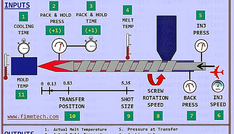
Современные машины отслеживают давление впрыска, давление подпрессовки, температуру расплава, температуру формы, время цикла и время восстановления шнека в реальном времени. Сигналы тревоги при отклонении ±10–20% от целевых значений запускают автоматические паузы, изолируют затронутые детали и оповещают операторов — выявляя дрейф процесса до накопления несоответствующих деталей.
What Are Common Injection Molding Issues and How Do You Troubleshoot Them?
Распространенные дефекты литья под давлением — утяжины, облой и недоливы — возникают даже в хорошо настроенных процессах. Вот основные причины и способы устранения.
Sink marks occur when thick sections cool slower than adjacent thin sections, creating surface depressions. The root cause is differential shrinkage. Troubleshooting path: first check wall thickness ratio—if it exceeds 3:1, redesign is required. If wall thickness is acceptable, increase packing pressure in 10% increments while monitoring for flash. Add baffles or bubblers to cool thick sections faster. Reduce melt temperature 5-10°C to minimize initial shrinkage. In severe cases, add external core-outs or gas-assisted molding to eliminate thick sections entirely.
Flash appears at the parting line, around ejector pins, or in vent gaps when material escapes the cavity under excessive injection or packing pressure. Contributing factors include worn mold surfaces, insufficient clamp force, and high melt temperatures that reduce viscosity. Fix flash by increasing clamp force first, then reducing packing pressure, and finally checking mold surface alignment if the problem persists across multiple cavities.
Short shots occur when the cavity is not completely filled, leaving incomplete parts. Common causes include insufficient injection pressure, blocked vents preventing air escape, low melt temperature increasing viscosity, or inadequate shot size. Diagnose by checking injection pressure curves first—most short shots resolve by raising injection speed or pressure by 10-15%. If venting is the issue, clean or deepen vent channels to 0.01-0.02mm depth.
When Should You Adjust vs. Redesign Your Injection Molding Process?
Переходите к перепроектированию, если три или более изменений параметров на ±20% не дают результата, или если коренные причины включают соотношение толщин стенок более 3:1 или недостаточные углы уклона. Эмпирическое правило: если вы скорректировали три параметра на ±20%, а дефект сохраняется, проблема, вероятно, связана с конструкцией. Продолжение корректировок после этого приводит к потере материала и времени цикла без решения проблемы.
“Wall thickness ratio >3:1 requires design modification.”Правда
When wall thickness exceeds 3:1 ratio, process adjustments cannot eliminate sink marks and warpage. Core-outs, rib redesign, or gas-assisted molding are necessary design solutions.
“All short shots require mold redesign.”Ложь
Short shots caused by venting issues, material contamination, or improper drying can be fixed through process changes. Only short shots caused by flow length limitations or trapped air in geometry require mold modification.
Design issues that resist process adjustment fall into five categories: wall thickness non-uniformity (causes sink and warp), inadequate draft angles (causes sticking), incorrect gate type or location (causes flow lines and weld lines), insufficient coring (wastes material and cycle time), and sharp corners without fillets (creates stress concentrators). Each of these requires a mold modification, not a parameter tweak.
Перепроектирование стоит 5000–15 000 долларов США на инжиниринг, модификацию и повторную валидацию, но производство бракованных деталей при уровне брака 5–15% на партии в 100 000 штук обходится гораздо дороже.
How Do You Optimize Injection Molding for Production Efficiency?
Сначала оптимизируйте охлаждение — оно занимает 60–80% каждого цикла — с помощью конформных каналов и турбулентного потока, затем минимизируйте время дожатия и выталкивания. Время цикла складывается из времени впрыска (5–10%), времени дожатия и выдержки (10–20%), времени охлаждения (60–80%), времени открытия и закрытия формы (5–10%) и времени выталкивания (2–5%). Охлаждение является доминирующим фактором, поэтому оптимизацию следует начинать с него, а затем переходить к другим компонентам.
ZetarMold работает на 47 машинах для литья под давлением от 90T до 1850T, и в прошлом году мы оптимизировали охлаждение более чем на 100 пресс-формах. Реализация конформного охлаждения, оптимизация потока охлаждающей жидкости и переработка системы впуска позволили сократить время цикла на 15–30% на нескольких производственных линиях. Эти улучшения, вместе с более чем 20-летним опытом работы с 2005 года, позволяют нам предлагать конкурентные цены при сохранении качества.
Cooling optimization targets three areas: channel placement, coolant parameters, and mold material selection. Conformal cooling channels follow the part contour, reducing distance to the cavity surface from 15-25mm (drilled) to 3-8mm (conformal). Coolant flow rate must maintain turbulent flow (Reynolds number above 5,000) for effective heat transfer. Mold materials with higher thermal conductivity like beryllium copper inserts in hot spots can cut local cooling time by 30-40%.
Injection optimization focuses on fill time and melt quality. Fill time optimization: reduce injection time until you see burn marks (too fast) or short shots (too slow), then back off 10%. Velocity-to-pressure switchover point should trigger at 95-98% fill to avoid overshooting. Melt temperature profiling across barrel zones prevents degradation while ensuring complete melting.
| Компонент | Typical % of Cycle | Optimization Potential | ROI Timeline |
|---|---|---|---|
| Охлаждение | 60-80% | 15-30% | 500-2000 parts |
| Packing/Holding | 10-20% | 10-20% | Immediate |
| Mold Open/Close | 5-10% | 5-15% | Immediate |
| Инъекция | 5-10% | 5-10% | 100-500 parts |
| Выброс | 2-5% | 5-10% | 1000-5000 parts |
ROI зависит от стоимости детали и объема. Окупаемость менее 1000 деталей должна быть реализована немедленно; 1000–5000 деталей требуют оценки; свыше 5000 деталей необходимо стратегическое обоснование.
Часто задаваемые вопросы о процессе литья под давлением
Часто задаваемые вопросы
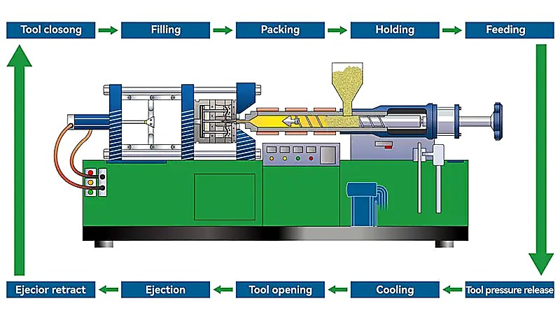
What are the 7 steps of injection molding?
The seven steps of injection molding are: (1) clamping and mold closing, where the machine secures the two mold halves together under high pressure; (2) plastic melting and injection, where heated pellets become molten and are forced into the cavity; (3) packing and holding, where additional material compensates for shrinkage; (4) cooling and solidification, where the part hardens inside the mold; (5) mold opening and part ejection, where the finished part is removed; (6) quality inspection, which covers visual, dimensional, and functional checks; and (7) process monitoring and adjustment, ensuring consistent output throughout production runs.
How long does an injection molding cycle take?
Cycle time ranges from as short as 5 seconds for small thin-wall parts to over 120 seconds for large, thick-wall components. For a typical engineering plastic part with 3mm wall thickness, expect 15-25 seconds per cycle. Cooling dominates the timeline, accounting for 60-80% of total cycle time, while injection fills the cavity in just 0.5-2 seconds. Reducing cooling time through conformal channels or optimized coolant flow is the single most effective way to increase throughput, often cutting cycle time by 20-35% on existing molds.
What is the difference between injection and packing?
Injection is the high-pressure fill phase where molten plastic is forced into the mold cavity at speeds designed to fill 95-98% of the volume, typically completing in 0.5-2 seconds. Packing (or holding) follows immediately at lower pressure, pushing additional material into the cavity to compensate for thermal shrinkage as the plastic cools and contracts. Packing continues until the gate freezes off, usually 2-6 seconds. Think of injection as getting the material into the mold, and packing as keeping it dimensionally accurate as it solidifies.
Why do I need to dry plastic before injection molding?
Hygroscopic materials such as PA6, PC, PET, and PEEK absorb moisture from ambient air over time. During injection molding, this trapped moisture vaporizes instantly at melt temperatures (often above 250°C), causing visible bubbles (splay marks), surface streaks, reduced mechanical strength, and dimensional instability in the finished part. Proper drying at material-specific temperatures (80-160°C) for 3-6 hours reduces moisture content below the critical 0.02% threshold required for defect-free molding. Skipping the drying step remains one of the most common and costly causes of rejected parts in production.
What temperature is used for injection molding?
Injection molding temperatures vary significantly by material type. Polypropylene processes at 180-220°C, ABS at 210-250°C, polycarbonate at 280-320°C, and high-performance PEEK requires 380-420°C. The barrel maintains a temperature gradient from the feed zone (coolest) through compression to the metering zone (hottest), typically with a 20-40°C rise. Mold temperature also plays a critical role: colder molds speed up cycle time but can increase residual stress, while heated molds (60-150°C depending on resin) improve surface finish, crystallinity, and dimensional stability for engineering-grade materials.
How much pressure is needed for injection molding?
Injection pressure typically ranges from 18,000 to 25,000 psi for standard engineering thermoplastics. High-viscosity or glass-filled materials like PEEK or PA66-GF30 can require up to 35,000-50,000 psi. Packing pressure runs at 50-80% of injection pressure. To determine required clamp force, multiply the projected part area (in square inches) by injection pressure, then add a 20-30% safety margin. For example, a 10 square inch part at 18,000 psi needs roughly 90 tons of clamp force, so a 110-115 ton machine provides adequate headroom.
What causes sink marks in injection molding?
Sink marks form when thick wall sections cool more slowly than adjacent thin sections, creating differential shrinkage that physically pulls the surface material inward. The primary causes include wall thickness ratios exceeding 3:1, insufficient packing pressure or hold time, and inadequate cooling channel placement near heavy cross-sections. Practical fixes include coring out thick sections during the DFM stage, increasing packing pressure and extending hold time until gate freeze, and redesigning cooling channels to target thick areas. Process adjustments can resolve mild cases, but severe recurring sinks usually require a mold modification.
How do you calculate clamp force for injection molding?
To calculate clamp force, first determine the projected area of the part at the mold parting line. For a rectangular part, this is length times width in square inches. Multiply that area by the injection pressure in psi to get the separating force in pounds, then convert to tons (divide by 2,000). Finally, add a 20-30% safety factor. For example: a part with 10 square inches of projected area molded at 18,000 psi produces 180,000 pounds of separating force, which equals 90 tons. With a 25% safety margin, you would select a machine with at least 112-115 tons of clamp capacity.
-
давление впрыска: Давление впрыска — это гидравлическое давление, прикладываемое к шнеку для подачи расплавленного пластика в полость формы, обычно в диапазоне от 35 000 до 50 000 фунтов на квадратный дюйм. ↩
-
clamp force: Усилие смыкания — это гидравлическое или механическое усилие, удерживающее форму закрытой во время впрыска, измеряется в тоннах, обычный диапазон составляет от 90 до 1850 тонн. ↩
-
продолжительность цикла: Время цикла — это общая продолжительность, необходимая для завершения одного цикла литья под давлением, измеряется в секундах, от закрытия формы до начала следующего цикла. ↩


