 Перейти к содержанию

Вы только что получили первые производственные образцы, и детали застревают в форме. Толкатели оставляют следы. На некоторых деталях даже есть задиры по боковой поверхности. Ваш инструментальщик говорит, что нужно увеличить угол уклона. Вы запрашивали нулевой уклон, потому что CAD-модель выглядела чистой. Теперь у вас есть форма $12,000, требующая доработки. Хорошая новость: эту проблему проще всего предотвратить, если разобраться в углах уклона до начала изготовления оснастки.
Эта статья охватывает то, что угол осадки1 — это, почему это важно, стандартные значения по материалам и текстурам, а также ошибки, которые, как я видел, стоили реальных денег на реальных производственных циклах.
- Стандартная конусность для большинства полированных поверхностей составляет от 1 до 2 градусов на сторону.
- Для текстурированных поверхностей требуется дополнительно от 1 до 1,5 градусов конусности на каждый класс текстуры.
- Нулевой уклон возможен, но рискован и почти никогда не оправдан в серийном производстве.
- Уклон должен быть задан до начала изготовления оснастки — доработка обходится дорого.
- Усадка, материал и толщина стенок влияют на минимальный необходимый угол уклона.
Правильный расчет угла уклона обеспечивает стабильность
A литьё под давлением угол уклона — это преднамеренная конусность, создаваемая на каждой вертикальной поверхности полости формы. Представьте его как небольшой наклон, который вы добавляете к стенке, чтобы деталь могла свободно выскользнуть после охлаждения и усадки на сердечник. Без него деталь сцепляется со сталью, как вакуумная прокладка, и извлечение превращается в борьбу между толкателями и поверхностью формы.
Угол конусности измеряется в градусах от вертикальной оси направления раскрытия формы. Конусность в 1 градус означает, что стенка отклоняется наружу примерно на 0,0175 мм на каждый мм глубины. На кармане глубиной 50 мм это даёт около 0,87 мм зазора с каждой стороны вверху. Это кажется небольшим, но это разница между чистым извлечением и застрявшей деталью.
Каждая вертикальная поверхность вашей детали требует уклона. Это включает внешние стенки, внутренние ребра жёсткости, бобышки, карманы и даже сквозные отверстия. Если поверхность параллельна направлению раскрытия формы и не имеет конусности, деталь будет застревать при извлечении, оставляя царапины, задиры или деформации.

Почему угол конусности важен для качества детали?
В этом разделе речь идёт о том, почему угол конусности важен для качества детали и как он влияет на стоимость, качество, сроки или риски снабжения. Угол конусности напрямую влияет на четыре аспекта: внешний вид детали, точность размеров, срок службы инструмента и время цикла. Когда деталь застревает в форме, литьевая форма система выброса2 должна работать интенсивнее. Толкатели оставляют следы. На поверхности детали появляются линии волочения. В худшем случае деталь трескается или деформируется до извлечения.
Недостаточный уклон также ускоряет износ формы. При каждом цикле деталь царапает стенку полости при извлечении. За 100 000 циклов постоянное трение полирует и повреждает стальную поверхность. Форма, рассчитанная на 500 000 циклов, может потребовать полировки или доработки уже на 200 000.
На стороне производства детали, которые трудно извлечь, замедляют цикл. Если ваш оператор должен вручную выбивать деталь или если робот с трудом её захватывает, вы теряете секунды на каждом цикле. В масштабе это складывается в реальные деньги. Задержка в 3 секунды на 30-секундном цикле означает потерю 10 процентов мощности.
“A 1-degree draft angle can reduce ejection force by up to 50% compared to zero draft.”Правда
Конусность нарушает эффект вакуума между сжимающимся пластиком и сердечником формы. Даже небольшой угол значительно снижает коэффициент трения при извлечении, уменьшая усилие, необходимое для системы выталкивания.
“If the mold has enough ejector pins, you do not need draft angle.”Ложь
Большее количество толкателей лучше распределяет усилие, но они не могут преодолеть фундаментальное трение между параллельной стенкой и сжимающимся пластиком. Без уклона толкатели просто концентрируют усилие на меньших площадях, увеличивая риск следов от толкателей и деформации детали.
Каковы стандартные значения угла уклона?
Не существует единственно правильного угла уклона — он зависит от материала, качества поверхности, глубины и требований к допускам. Но вот значения, которые работают на практике в тысячах производственных форм.
| Отделка поверхности | Минимальный уклон | Recommended Draft | Примечания |
|---|---|---|---|
| Polished (SPI A-1 to A-3) | 0.5° | 1° | Гладкая поверхность легко отделяется |
| Стандартная (SPI B-1 до B-3) | 1° | 1.5° | Лёгкие следы механической обработки |
| Мелкая текстура (VDI 12-24) | 1° | от 1,5° до 2° | Добавьте 1° на каждый класс глубины текстуры |
| Средняя текстура (VDI 27-33) | 1.5° | 2° до 3° | Текстура фиксируется на поверхности детали |
| Сильная текстура (VDI 36-45) | 2° | 3° до 5° | Глубокая текстура действует как микро-поднутрения |
| Полированная поверхность, нулевой уклон | 0° | Not recommended | Только для неглубоких элементов менее 10 мм |
Эмпирическое правило, которым я пользуюсь: начинайте с 1 градуса на сторону для полированных поверхностей, добавляйте 1 градус на каждое увеличение класса текстуры и никогда не опускайтесь ниже 0,5 градусов для чего-либо глубже 10 мм. Если ваш клиент возражает против конусности из-за ограничений по размерам, покажите ему расчёты стоимости переделки по сравнению с конусностью в 0,5 градуса.
Для внутренних элементов, таких как ребра жёсткости и бобышки, ситуация с уклоном более критична. Пластик при охлаждении сжимается на сердечнике, создавая плотное сцепление. Для ребер жёсткости минимальный уклон должен составлять не менее 0,5 градуса с каждой стороны, но безопаснее использовать 1 градус. Бобышки требуют минимум 0,5 градуса снаружи, а внутреннее отверстие также должно иметь уклон, если оно формируется стержнем.
Как усадка материала влияет на требования к конусности?
усадка3 — это основная причина, по которой вообще существует конусность. Когда пластик остывает в форме, он усаживается. Если деталь имеет форму чашки или коробки, эта усадка плотно прижимает стенки к сердечнику формы. Чем выше степень усадки, тем сильнее сцепление и тем больше конусности требуется.
| Материал | Скорость усадки | Min Draft (Polished) | Минимальный уклон (текстурированный) |
|---|---|---|---|
| ABS | 0.4–0.7% | 0.5° | 1.5° |
| Поликарбонат (PC) | 0.5–0.7% | 0.5° | 1.5° |
| Полиамид 6 (ПА6) | 0.5–1.5% | 1° | 2° |
| Полиамид 66 (ПА66) | 0.8–2.0% | 1° | 2.5° |
| Glass-Filled Nylon | 0.2–0.8% | 0.5° | 1.5° |
| PP (полипропилен) | 1.0–2.5% | 1° | 2.5° |
| ПЭ (полиэтилен) | 1.5–3.0% | 1.5° | 3° |
| POM (Acetal) | 1.5–2.5% | 1° | 2.5° |
| PBT | 0.8–2.0% | 1° | 2° |
Кристаллические материалы, такие как нейлон, ПП и ПОМ, сжимаются больше, чем аморфные материалы, такие как ABS и ПК. Это означает, что они сильнее держат сердечник и требуют больше уклона. Нейлон с стекловолокном является исключением: стекловолокно уменьшает усадку, поэтому он фактически требует меньше уклона, чем нейлон без наполнителя, даже если волокна делают материал более абразивным для формы.
У нас был проект корпуса из PP, где клиент требовал уклона 0,5 градуса с средней текстурой. Детали застревали на каждом втором цикле. Мы перерезали сердечник, добавив ещё 1,5 градуса уклона — три недели потерянного производства. PP с усадкой 2,5 процента на текстурированной поверхности никогда бы не работал при уклоне 0,5 градуса.
Что происходит, когда конусности недостаточно?
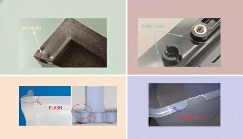
Симптомы проявляются сразу на производственном участке. Вот что вы увидите, в порядке возрастания серьезности:
Во-первых, следы волочения. Поверхность изделия получает параллельные царапины вдоль направления выталкивания. На полированных изделиях это сразу заметно и бракует изделие по косметическому виду. На текстурированных изделиях текстура полируется полосами, создавая неравномерную отделку, которую никакая последующая обработка не исправит.
Во-вторых, следы от толкателей. Когда изделие сопротивляется выталкиванию, толкатели концентрируют усилие на небольших участках. На внутренней стороне появляются белые следы напряжения, видимые следы от толкателей или даже сквозные отверстия от толкателей, если стенка тонкая. В нашей мастерской мы считаем любой след от толкателя глубже 0,1 мм браком для видимых поверхностей.
В-третьих, искажение изделия. Если изделие все же высвобождается, но с большим усилием выталкивания, оно может покоробиться, прогнуться или треснуть. Тонкостенные изделия особенно уязвимы. Усилие, необходимое для выталкивания изделия с нулевым уклоном из глубокой полости, может превысить структурную прочность стенки, вызывая необратимую деформацию.
Четвертая — повреждение формы. Со временем постоянное выталкивание с высокой силой приводит к износу отверстий толкателей, повреждению поверхностей полости и может вызвать трещины в сердечниках. Форма с глубокими полостями без уклона может требовать замены толкателей каждые 50 000 циклов вместо каждых 200 000. Это в четыре раза больше затрат на обслуживание.
«Добавление 1 градуса уклона на текстурированную поверхность может полностью устранить следы волочения при выталкивании.»Правда
Дополнительный уклон создаёт зазор между усаживающимся пластиком и текстурированной стальной поверхностью. Этот зазор разрушает механическое сцепление между текстурированным рисунком и затвердевшей поверхностью детали, обеспечивая чистое отделение.
«Угол уклона важен только для косметических деталей — конструкционные детали не нуждаются в нем.»Ложь
Уклон — это механическое требование, не только косметическое. Конструкционные детали испытывают те же силы усадки и трения при выталкивании. Фактически, конструкционные детали с жесткими допусками даже более чувствительны к деформации при выталкивании, вызванной недостаточным уклоном.
Как текстура и чистота поверхности влияют на требования к углам уклона?
Здесь возникает большинство проблем с уклоном. Полированная поверхность формы по сути гладкая — изделие выходит с минимальным трением. Но текстурированная поверхность имеет микроскопические пики и впадины, которые действуют как крошечные поднутрения. По мере усадки пластик обхватывает эти пики, создавая механическую блокировку, препятствующую выталкиванию.
Промышленный стандарт: добавляйте 1 градус уклона на каждые 0,01 мм глубины текстуры. Большинство поставщиков текстуры оценивают свои паттерны по шкале от мелкой до грубой. Мелкая текстура пескоструйной обработки может иметь глубину 0,01 мм и требовать всего 1 дополнительный градус. Глубокий кожанный рисунок может иметь глубину 0,05 мм и требовать 5 дополнительных градусов сверх базового уклона.
Если вы указываете текстуру на детали, всегда сообщайте изготовителю инструмента до изготовления формы. Изменение поверхности после изготовления инструмента часто означает перерезку полости для добавления уклона, что дорого и может повлиять на размеры детали. У нас был случай, когда клиент добавил текстуру VDI-33 к форме, которая была разработана для полированной поверхности с уклоном 1 градус. Форму нужно было вынуть, полость перерезать до уклона 3,5 градуса и повторно полировать. Шесть недель простоев.
Как рассчитать угол уклона для вашей детали?
Базовый расчет прост. Зазор от уклона равен тангенсу угла уклона, умноженному на глубину элемента:
Зазор на сторону = tan(угол уклона) × глубина
Например, уклон 1 градус на стенке глубиной 50 мм дает: tan(1°) x 50 = 0,0175 x 50 = 0,87 мм зазора на сторону. При 2 градусах это 1,75 мм на сторону. При 3 градусах — 2,62 мм на сторону.
Практический вопрос не в математике — он в том, может ли ваша деталь допускать такое большое изменение размера от основания к вершине. Для большинства корпусов и оболочек уклон от 1 до 2 мм на стенке толщиной 50 мм не заметен конечному пользователю. Но для точных компонентов, таких как шестерни, места посадки подшипников или сопрягаемые поверхности, вам может потребоваться более жесткий уклон или альтернативные стратегии выталкивания.
| Глубина (мм) | Уклон 0.5° | 1° Уклон | Уклон 1.5° | Уклон 2° | Уклон 3° |
|---|---|---|---|---|---|
| 10 | 0.09 | 0.17 | 0.26 | 0.35 | 0.52 |
| 25 | 0.22 | 0.44 | 0.65 | 0.87 | 1.31 |
| 50 | 0.44 | 0.87 | 1.31 | 1.75 | 2.62 |
| 75 | 0.65 | 1.31 | 1.96 | 2.62 | 3.93 |
| 100 | 0.87 | 1.75 | 2.62 | 3.49 | 5.24 |
Заметьте, что даже небольшая глубина 10 мм с углом 0,5 градуса дает всего 0,09 мм зазора. Это почти недостаточно для преодоления поверхностного трения, особенно если есть текстура. Именно поэтому большинство производителей инструментов сопротивляются любым значениям ниже 1 градуса — допустимая ошибка слишком мала.
What Are Common Draft Angle Mistakes?
Распространенные ошибки в угле уклона — это основные категории или варианты, объясненные в этом разделе. После 20 лет изготовления форм одни и те же ошибки возникают снова и снова. Вот те, которые стоят больше всего денег:
Ошибка 1: Применение уклона только к внешним стенкам. Внутренние элементы, такие как ребра, бобышки и подкосы, часто забывают. Эти поверхности сжимаются на сердечник так же, как и внешние стенки, но их труднее вытолкнуть, потому что толкатели не могут достичь их напрямую. Каждое ребро требует минимум 0,5 градуса с каждой стороны. Каждая бобышка требует минимум 0,5 градуса снаружи.
Ошибка 2: Направления уклона в противоположных сторонах. Если вы задаете уклон на стороне матрицы в одну сторону, а на стороне пуансона — в другую, изделие становится толще с одного конца и тоньше с другого. Это создает неравномерную толщину стенки, что приводит к короблению и утяжинам. Весь уклон на заданном элементе должен сходиться к плоскости разъема формы, чтобы толщина стенки оставалась постоянной.
Ошибка 3: Игнорирование уклона на поверхностях запирания. Когда сквозное отверстие или окно формируется обеими половинами формы, соприкасаясь, поверхности смыкания также требуют уклона. Без него область контактa металла с металлом действует как тормоз при открытии формы. Мы видели формы, где усилие пресса приходилось увеличивать на 20 процентов только для преодоления трения смыкания из-за горизонтальных поверхностей с нулевым уклоном.
Ошибка 4: Не учтена текстура после формования. Некоторые клиенты планируют добавить текстуру после формования с помощью окраски или тампопечати. Если угол уклона был рассчитан для полированной поверхности, а последующая обработка добавляет толщину, эффективный зазор уменьшается. Всегда проектируйте для конечного состояния поверхности, а не для состояния после формования.
Ошибка 5: Отсутствие уклона на глубоких полостях. Это самая дорогостоящая ошибка. Глубокие полости без уклона почти всегда вызывают проблемы с выталкиванием. Если в конструкции абсолютно нельзя иметь уклон, планируйте разъемный сердечник или складываемый сердечник с самого начала. Это дороже на начальном этапе, но избегает затрат на переработку позже.
Как работать с уклоном на сложных геометриях детали?
Не все детали представляют собой простые коробки с прямыми стенками. Реальные производственные детали имеют подрезы, боковые элементы, угловые отверстия и асимметричную геометрию. Вот как обращаться с уклоном в распространённых сложных случаях.
Наклонные поверхности. Если стенка уже имеет угол больше требуемого уклона, вам не нужно добавлять больше. Стена, отклоненная на 5 градусов от вертикали, уже имеет уклон 5 градусов. Добавляйте уклон только если поверхность ближе к вертикали, чем минимальное требование.
Рёбра и косынки. Задавайте уклон ребер от основания к вершине. Основание — самая толстая часть и место соединения ребра со стенкой. Вершина — самая тонкая. Типичное ребро имеет от 0,5 до 1 градуса с каждой стороны, что естественным образом делает вершину тоньше. Убедитесь, что вершина не становится тоньше 0,5 мм, иначе она не заполнится должным образом.
Винты и подрезы. External threads formed in the cavity need draft on the thread flanks, which changes the thread profile. This is why most production threaded parts use threaded inserts or unscrewing cores instead of direct molded threads. If you must mold threads, work with your toolmaker to validate the thread gauge will still fit after draft is applied.
Louver and vent patterns. These features have thin vanes that need draft on both sides. Because they are thin and deep, they are ejection trouble spots. Use a minimum of 1 degree per side, and specify polished surfaces on the mold for these features.
What Draft Angle Should You Specify in Your Mold Design?
Here is the decision framework I use when reviewing a mold design for draft adequacy. It works for 95 percent of production parts:
Step 1: Identify every surface that is parallel to the mold opening direction. Mark them in your CAD system with a color code. Red for zero draft, yellow for marginal draft (0.5 degrees or less), green for adequate draft (1 degree or more).
Step 2: For each red or yellow surface, determine the surface finish. Polished surfaces can get away with less draft. Textured surfaces need more. Check with your texture supplier for their recommended draft per pattern.
Step 3: Check the material shrinkage. Cross-reference the shrinkage rate with the draft table above. Higher shrinkage means you need more draft to overcome the grip on the core.
Step 4: Verify wall thickness is consistent from bottom to top. If adding draft makes the wall too thick or too thin at one end, adjust the part geometry to compensate. Moving the parting line or changing the wall profile are usually the easiest fixes.
Step 5: Review with your toolmaker before cutting steel. A 30-minute design review can save weeks of rework. Your toolmaker knows which features are ejection trouble spots from experience.
In our factory, our engineers review every mold design for draft adequacy before machining begins. Our team checks ribs, bosses, textured sidewalls, and ejection direction against the DFM record, so draft-related rework stays below 1% across 100+ mold sets delivered per month from our Shanghai factory.
That is why our team treats draft angle as a production-risk review item, not a cosmetic CAD preference. Our engineers mark any zero-draft or marginal-draft surface before steel cutting, then confirm the customer can accept the small taper before machining starts.
Часто задаваемые вопросы
What is the minimum draft angle for injection molding?
The minimum draft angle is 0.5 degrees per side for polished surfaces on low-shrinkage materials like ABS or PC. For textured surfaces or high-shrinkage materials like PP or nylon, the practical minimum is 1.5 to 2 degrees. Anything less than 0.5 degrees is extremely risky and should only be attempted on shallow features under 10 mm depth with polished mold surfaces and robust ejection systems. In production environments, most experienced toolmakers will not recommend going below 1 degree on any surface deeper than 15 mm regardless of finish or material.
Can you injection mold without draft angle?
Technically yes, but it is almost never recommended for production runs. Zero draft is possible on very shallow features under 10 mm with polished mold surfaces and low-shrinkage materials. For anything deeper, zero draft will cause ejection drag marks, pin push, part warpage, and accelerated mold wear that dramatically shortens tool life. If your design absolutely requires zero draft, plan for alternative ejection methods like air blasts, stripper plates, or collapsible cores from the start. These alternatives add cost and complexity but are necessary to avoid production problems.
How much draft do you need for textured injection molded parts?
The standard rule is 1 degree of draft per 0.01 mm of texture depth. A fine texture rated VDI 12 to 24 typically needs 1 to 1.5 degrees of additional draft on top of the base 1 degree. Medium textures need 2 to 3 degrees total per side. Heavy textures like leather grain may require 3 to 5 degrees total per side. Always confirm with your texture supplier, as their specific pattern depth determines the exact requirement. Failing to add sufficient draft for texture is one of the most common and expensive mold design mistakes in the industry.
Does draft angle affect part tolerances?
Yes, draft angle changes the part dimensions from bottom to top of the drafted surface, and this effect must be accounted for in tolerance specifications. On a 50 mm deep wall with 1 degree of draft, the top of the wall is approximately 0.87 mm wider per side than the bottom. For most cosmetic parts, this taper is invisible to the user. For precision parts with mating surfaces, you need to control which end of the draft holds the critical dimension and clearly communicate this to your toolmaker in the tolerance specification to avoid assembly issues.
What is the difference between draft angle and taper?
In injection molding context, draft angle and taper refer to the same geometric feature, which is defined as the intentional lean applied to vertical surfaces for part ejection. Draft angle is the standard term used in mold design and is measured in degrees from the mold opening direction. Taper is sometimes used in machining contexts and may be expressed as a ratio such as 1 to 50. For practical purposes in mold design discussions, they are interchangeable, but it is always best practice to specify values in degrees to avoid confusion between design and manufacturing teams.
How do you add draft to ribs and bosses?
Ribs should be drafted from the base where they meet the wall out to the tip. Use 0.5 to 1 degree per side, and ensure the tip does not get thinner than 0.5 mm to avoid fill problems during molding. Bosses need draft on the outside surface at a minimum of 0.5 degrees, and the inside hole also needs draft if it is formed by a core pin. For bosses taller than 15 mm, consider increasing draft to 1 degree per side to ensure reliable ejection. Always verify that rib and boss draft directions are consistent with the main wall draft to maintain uniform wall thickness throughout the part.
What draft angle does glass-filled nylon need?
Glass-filled nylon typically needs 0.5 to 1 degree of draft per side for polished surfaces, and 1.5 to 2 degrees for textured surfaces. The glass fibers reduce shrinkage compared to unfilled nylon, which actually lowers the draft requirement on the shrinkage side. However, glass-filled nylon is abrasive on mold surfaces, so adequate draft helps reduce friction and extend mold life significantly. The fibers do not change the fundamental draft calculation, but the reduced shrinkage means the part grips the core less tightly, giving you slightly more margin on minimum draft values than unfilled nylon would allow.
–text How Should You Apply Draft Angle Knowledge to Your Next Project?
Draft angle is one of those fundamentals that separates a smooth production run from an expensive rework project. The rules are simple: 1 degree per side minimum for polished surfaces, add 1 degree per texture grade, account for material shrinkage, and never cut steel without reviewing every vertical surface for adequate draft.
If you take one thing from this article, let it be this: add draft early, add it generously, and review it with your toolmaker before the mold is cut. It also helps to map draft decisions against the этапы литья под давлением, because draft affects filling, cooling, ejection, and inspection rather than only CAD appearance. The cost of an extra degree of draft at the design stage is zero. The cost of adding it after the mold is built is measured in weeks and thousands of dollars.
Need a mold built right the first time? Use our supplier sourcing guide to check whether a mold maker can review draft angles, DFM risks, and ejection evidence before you commit to tooling.
-
draft angle: A draft angle is the taper applied to the vertical surfaces of a mold cavity, measured in degrees, that allows the molded part to be ejected without friction or damage. ↩
-
система выталкивания: An ejection system is defined as the mechanical assembly inside a mold that pushes the cooled part out of the cavity, typically consisting of ejector pins, sleeves, or stripper plates. ↩
-
shrinkage: Shrinkage refers to the dimensional reduction of a plastic part as it cools from melt temperature to room temperature, typically expressed as a percentage of the original mold dimension. ↩


