Sie haben gerade Ihre ersten Produktionsmuster erhalten, und die Teile bleiben im Werkzeug stecken. Auswerferstifte hinterlassen Markierungen. Einige Teile haben sogar Schleifspuren an der Seite. Ihr Werkzeugbauer sagt, Sie brauchen mehr Anzug. Sie hatten Null Anzug gewünscht, weil das CAD sauber aussah. Jetzt haben Sie ein Werkzeug, das nachbearbeitet werden muss und 12.000 kostet. Die gute Nachricht: Dies ist eines der einfachsten Probleme zu verhindern, wenn Sie den Anzugswinkel vor Werkzeugbeginn verstehen.
Dieser Artikel erläutert, was draft angle1 ist, warum er wichtig ist, welche Standardwerte je Werkstoff und Oberflächenstruktur gelten und welche Fehler bei realen Serienläufen nach meiner Erfahrung erhebliche Kosten verursacht haben.
- Standardanzug ist 1 bis 2 Grad pro Seite für die meisten polierten Oberflächen.
- Strukturierte Oberflächen benötigen je Strukturgrad zusätzlich 1 bis 1,5 Grad Anzug.
- Null Anzug ist möglich, aber riskant und fast nie in der Produktion gerechtfertigt.
- Der Anzug muss vor Werkzeugbeginn festgelegt werden – Nachbearbeitung ist teuer.
- Schwund, Material und Wandstärke beeinflussen alle den benötigten Mindestanzug.
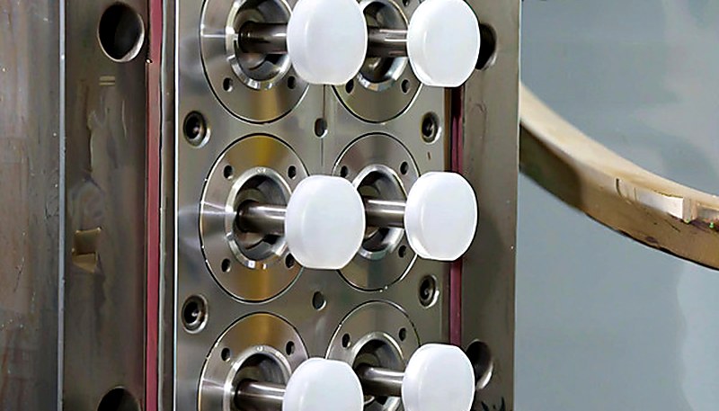
Mikrogeformte Teile Nahaufnahme
Eine Entformungsschräge beim Spritzgießen ist die bewusst in jede senkrechte Fläche einer Formkavität eingebrachte Verjüngung. Diese leichte Neigung lässt das Bauteil nach dem Abkühlen und Aufschrumpfen auf den Kern frei herausgleiten. Ohne sie haftet das Teil wie durch eine Vakuumdichtung am Stahl, und das Auswerfen wird zum Kampf zwischen Auswerferstiften und Werkzeugoberfläche.
Der Anzugswinkel wird in Grad von der vertikalen Achse der Werkzeugöffnungsrichtung gemessen. Ein 1-Grad-Anzug bedeutet, die Wand neigt sich nach außen um etwa 0,0175 mm pro mm Tiefe. Bei einer 50 mm tiefen Tasche ergibt das etwa 0,87 mm Freiraum pro Seite oben. Das klingt gering, macht aber den Unterschied zwischen sauberem Auswurf und einem feststeckenden Teil.
Jede vertikale Oberfläche in Ihrem Bauteil benötigt Schrägung. Dazu gehören Außenwände, innere Rippen, Ansätze, Taschen und sogar Durchgangslöcher. Wenn eine Oberfläche parallel zur Formöffnungsrichtung verläuft und keinen Kegel hat, wird das Bauteil beim Auswerfen schleifen, wodurch Kratzer, Riefen oder Verzug entstehen.
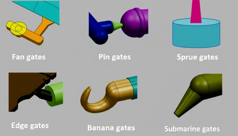
Warum ist der Anzugswinkel für die Teilequalität wichtig?
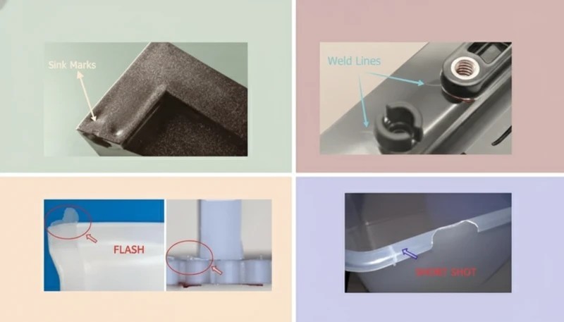
Dieser Abschnitt erläutert die Bedeutung der Entformungsschräge für die Bauteilqualität und ihre Auswirkungen auf Kosten, Qualität, Termine und Beschaffungsrisiken. Sie beeinflusst unmittelbar Bauteiloptik, Maßgenauigkeit, Werkzeugstandzeit und Zykluszeit. Haftet ein Bauteil im Werkzeug, muss das werkzeugseitige Auswerfersystem2 stärker arbeiten. Auswerferstifte hinterlassen Abdrücke, und auf der Oberfläche entstehen Ziehspuren. Im schlimmsten Fall reißt oder verformt sich das Bauteil vor dem Lösen.
Ungenügender Anzug beschleunigt auch den Werkzeugverschleiß. Bei jedem Zyklus kratzt das Teil während des Auswerfens an der Hohlwand entlang. Über 100.000 Zyklen poliert und schrammt diese konstante Reibung die Stahloberfläche. Ein Werkzeug, das 500.000 Zyklen halten sollte, muss möglicherweise nach 200.000 poliert oder nachbearbeitet werden.
Auf der Produktionsseite verzögern schwer auswerfbare Teile den Taktzyklus. Wenn Ihr Bediener das Teil manuell herausklopfen muss oder der Roboter Schwierigkeiten hat, es zu greifen, verlieren Sie Sekunden pro Taktzyklus. Im großen Maßstab summiert sich das zu realem Geld. Eine 3 Sekunden Verzögerung bei einem 30 Sekunden Taktzyklus bedeutet einen Kapazitätsverlust von 10 Prozent.
"Ein Entformungswinkel von 1 Grad kann die Auswerfkraft gegenüber einer Konstruktion ohne Entformungsschräge um bis zu 50% reduzieren."True
Der Kegel durchbricht den Vakuumeffekt zwischen dem schrumpfenden Kunststoff und dem Kern des Werkzeugs. Selbst ein kleiner Winkel verringert den Reibungskoeffizienten beim Auswerfen dramatisch und reduziert die benötigte Kraft des Auswerfersystems.
"Wenn das Werkzeug genügend Auswerferstifte hat, ist keine Entformungsschräge erforderlich."False
Mehr Auswerferstifte verteilen die Kraft besser, aber sie können die grundlegende Reibung zwischen einer parallelen Wand und dem schrumpfenden Plastik nicht überwinden. Ohne Schrägung konzentrieren die Stifte die Kraft nur auf kleinere Bereiche, was das Risiko von Stiftmarkierungen und Bauteilverformung erhöht.
Was sind die Standard-Anzugswinkel?
Es gibt keinen einzigen korrekten Schrägungswinkel – er hängt von Material, Oberflächengüte, Tiefe und Toleranzanforderungen ab. Aber hier sind die Werte, die in der Praxis bei Tausenden von Produktionsformen funktionieren.
| Oberfläche | Mindestschrägung | Empfohlener Auszug | Anmerkungen |
|---|---|---|---|
| Poliert (SPI A-1 bis A-3) | 0.5° | 1° | Glatte Oberfläche lässt sich leicht abziehen |
| Standard (SPI B-1 bis B-3) | 1° | 1.5° | Leichte Bearbeitungsspuren |
| Feine Textur (VDI 12-24) | 1° | 1,5° bis 2° | Pro Texturtiefenstufe 1° hinzufügen |
| Mittlere Textur (VDI 27-33) | 1.5° | 2° bis 3° | Textur verankert sich auf der Bauteiloberfläche |
| Starke Textur (VDI 36-45) | 2° | 3° bis 5° | Tiefe Maserung wirkt wie Mikro-Hinterschnitte |
| Poliert, keine Zugentlastung | 0° | Nicht empfohlen | Nur für niedrige Strukturen unter 10 mm |
Die Faustregel, die ich verwende: Beginnen Sie mit 1 Grad pro Seite für polierte Oberflächen, fügen Sie 1 Grad für jede Erhöhung des Strukturgrades hinzu und gehen Sie nie unter 0,5 Grad für alles, was tiefer als 10 mm ist. Wenn Ihr Kunde wegen Maßbeschränkungen gegen den Anzug argumentiert, zeigen Sie ihm die Kalkulation der Nachbearbeitungskosten gegenüber einer 0,5-Grad-Abschragung.
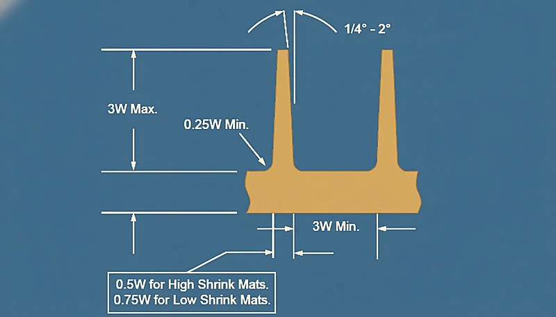
Bei inneren Merkmalen wie Rippen und Ansätzen ist die Schrägungssituation kritischer. Das Plastik schrumpft beim Abkühlen auf den Kern, wodurch ein fester Halt entsteht. Rippen sollten mindestens 0,5 Grad pro Seite haben, aber 1 Grad ist sicherer. Ansätze benötigen außen mindestens 0,5 Grad, und das innere Loch sollte ebenfalls geschrägt sein, wenn es von einem Kernstift geformt wird.
Wie beeinflusst Materialschrumpfung die Schrägungsanforderungen?
shrinkage3 ist der Grund, warum Entformungsschrägen erforderlich sind. Wenn Kunststoff in der Form abkühlt, schwindet er. Bei becher- oder kastenförmigen Bauteilen zieht diese Schwindung die Wände fest auf den Formkern. Je höher die Schwindungsrate, desto fester der Sitz und desto größer der erforderliche Entformungswinkel.
| Werkstoff | Schrumpfungsrate | Min Auszug (Poliert) | Mindestschrägung (texturiert) |
|---|---|---|---|
| ABS | 0.4–0.7% | 0.5° | 1.5° |
| Polycarbonat (PC) | 0.5–0.7% | 0.5° | 1.5° |
| Nylon 6 (PA6) | 0,5–1,5°TP3T | 1° | 2° |
| Nylon 66 (PA66) | 0.8–2.0% | 1° | 2.5° |
| Glasfaserverstärktes Polyamid | 0.2–0.8% | 0.5° | 1.5° |
| PP (Polypropylen) | 1.0–2.5% | 1° | 2.5° |
| PE (Polyethylen) | 1.5–3.0% | 1.5° | 3° |
| POM (Polyacetal) | 1.5–2.5% | 1° | 2.5° |
| PBT | 0.8–2.0% | 1° | 2° |
Teilkristalline Werkstoffe wie Nylon, PP und POM schwinden stärker als amorphe Werkstoffe wie ABS und PC. Dadurch sitzen sie fester auf dem Kern und benötigen größere Entformungsschrägen. Glasfaserverstärktes Nylon bildet eine Ausnahme: Die Glasfasern verringern die Schwindung, sodass trotz der höheren Abrasivität gegenüber der Form eine geringere Entformungsschräge als bei unverstärktem Nylon erforderlich ist.
Bei einem PP-Gehäuseprojekt bestand der Kunde auf 0.5 Grad Entformungsschräge bei mittlerer Textur. Die Teile blieben in jedem zweiten Zyklus hängen. Schließlich mussten wir den Kern nacharbeiten und die Entformungsschräge um 1.5 Grad erhöhen — dadurch gingen drei Produktionswochen verloren. PP mit 2.5 Prozent Schwindung auf einer texturierten Oberfläche konnte bei 0.5 Grad nicht funktionieren.
Was geschieht bei unzureichender Entformungsschräge?
Die Symptome zeigen sich unmittelbar in der Fertigung. Folgendes ist in aufsteigender Reihenfolge des Schweregrads zu beobachten:
Erstens: Ziehspuren. Die Bauteiloberfläche erhält parallele Kratzer in Auswerfrichtung. Bei polierten Teilen ist dies sofort sichtbar und führt zur optischen Ausschussbewertung. Bei strukturierten Teilen wird die Textur streifenweise glatt poliert; es entsteht eine ungleichmäßige Oberfläche, die sich durch keine Nachbearbeitung beheben lässt.
Zweitens: Auswerferabdrücke. Wenn sich das Bauteil dem Auswerfen widersetzt, konzentrieren die Stifte die Kraft auf kleine Flächen. Dadurch entstehen weiße Spannungsmarken auf der Innenseite, sichtbare Eindrücke der Auswerferstifte oder bei dünner Wand sogar Durchstoßlöcher. In unserem Betrieb gilt auf Sichtflächen jeder Auswerferabdruck mit mehr als 0.1 mm Tiefe als Ausschuss.
Drittens: Bauteilverformung. Lässt sich das Teil nur mit hoher Auswerferkraft entformen, kann es sich verziehen, durchbiegen oder reißen. Dünnwandige Teile sind besonders gefährdet. Die Kraft zum Auswerfen eines Teils ohne Entformungsschräge aus einer tiefen Kavität kann die Festigkeit der Wand übersteigen und bleibende Verformungen verursachen.
Viertens: Formschäden. Die dauerhaft hohen Auswerfkräfte verschleißen mit der Zeit Auswerferbohrungen, verkratzen Kavitätsflächen und können Kerne brechen lassen. Bei einer Form mit tiefen Taschen ohne Entformungsschräge kann ein Stiftwechsel alle 50,000 statt alle 200,000 Zyklen erforderlich sein. Das vervierfacht die Wartungskosten.
"Eine Entformungsschräge von 1 Grad an einer strukturierten Oberfläche kann Schleifspuren beim Auswerfen vollständig vermeiden."True
Die zusätzliche Entformungsschräge schafft Freiraum zwischen dem schwindenden Kunststoff und der strukturierten Stahloberfläche. Dieser Freiraum löst den mechanischen Formschluss zwischen Strukturmuster und erstarrter Bauteiloberfläche und ermöglicht eine saubere Entformung.
"Die Entformungsschräge ist nur bei Sichtteilen relevant — Strukturteile benötigen sie nicht."False
Entformungsschräge ist eine mechanische, nicht nur eine optische Anforderung. Strukturbauteile sind beim Auswerfen denselben Schwindungs- und Reibungskräften ausgesetzt. Strukturbauteile mit engen Toleranzen reagieren sogar noch empfindlicher auf auswerfbedingten Verzug infolge unzureichender Entformungsschräge.
Wie verändern Textur und Oberflächengüte die Anforderungen an die Entformungsschräge?
Hier entstehen die meisten Probleme mit der Entformungsschräge. Eine polierte Werkzeugoberfläche ist im Wesentlichen glatt – das Teil gleitet mit minimaler Reibung heraus. Eine strukturierte Oberfläche weist dagegen mikroskopische Spitzen und Vertiefungen auf, die wie winzige Hinterschneidungen wirken. Beim Schwinden legt sich der Kunststoff um diese Spitzen und erzeugt einen mechanischen Formschluss, der dem Auswerfen entgegenwirkt.
Die branchenübliche Regel lautet: Ergänzen Sie je 0.01 mm Texturtiefe 1 Grad Entformungswinkel. Die meisten Texturanbieter stufen ihre Muster auf einer Skala von fein bis grob ein. Eine feine Sandstrahltextur kann 0.01 mm tief sein und nur 1 zusätzlichen Grad erfordern. Eine tiefe Ledernarbung kann 0.05 mm tief sein und zusätzlich zum Grundentformungswinkel 5 weitere Grad benötigen.
Wenn Sie eine Textur für Ihr Bauteil vorgeben, informieren Sie den Werkzeugbauer immer vor der mechanischen Bearbeitung. Eine Änderung der Oberflächenstruktur nach dem Werkzeugbau erfordert häufig eine erneute Kavitätsbearbeitung für zusätzliche Entformungsschräge. Das ist teuer und kann die Bauteilmaße beeinflussen. In einem Fall ergänzte ein Kunde eine VDI-33-Textur bei einem Werkzeug, das für eine polierte Oberfläche mit 1 Grad Entformungsschräge ausgelegt war. Das Werkzeug musste ausgebaut, die Kavität auf 3.5 Grad nachgearbeitet und erneut poliert werden. Sechs Wochen Stillstand.
Wie berechnen Sie die Entformungsschräge für Ihr Bauteil?
Die Grundberechnung ist einfach. Das Entformungsspiel entspricht dem Tangens des Entformungswinkels multipliziert mit der Tiefe des Merkmals:
Spiel pro Seite = tan(Entformungsschräge) x Tiefe
Beispiel für eine Entformungsschräge von 1 Grad an einer 50 mm tiefen Wand: tan(1°) x 50 = 0.0175 x 50 = 0.87 mm Freiraum je Seite. Bei 2 Grad sind es 1.75 mm je Seite, bei 3 Grad 2.62 mm je Seite.
Die praktische Frage betrifft nicht die Berechnung — sondern ob Ihr Bauteil eine derart große Maßänderung von unten nach oben toleriert. Bei den meisten Einhausungen und Gehäusen ist eine Verjüngung von 1 bis 2 mm über eine 50 mm hohe Wand für den Endnutzer nicht sichtbar. Bei Präzisionskomponenten wie Zahnrädern, Lagersitzen oder Passflächen müssen Sie jedoch möglicherweise engere Entformungsschrägen einhalten oder alternative Auswerfstrategien einsetzen.
| Tiefe (mm) | 0.5° Entformungsschräge | 1° Entformungsschräge | 1.5° Entformungsschräge | 2° Entformungsschräge | 3° Entformungsschräge |
|---|---|---|---|---|---|
| 10 | 0.09 | 0.17 | 0.26 | 0.35 | 0.52 |
| 25 | 0.22 | 0.44 | 0.65 | 0.87 | 1.31 |
| 50 | 0.44 | 0.87 | 1.31 | 1.75 | 2.62 |
| 75 | 0.65 | 1.31 | 1.96 | 2.62 | 3.93 |
| 100 | 0.87 | 1.75 | 2.62 | 3.49 | 5.24 |
Beachten Sie, dass selbst bei einer geringen Tiefe von 10 mm und 0.5 Grad nur 0.09 mm Freiraum entstehen. Das reicht kaum aus, um die Oberflächenreibung zu überwinden, insbesondere bei vorhandener Textur. Deshalb lehnen die meisten Werkzeugbauer Werte unter 1 Grad ab — der Fehlerspielraum ist zu klein.
Welche Fehler treten häufig bei Entformungswinkeln auf?
Häufige Fehler bei Entformungsschrägen sind die Hauptkategorien beziehungsweise Varianten, die in diesem Abschnitt erläutert werden. Nach 20 Jahren im Formenbau treten dieselben Fehler immer wieder auf. Die folgenden verursachen die höchsten Kosten:
Fehler 1: Entformungsschrägen nur an Außenwänden vorsehen. Innenliegende Merkmale wie Rippen, Dome und Verstrebungen werden häufig vergessen. Diese Flächen schwinden wie Außenwände auf den Kern, sind jedoch schwerer auszuwerfen, weil die Auswerferstifte sie nicht direkt erreichen. Jede Rippe benötigt mindestens 0.5 Grad je Seite. Jeder Dom benötigt außen mindestens 0.5 Grad.
Fehler 2: Entgegengesetzte Entformungsrichtungen. Wenn die Entformungsschräge auf der Kavitätsseite in die eine und auf der Kernseite in die andere Richtung verläuft, wird das Teil an einem Ende dicker und am anderen dünner. Dadurch entsteht eine ungleichmäßige Wanddicke, die Verzug und Einfallstellen verursacht. Alle Entformungsschrägen eines Merkmals sollten zur Trennebene hin zusammenlaufen, damit die Wanddicke gleichmäßig bleibt.
Fehler 3: Entformungswinkel an Dichtflächen nicht berücksichtigen. Wird eine Durchgangsbohrung oder ein Fenster durch das Aufeinandertreffen beider Werkzeughälften gebildet, benötigt auch die Verschlussfläche eine Entformungsschräge. Ohne sie wirkt die Stahl-auf-Stahl-Kontaktfläche beim Öffnen des Werkzeugs wie eine Bremse. Wir haben Werkzeuge erlebt, bei denen die Schließkraft der Presse um 20 Prozent erhöht werden musste, nur um die Reibung horizontaler Verschlussflächen ohne Entformungsschräge zu überwinden.
Fehler 4: Die nachträgliche Werkzeugtextur wird nicht berücksichtigt. Einige Kunden planen, nach dem Formen durch Lackieren oder Tampondruck eine Struktur aufzubringen. Wurde der Entformungswinkel für eine polierte Oberfläche berechnet und trägt die Nachbearbeitung zusätzliche Dicke auf, verringert sich das effektive Spiel. Konstruieren Sie stets für den endgültigen Oberflächenzustand und nicht für den Zustand direkt nach dem Formen.
Fehler 5: Keine Entformungsschräge bei tiefen Taschen. Dies ist der mit Abstand teuerste Fehler. Tiefe Taschen ohne Entformungsschräge verursachen fast immer Auswerferprobleme. Wenn die Konstruktion zwingend ohne Schräge auskommen muss, planen Sie von Anfang an einen geteilten oder kollabierbaren Kern ein. Das erhöht die Anfangskosten, vermeidet aber spätere Nacharbeitskosten.
Wie werden Entformungsschrägen bei komplexen Bauteilgeometrien ausgelegt?
Nicht jedes Bauteil ist ein einfacher Kasten mit geraden Wänden. Reale Serienteile weisen Hinterschneidungen, seitliche Merkmale, schräge Bohrungen und asymmetrische Geometrien auf. So legen Sie die Entformungsschräge in typischen komplexen Fällen aus.
Geneigte Flächen. Wenn eine Wand bereits stärker als die erforderliche Entformungsschräge geneigt ist, müssen Sie keine weitere Schräge hinzufügen. Eine Wand, die um 5 Grad von der Vertikalen abweicht, weist bereits 5 Grad Entformungsschräge auf. Fügen Sie nur dann eine Entformungsschräge hinzu, wenn die Fläche näher an der Vertikalen liegt, als es die Mindestanforderung zulässt.
Rippen und Versteifungsstege. Versehen Sie Rippen vom Fuß bis zur Spitze mit Entformungsschräge. Der Fuß ist der dickste Bereich und verbindet die Rippe mit der Wand; die Spitze ist am dünnsten. Eine typische Rippe hat 0.5 bis 1 Grad je Seite, wodurch die Spitze naturgemäß dünner wird. Stellen Sie sicher, dass die Spitze nicht dünner als 0.5 mm wird, da sie sonst nicht vollständig gefüllt wird.
Gewinde und Hinterschneidungen. In der Kavität geformte Außengewinde benötigen eine Entformungsschräge an den Gewindeflanken, wodurch sich das Gewindeprofil ändert. Deshalb verwenden die meisten Gewindeteile in der Serienfertigung Gewindeeinsätze oder Ausschraubkerne statt direkt geformter Gewinde. Müssen Gewinde geformt werden, prüfen Sie gemeinsam mit dem Werkzeugbauer, ob die Gewindelehre nach dem Anbringen der Entformungsschräge weiterhin passt.
Lamellen- und Entlüftungsmuster. Diese Konturen haben dünne Lamellen, die auf beiden Seiten eine Entformungsschräge benötigen. Da sie dünn und tief sind, bereiten sie beim Auswerfen häufig Probleme. Verwenden Sie mindestens 1 Grad je Seite und spezifizieren Sie polierte Werkzeugoberflächen.
Welchen Entwurfswinkel sollten Sie in Ihrem Formen-Design vorgeben?
Hier ist der Entscheidungsrahmen, den ich verwende, wenn ich ein Formdesign auf Schrägungsadäquanz prüfe. Er funktioniert für 95 Prozent aller Produktionsteile:
Step 1: Kennzeichnen Sie jede Fläche, die parallel zur Werkzeugöffnungsrichtung verläuft. Markieren Sie sie in Ihrem CAD-System mit einem Farbcode. Rot für keine Entformungsschräge, Gelb für eine grenzwertige Entformungsschräge (0.5 Grad oder weniger), Grün für eine ausreichende Entformungsschräge (1 Grad oder mehr).
Step 2: Bestimmen Sie für jede rote oder gelbe Fläche die Oberflächenbeschaffenheit. Polierte Flächen kommen mit einer geringeren Entformungsschräge aus. Strukturierte Flächen benötigen eine größere. Erfragen Sie bei Ihrem Strukturlieferanten die für das jeweilige Muster empfohlene Entformungsschräge.
Step 3: Prüfen Sie die Materialschwindung. Gleichen Sie die Schwindungsrate mit der obigen Entformungsschrägentabelle ab. Eine höhere Schwindung erfordert eine größere Entformungsschräge, um die Haftung am Kern zu überwinden.
Step 4: Prüfen Sie, ob die Wanddicke von unten bis oben gleichmäßig ist. Wird die Wand durch die Entformungsschräge an einem Ende zu dick oder zu dünn, muss die Bauteilgeometrie entsprechend angepasst werden. Das Versetzen der Trennebene oder die Änderung des Wandprofils sind in der Regel die einfachsten Lösungen.
Step 5: Prüfen Sie die Konstruktion mit Ihrem Werkzeugbauer, bevor Stahl bearbeitet wird. Eine 30-minütige Konstruktionsprüfung kann wochenlange Nacharbeit ersparen. Ihr Werkzeugbauer weiß aus Erfahrung, welche Merkmale beim Auswerfen problematisch sind.
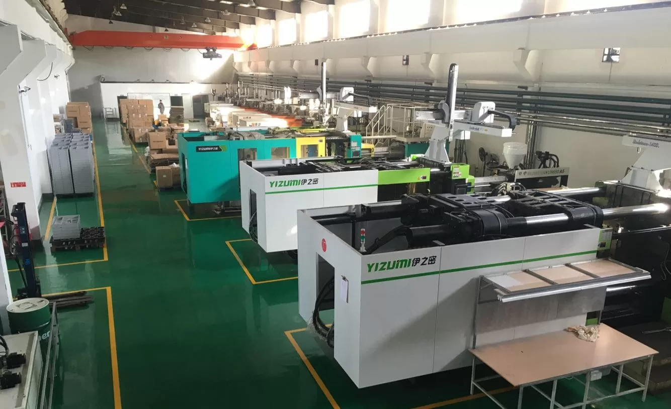
In unserer Fabrik überprüfen unsere Ingenieure jedes Formen-Design auf ausreichenden Entwurf, bevor die Bearbeitung beginnt. Unser Team prüft Rippen, Noppen, strukturierte Seitenwände und die Auswerferrichtung anhand des DFM-Protokolls, sodass entwurfsbedingte Nacharbeiten unter 1% bei über 100 pro Monat aus unserer Shanghaier Fabrik gelieferten Formensätzen bleiben.
Deshalb behandelt unser Team den Schrägungswinkel als ein Produktionsrisiko-Prüfpunkt, nicht als eine kosmetische CAD-Präferenz. Unsere Ingenieure markieren jede Nullschrägungs- oder Grenzschrägungsfläche vor dem Stahlfräsen und bestätigen dann mit dem Kunden, dass die kleine Verjüngung akzeptiert werden kann, bevor die Bearbeitung beginnt.
Häufig gestellte Fragen
Wie groß ist die minimale Entformungsschräge beim Spritzgießen?
Der minimale Schrägungswinkel beträgt 0,5 Grad pro Seite für polierte Oberflächen bei schwindungsarmen Materialien wie ABS oder PC. Für texturierte Oberflächen oder hochschwindende Materialien wie PP oder Nylon liegt das praktische Minimum bei 1,5 bis 2 Grad. Alles unter 0,5 Grad ist extrem riskant und sollte nur bei flachen Merkmalen unter 10 mm Tiefe mit polierten Formoberflächen und robusten Auswurfsystemen versucht werden. In Produktionsumgebungen werden die meisten erfahrenen Werkzeugbauer bei keiner Oberfläche mit mehr als 15 mm Tiefe unabhängig von Oberfläche oder Material eine Schrägung unter 1 Grad empfehlen.
Kann man ohne Entwurfswinkel spritzgießen?
Technisch gesehen ja, aber es wird für Produktionsläufe fast nie empfohlen. Kein Entwurf ist bei sehr flachen Merkmalen unter 10 mm mit polierten Formoberflächen und schwindungsarmen Materialien möglich. Für alles Tiefere verursacht kein Entwurf Auswerferzugsmarken, Stiftdruck, Teileverzug und beschleunigten Formenverschleiß, der die Werkzeuglebensdauer drastisch verkürzt. Wenn Ihr Design unbedingt keinen Entwurf erfordert, planen Sie von Anfang an alternative Auswerfermethoden wie Luftstöße, Abstreifplatten oder zusammenklappbare Kerne ein. Diese Alternativen erhöhen Kosten und Komplexität, sind aber notwendig, um Produktionsprobleme zu vermeiden.
Wie viel Schrägung benötigen Sie für texturierte spritzgegossene Teile?
Die Standardregel ist 1 Grad Entwurf pro 0,01 mm Texturtiefe. Eine feine Textur mit VDI 12 bis 24 benötigt typischerweise 1 bis 1,5 Grad zusätzlichen Entwurf zusätzlich zum Basiswert von 1 Grad. Mittlere Texturen benötigen insgesamt 2 bis 3 Grad pro Seite. Schwere Texturen wie Ledernarbung können insgesamt 3 bis 5 Grad pro Seite erfordern. Bestätigen Sie stets mit Ihrem Texturlieferanten, da deren spezifische Musterstärke den genauen Bedarf bestimmt. Unzureichender Entwurf für Textur ist einer der häufigsten und teuersten Formen-Designfehler in der Branche.
Beeinflusst der Entwurfswinkel die Teiletoleranzen?
Ja, der Schrägungswinkel ändert die Maße des Teils von der Unterseite zur Oberseite der geschrägten Fläche, und dieser Effekt muss in den Toleranzvorgaben berücksichtigt werden. Bei einer 50 mm tiefen Wand mit 1 Grad Schrägung ist die Oberseite der Wand pro Seite etwa 0,87 mm breiter als die Unterseite. Bei den meisten dekorativen Teilen ist diese Verjüngung für den Benutzer unsichtbar. Bei Präzisionsteilen mit Passflächen müssen Sie steuern, welches Ende der Schrägung das kritische Maß einhält, und dies in der Toleranzspezifikation Ihrem Werkzeugbauer klar kommunizieren, um Montageprobleme zu vermeiden.
Was ist der Unterschied zwischen Entwurfswinkel und Konus?
Im Spritzgusskontext beziehen sich Schrägungswinkel und Verjüngung (Taper) auf dasselbe geometrische Merkmal, das als die absichtliche Neigung definiert ist, die auf vertikale Flächen für den Teileauswurf angewandt wird. Schrägungswinkel ist der Standardbegriff im Formendesign und wird in Grad von der Formöffnungsrichtung gemessen. Verjüngung wird manchmal im spanenden Kontext verwendet und kann als Verhältnis wie 1 zu 50 angegeben werden. Für praktische Zwecke in Formendesign-Diskussionen sind sie austauschbar, aber es ist immer beste Praxis, Werte in Grad anzugeben, um Verwirrung zwischen Design- und Fertigungsteams zu vermeiden.
Wie fügt man Rippen und Noppen Entwurf hinzu?
Rippen sollten von der Basis, an der sie auf die Wand treffen, bis zur Spitze mit Entwurf versehen werden. Verwenden Sie 0,5 bis 1 Grad pro Seite und stellen Sie sicher, dass die Spitze nicht dünner als 0,5 mm wird, um Füllprobleme während des Formens zu vermeiden. Noppen benötigen auf der Außenfläche mindestens 0,5 Grad Entwurf, und das innere Loch benötigt ebenfalls Entwurf, wenn es durch einen Kernstift gebildet wird. Für Noppen höher als 15 mm sollten Sie den Entwurf auf 1 Grad pro Seite erhöhen, um zuverlässiges Auswerfen zu gewährleisten. Überprüfen Sie stets, dass die Entwurfsrichtungen von Rippen und Noppen mit dem Hauptwandentwurf konsistent sind, um eine gleichmäßige Wandstärke im gesamten Teil beizubehalten.
Welchen Entwurfswinkel benötigt glasgefülltes Nylon?
Glasfaserverstärktes Nylon benötigt typischerweise 0,5 bis 1 Grad Schrägung pro Seite für polierte Oberflächen und 1,5 bis 2 Grad für texturierte Oberflächen. Die Glasfasern reduzieren die Schwindung im Vergleich zu ungefülltem Nylon, was den Schrägungsbedarf aufgrund der Schwindung sogar verringert. Glasfaserverstärktes Nylon ist jedoch abrasiv auf Formoberflächen, daher hilft eine ausreichende Schrägung, Reibung zu reduzieren und die Formlebensdauer erheblich zu verlängern. Die Fasern verändern die grundlegende Schrägungsberechnung nicht, aber die geringere Schwindung bedeutet, dass das Teil den Kern weniger fest umschließt, was Ihnen etwas mehr Spielraum bei minimalen Schrägungswerten lässt als ungefülltes Nylon erlauben würde.
—text Wie wenden Sie Ihr Wissen über Entformungsschrägen im nächsten Projekt an?
Der Schrägungswinkel ist eines dieser Grundprinzipien, die einen reibungslosen Produktionslauf von einem teuren Nacharbeitsprojekt unterscheiden. Die Regeln sind einfach: mindestens 1 Grad pro Seite für polierte Oberflächen, 1 Grad pro Texturgüte hinzufügen, die Materialschwindung berücksichtigen und niemals Stahl fräsen, ohne jede vertikale Fläche auf ausreichende Schrägung zu prüfen.
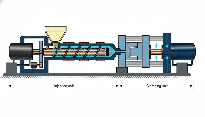
Wenn Sie aus diesem Artikel nur eines mitnehmen, dann Folgendes: Sehen Sie Entformungsschrägen frühzeitig und großzügig vor und prüfen Sie sie gemeinsam mit Ihrem Werkzeugbauer, bevor das Werkzeug gefertigt wird. Ordnen Sie diese Entscheidungen außerdem den Schritten des Spritzgießprozesses zu, denn Entformungsschrägen beeinflussen Füllen, Kühlen, Auswerfen und Prüfen — nicht nur das Erscheinungsbild im CAD. Ein zusätzliches Grad kostet in der Konstruktionsphase nichts. Nach dem Werkzeugbau kostet dieselbe Änderung Wochen und Tausende von Dollar.
Benötigen Sie eine Form, die gleich beim ersten Mal richtig gebaut wird? Nutzen Sie unseren Leitfaden zur Lieferantenbeschaffung um zu prüfen, ob ein Formenbauer Entformungsschrägen, DFM-Risiken und Auswerfnachweise bewerten kann, bevor Sie das Werkzeug beauftragen.
Entformungswinkel: Eine Entformungsschräge ist die in Grad gemessene Neigung an den vertikalen Flächen einer Werkzeugkavität, durch die das Formteil ohne Reibung oder Beschädigung ausgeworfen werden kann. ↩
ejection system: Ein Auswerfersystem ist die mechanische Baugruppe in einem Werkzeug, die das abgekühlte Teil aus der Kavität drückt. Es besteht typischerweise aus Auswerferstiften, Hülsen oder Abstreiferplatten. ↩
Schwindung: Schwindung bezeichnet die Maßverringerung eines Kunststoffteils beim Abkühlen von der Schmelzetemperatur auf Raumtemperatur und wird üblicherweise als Prozentsatz des ursprünglichen Werkzeugmaßes angegeben. ↩