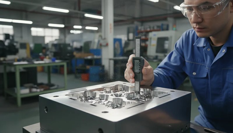
Если при первом испытании формованная деталь из PP оказывается на 0.4 mm меньше требуемого размера, причиной обычно является усадка. Усадка при литье под давлением — это предсказуемое уменьшение размеров пластика при охлаждении, которое компетентные изготовители оснастки учитывают до начала обработки стали.
Это кажется простым, но именно здесь многие проекты идут не по плану. Заказчики часто сопоставляют жёсткий допуск на чертеже с показателем из технического паспорта полимера и ожидают получить номинальный размер уже при первом впрыске. В реальном производстве на окончательный размер детали влияют семейство полимера, толщина стенки, баланс впуска и настройки процесса. усадка1
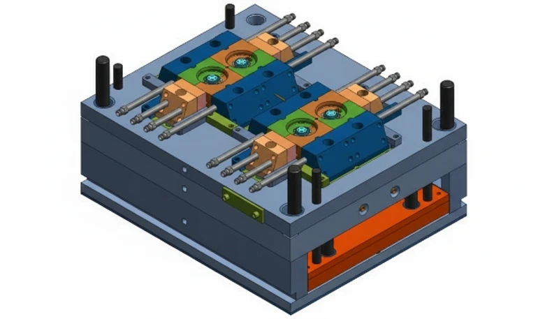
В ZetarMold мы рассматриваем усадку как инженерную задачу проектирования пресс-формы, а не как неожиданность, обнаруженную в последнюю минуту при изготовлении пробных отливок. В ходе DFM мы объединяем данные о материале, геометрию детали и опыт работы с аналогичной оснасткой, чтобы уже при первом испытании пресс-формы приблизиться к целевым параметрам, а не добиваться их многократными корректировками стальной оснастки.
“Полукристаллические материалы дают большую усадку, чем аморфные.”True
Полукристаллические полимеры, такие как PEEK и нейлон, имеют упорядоченную молекулярную структуру и значительно усаживаются при охлаждении. Аморфные материалы, такие как PC и PMMA, имеют хаотичное расположение молекул и меньше изменяются в размерах.
“Усадка — исключительно свойство материала, и конструкция формы не может на нее влиять.”False
Конструкция пресс-формы существенно влияет на усадку за счёт расположения каналов охлаждения и литника, а также равномерности толщины стенок. Правильная конструкция компенсирует склонность материала к усадке.
- Усадка при литье под давлением рассчитывается по формуле S = [(Dm – Dp) / Dm] × 100.
- Типичная усадка формованных пластмасс составляет примерно от 0.1% до 3.0%.
- Аморфные материалы, такие как ABS, PC и PMMA, обычно имеют меньшую усадку, чем полукристаллические материалы, такие как PP, PE, PA и POM.
- Более высокое давление подпитки, равномерная толщина стенок и правильная температура формы помогают уменьшить отклонения размеров.
- Размеры формообразующих полостей обычно назначают с коэффициентом, равным 1 плюс ожидаемая усадка, а затем уточняют по результатам пробного литья.
Что такое усадка при литье под давлением и почему она важна?
Усадка при литье под давлением — это уменьшение размеров, происходящее после заполнения полости при охлаждении, затвердевании и релаксации расплавленного пластика. Она имеет значение, поскольку размеры полости пресс-формы не равны конечным размерам детали: полость необходимо намеренно увеличивать с учётом усадки каждого полимера.
“При компенсации усадки необходимо учитывать переменные пресс-формы и материала.”True
Коэффициенты усадки зависят от марки материала, толщины стенок и условий переработки. Для полной компенсации необходимо одновременно корректировать конструкцию пресс-формы и параметры процесса.
“Все материалы при литье под давлением дают одинаковую усадку.”False
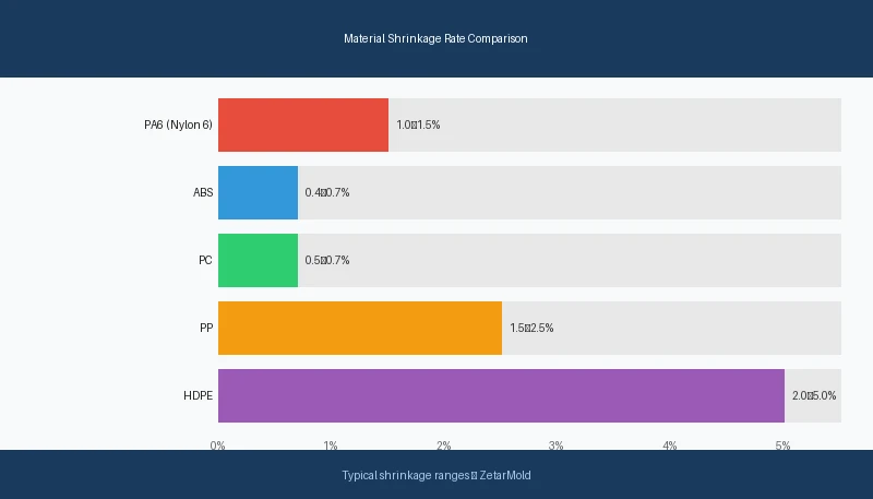
Разные материалы имеют существенно различающиеся коэффициенты усадки. Полукристаллические материалы, такие как PE и PP, дают усадку 1-3%, тогда как аморфные материалы, такие как PC и ABS, — только 0.4-0.7%.
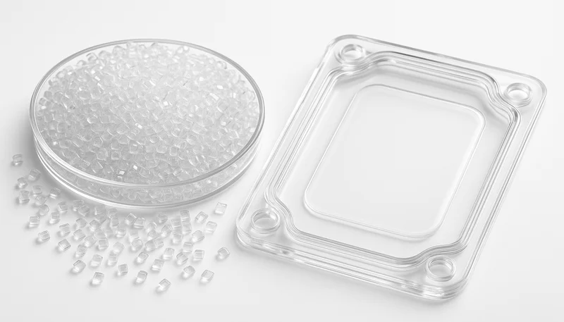
Для большинства пластиковых деталей общая усадка находится в диапазоне от 0,1 % до 3,0 %, однако за ним скрываются значительные различия между материалами. Прозрачная крышка из PC может оставаться относительно стабильной, тогда как корпус такого же размера из PP изменится гораздо сильнее. Поэтому усадка непосредственно связана как с конструкцией литьевой пресс-формы, так и со всем процессом литья под давлением2.
Вопрос определяют два размера. Dm — размер пресс-формы, а Dp — окончательный размер детали после охлаждения. Разница между ними сама по себе не является отходом или ошибкой. Это расчетная компенсация, основанная на поведении выбранного полимера при охлаждении и стабилизации после формования.
Распространенные заблуждения об усадке
Главная ошибка — считать усадку одним числом из технического паспорта. Реальные литые детали реагируют на локальную толщину стенок, расположение литника, эффективность охлаждения и ориентацию. Плоская пластина и ребристый короб могут иметь разную усадку, даже если они изготовлены из одной партии полимера на одной машине.
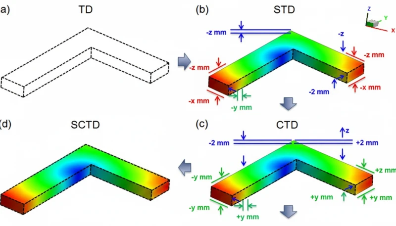
По этой же причине возникает коробление. При равномерной усадке деталь просто уменьшается. Если усадка различается по направлениям или по участкам разной толщины, деталь изгибается, скручивается или теряет прямоугольность. На практике нарушение размеров часто представляет собой проблему неравномерного охлаждения, замаскированную под проблему допусков. контроль усадки3
«Все материалы для литья под давлением дают усадку после формования».True
Каждый термопласт уменьшается в объёме при охлаждении от температуры расплава до комнатной температуры. Величина усадки зависит от типа полимера, содержания наполнителя и параметров процесса, однако базовый механизм усадки универсален.
«Для деталей из PP и ABS можно использовать одинаковые размеры пресс-формы.»False
Усадка PP обычно составляет около 1.5-2.5%, тогда как для ABS она, как правило, ближе к 0.4-0.7%. Полость, рассчитанная на ABS, не обеспечит тех же конечных размеров при переходе на PP.
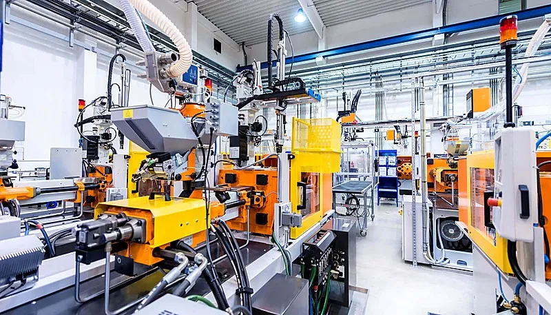
На нашей фабрике в Шанхае анализ усадки начинается до запуска оснастки, поскольку последующая доработка стали полости дорога. У нас работают 45 термопластавтоматов усилием от 90T до 1850T, и самое частое несоответствие возникает, когда заказчик требует ±0.05 mm для детали из полукристаллического PP, а затем спрашивает, почему образцы T1 отклоняются на 0.3-0.5 mm. Обычно это собственное поведение материала, а не небрежное литье.
На нашем заводе в Шанхае работают 45 машин для литья под давлением с усилием смыкания от 90T до 1850T. Контроль усадки входит в каждый проводимый нами анализ DFM. Наиболее частая проблема — заказчики задают жёсткие допуски, например ±0.05 mm, для деталей из полукристаллического PP, а затем удивляются отклонению первых образцов на 0.3-0.5 mm. Это не ошибка процесса, а неотъемлемое поведение материала, которое мы учитываем на этапе проектирования пресс-формы.
Как рассчитать усадку при литье?
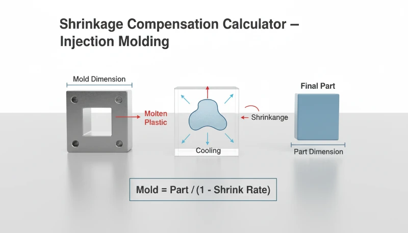
Усадка при формовании рассчитывается по формуле S = [(Dm – Dp) / Dm] × 100. В этой формуле S — процент усадки, Dm — размер пресс-формы, а Dp — размер охлаждённой детали, измеренный после формования.
Логика проста. Предположим, размер полости составляет 100.00 mm, а измеренный после охлаждения размер детали — 98.50 mm. Расчёт выглядит так: S = [(100.00 – 98.50) / 100.00] × 100 = 1.5%. Это означает, что относительно размера полости деталь уменьшилась на 1.5%.
При проектировании оснастки инженеры также выполняют обратный расчет. Если целевой размер детали равен 100.00 mm, а ожидаемая усадка — 1.8%, до обработки стали размер полости должен составлять около 101.80 mm. Иными словами, размеры пресс-формы умножают на единицу плюс коэффициент усадки, а затем подтверждают по образцам.
Такой обратный расчёт практичен, но всё равно требует профессиональной оценки. Значения в технических паспортах часто приводятся диапазоном, поскольку один и тот же полимер может вести себя по-разному при различных параметрах процесса литья под давлением.
«Равномерная толщина стенки — самый эффективный способ контроля усадки».True
Постоянная толщина стенок обеспечивает равномерное охлаждение и однородную усадку по всей детали. Изменения толщины стенок более 25% вызывают дифференциальную усадку, приводящую к короблению и утяжинам.
“Добавление каналов охлаждения всегда уменьшает усадку.”False
Каналы охлаждения сокращают время цикла, но не изменяют усадку материала. Они повышают стабильность размеров за счет равномерного охлаждения, однако сам материал усаживается на ту же величину.
Практическое измерение усадки
Профиль выдержки под давлением, время охлаждения, момент застывания литника и температура поверхности пресс-формы влияют на то, в какой участок этого диапазона попадут параметры готовой детали.
Для точных результатов не начинайте контроль размеров сразу после извлечения детали. Многие материалы продолжают релаксировать после формования, особенно толстостенные или полукристаллические марки. Единообразная методика контроля важна не меньше самой формулы. Если одна группа выполняет измерения через 10 минут, а другая — через 24 часа, результаты усадки могут быть несопоставимы.
Корректное исследование процесса отделяет общую усадку от локальных отклонений. Корпус может соответствовать по наружным размерам, но не пройти контроль вокруг отверстий, бобышек или ребер, поскольку эти участки охлаждаются с разной скоростью. Поэтому опытные инструментальные группы измеряют несколько контрольных размеров, а не полагаются на одну общую длину.
При изготовлении серийной оснастки мы обычно начинаем с номенклатуры материалов поставщика, сопоставляем её с аналогичными ранее изготовленными пресс-формами, а затем устанавливаем контрольные этапы испытаний для наиболее критичных размеров. Если к детали предъявляются требования по внешнему виду или функциональности, мы можем отдать приоритет одному размеру для доводки с запасом металла, оставив возможность корректировать остальные зоны посредством оптимизации процесса.
Усадка различных материалов: полукристаллические и аморфные
Семейство материала сильнее всего влияет на усадку, причем полукристаллические полимеры обычно усаживаются больше аморфных. Как правило, усадка аморфных материалов, таких как PC, ABS и PMMA, часто составляет около 0.4-0.8%, а полукристаллических, таких как PP, PE, PA и POM, чаще находится между 1.0% и 3.0% или даже выше для некоторых марок.
Причина заключается в структуре. При охлаждении аморфные пластмассы застывают с более хаотичным расположением молекул, поэтому изменение объема относительно невелико и равномернее. Термопласт с полукристаллической структурой при охлаждении образует упорядоченные области, что увеличивает усадку и может сделать ее более направленной.
Направленная зависимость ещё важнее для армированных марок. Например, стеклонаполненный нейлон может давать одну усадку вдоль потока и другую поперёк него. Такая анизотропия — типичный источник сложностей при проектировании пресс-форм, поскольку бобышки, рёбра и плоские панели после ориентации волокон реагируют по-разному.
| Материал | Тип | Скорость усадки | Типичное применение |
|---|---|---|---|
| PP | Полукристаллический | 1.5-2.5% | Потребительские товары, автомобильные детали |
| PE (HDPE) | Полукристаллический | 1.5-3.0% | Контейнеры, упаковка |
| PA66 (нейлон) | Полукристаллический | 1.0-2.0% | Механические детали |
| POM (ацеталь) | Полукристаллический | 2.0-3.5% | Прецизионные шестерни |
| ABS | Нужно ли это | 0.4-0.7% | Электронные корпуса |
| ПК | Нужно ли это | 0.5-0.7% | Оптические детали, безопасность |
| ПММА | Нужно ли это | 0.2-0.5% | Дисплеи, линзы |
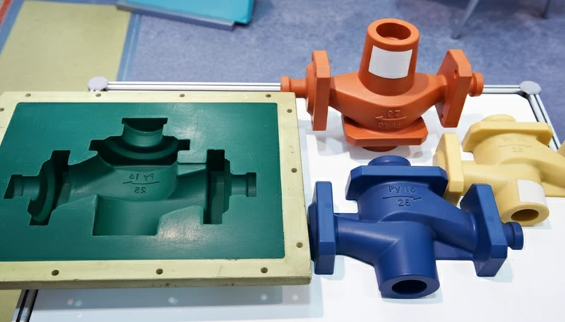
В таблице показано, почему замена материала никогда не является тривиальной задачей. Если клиент переходит с АБС на ПП для снижения стоимости, команде разработки оснастки необходимо пересмотреть размеры полости, баланс литников и допуски. Деталь может выглядеть похожей, но размерные характеристики могут измениться настолько, что потребуется изменение стали или, как минимум, нового технологического окна.
Вот почему анализ материала должен проводиться на раннем этапе. Пресс-форма, которая отлично работает с ABS, может стать нестабильной с POM или PA без перепроектирования стратегии охлаждения и литников. Стоимость материала видна в коммерческом предложении, но скрытые затраты часто проявляются позже в виде доводки инструмента, увеличения времени цикла и дополнительного контроля размеров. При обзорах инструмента мы сопоставляем запросы на смену материала с исходной стратегией полости, потому что замена на более дешевый материал может привести к дорогостоящей размерной нестабильности. То, что кажется простым выбором закупки, может потребовать другого размера литника, пересмотренного охлаждения или дополнительного запаса по металлу на критических посадочных элементах. Это одна из причин, по которой опытные литейщики оспаривают поздние изменения материала, а не считают их безобидными.
Какие 7 факторов влияют на усадку при литье под давлением?
На усадку в литье под давлением больше всего влияют тип материала, толщина стенки, давление подпрессовки, температура формы, температура расплава, расположение литника и геометрия детали. Эти семь переменных определяют, сколько материала попадает в полость, насколько равномерно он охлаждается и остаётся ли усадка однородной или превращается в коробление.
- 1) Тип материала задаёт исходный уровень. Полукристаллические полимеры по природе дают большую усадку, чем аморфные марки, а содержание наполнителя дополнительно меняет её характер. PA с 30 % стекловолокна ведёт себя совершенно иначе, чем ненаполненный PP, даже при одинаковом номинальном размере детали.
- 2) Толщина стенки определяет скорость охлаждения и локальную массу материала. Толстые зоны дольше остаются горячими и продолжают усаживаться, поэтому чаще вызывают утяжины или деформацию соседних поверхностей. Особенно рискованны переходы между тонкими и толстыми участками: деталь одновременно охлаждается с двумя разными скоростями.
- 3) Давление выдержки непосредственно компенсирует потерю объёма до застывания впуска. Для многих пресс-форм эффективное давление выдержки составляет около 60–80 % давления впрыска. При слишком низком давлении полость остаётся недоуплотнённой. Слишком высокое давление может вызвать облой или внутренние напряжения, которые позже проявятся как дрейф размеров.
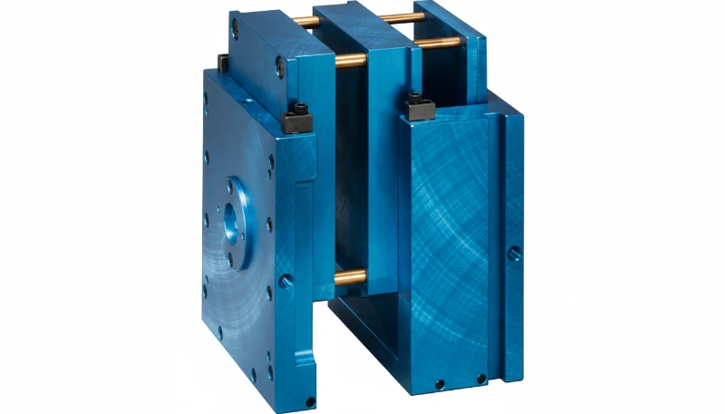
Факторы проектирования и оснастки
- 4) Температура пресс-формы влияет на скорость затвердевания полимера у стенки полости. Более высокая температура может улучшить качество поверхности и текучесть, но часто способствует большей кристаллизации полукристаллических полимеров и тем самым повышает усадку. Более низкая температура может уменьшить общую усадку, однако при чрезмерно интенсивном охлаждении увеличивает замороженные внутренние напряжения.
- 5) Температура расплава задаёт исходное состояние материала. Более горячий расплав обычно лучше заполняет тонкие участки, но при этом из детали нужно отвести больше тепла. Если одновременно не скорректировать охлаждение и выдержку под давлением, окончательные размеры могут измениться непредсказуемо.
- 6) Расположение впуска определяет путь потока и распределение давления. Неудачно размещённый впуск приводит к неравномерному заполнению, уплотнению и ориентации материала. На крупных деталях это один из самых быстрых способов получить разную усадку противоположных углов.
- 7) Геометрия детали усиливает влияние всех остальных факторов. Плоские панели, длинные рёбра, отдельные бобышки и асимметричные стенки нарушают баланс охлаждения. Здесь усадка перестаёт быть только свойством полимера и становится комплексной инженерной задачей, связанной с материалами для литья под давлением, схемой охлаждения и конструкцией элементов.
| Фактор | Типичный эффект | Лучший ответ |
|---|---|---|
| Большая толщина стенки | Повышает риск локальной усадки | Удаление массивных сечений (коркование) |
| Более высокое давление подпрессовки | Уменьшает общую усадку | Настройка профиля подпрессовки до замерзания |
| Неравномерное расположение литника | Увеличивает вариацию по направлениям | Переместить или сбалансировать литники |
Когда эти переменные не сбалансированы, результатом часто становится дифференциальная усадка, а не просто общее уменьшение размера. Направление потока может сокращаться иначе, чем поперечное направление, особенно в стеклонаполненных материалах. Это неравномерное сокращение напрямую ведёт к короблению, выпучиванию стенок, скручиванию рамок и нарушению допусков на сборочных стыках.
Практический вывод: ни один параметр не может исправить неудачное геометрическое решение. Если деталь имеет толстые ребра, подводящие к большой плоской стенке, а литник находится с одного конца, проблему не всегда можно решить только увеличением давления подпрессовки. Лучшим решением может быть изменение соотношения ребер, перемещение литника или перепроектирование охлаждения вокруг горячей точки.
Как компенсировать усадку при проектировании формы?
Усадка компенсируется при проектировании пресс-формы путем масштабирования размеров полости выше целевого размера детали с последующей поддержкой этого размера сбалансированными литниками, охлаждением и настройкой с запасом по металлу. Простое правило: умножить целевую размерность на 1 плюс ожидаемый коэффициент усадки.
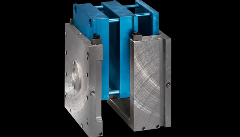
Например, если требуемая конечная ширина составляет 80,00 мм, а ожидаемая усадка — 1,21%, то начальная ширина полости становится 80,96 мм. Это дает инструментальщику реалистичный размер для первого реза. Далее, испытания T1 и T2 показывают, подтверждает ли реальная партия материала, фактическая схема охлаждения и геометрия детали оценку или требует ее незначительной корректировки в большую или меньшую сторону.
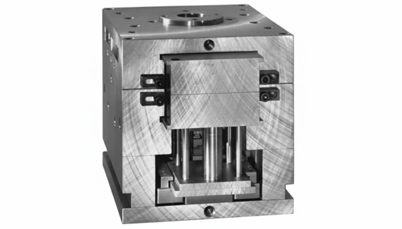
Хорошая компенсация никогда не сводится только к расчетам в таблице. Конструкторы пресс-форм также выбирают положения литников, чтобы сначала заполнить критические зоны, размеры литниковых каналов для поддержания давления и размещают охлаждающие каналы так, чтобы самые горячие зоны не отставали сильно от остальной полости. Для более точных деталей размеры с запасом по металлу планируются намеренно, чтобы после пробных отливок оставалась возможность корректировки.
Здесь важны особенности, специфичные для материала.
Глобальная и локальная компенсация
Если в проекте используется ПП, ПЭ, ПА или ПОМ, мы предполагаем большее размерное изменение и заранее оцениваем допустимость допусков. На оснастке с материалами с меньшей усадкой, такими как АБС или ПК, полость может требовать меньшей компенсации, но размерная стабильность всё равно может быть потеряна при слабом выталкивании, дисбалансе охлаждения или вентиляции.
Мы также разделяем глобальную компенсацию и локальную компенсацию. Корпусу может потребоваться общий масштабный коэффициент, но области вокруг винтов или выравнивающих выступов могут потребовать локальных изменений толщины стали после испытаний. Это нормально. Цель — не угадать идеально с первого раза. Цель — сделать первую версию пресс-формы достаточно интеллектуальной, чтобы её настройка была небольшой, быстрой и предсказуемой.
В обзорах DFM мы часто отмечаем конструкции, где требования к допускам жестче, чем может реально обеспечить выбранный материал. Если заказчик хочет, чтобы большая крышка из PP выдерживала допуски, близкие к механически обработанным, лучшим инженерным решением может быть смена материала, добавление компенсационного зазора в сборке или преобразование одной критической детали в поверхность, подвергаемую последующей механической обработке, вместо того, чтобы заставлять всю деталь работать в нестабильном технологическом окне.
Распространенные проблемы усадки и способы их устранения
Наиболее распространённые проблемы, связанные с усадкой, — заниженные размеры деталей, утяжины, коробление, овальность отверстий и нестабильность размеров. Каждая проблема указывает на свою комбинацию первопричин, поэтому устранение следует начинать с анализа характера дефекта, а не с бессистемного изменения настроек.
Если вся деталь равномерно меньше требуемого размера, прежде всего следует проверить неправильный припуск на усадку в оснастке. Обычно это означает, что коэффициент масштабирования полости был слишком низким либо фактическая усадка материала превышает среднее значение из технического паспорта. Для исправления может потребоваться снятие стали, но сначала необходимо подтвердить стабильность профиля подпитки и момента измерения.
Если утяжины появляются над ребрами или бобышками, причиной обычно является локальная концентрация массы. Более толстый внутренний элемент продолжает усаживаться после затвердевания наружного слоя и втягивает внешнюю поверхность. Типичные решения: уменьшить толщину ребра, увеличить время выдержки, повысить эффективность литника или переместить литник ближе к массивному участку, чтобы полость дольше оставалась под подпиткой.
Если деталь изгибается или скручивается, рассматривайте это как коробление из-за неравномерной усадки. Ищите асимметричные сечения стенок, недостаточное охлаждение с одной стороны или ориентацию материала из-за одностороннего впускного литника. Корректировка процесса может помочь, но если неравномерное охлаждение обусловлено самой формой детали, долговременное решение обычно требует изменения оснастки или конструкции детали.
Проблемы направления потока и многогнёздных форм
Если круглые отверстия становятся овальными или сопрягаемые выступы перестают совмещаться, проверьте влияние направления течения. Армированные материалы могут демонстрировать сильную ориентацию, а даже ненаполненные полимеры могут давать смещение при длинных путях течения. В таких случаях перенос точки впуска или изменение схемы охлаждения часто эффективнее простого повышения давления.
Если размеры различаются между гнездами, прежде чем винить смолу, сравните фактическую работу контуров охлаждения, вентиляцию и баланс впусков. Многогнездные формы усиливают небольшие различия. Если одно гнездо на 3°C горячее остальных, возникает размерный тренд, который кажется случайным, пока данные не сопоставят со схемой формы.
Худшая реакция — бессистемно менять все настройки. Одновременное повышение давления впрыска, снижение температуры пресс-формы и увеличение времени охлаждения может изменить результат, но скроет первопричину. Правильнее зафиксировать один набор параметров, изменять по одной переменной и записывать смещение каждого критического размера. Так устранение неполадок опирается на данные, а не на догадки.
Во всех этих сценариях отказа закономерность одинакова: проблемы усадки легче предотвратить при проектировании формы, чем исправлять после первых пробных отливок. Самые дорогие исправления требуют доработки стали, но обычно их можно избежать, если заранее оценить усадку по реалистичным данным материала и проверенной геометрии оснастки.
Подход ZetarMold к контролю усадки
ZetarMold контролирует усадку, сочетая анализ DFM, реалистичный выбор материала, изготовление оснастки с припуском по стали и обратную связь на основе измерений образцов. Мы не рассматриваем усадку как условное число; для нас это предсказуемое производственное поведение, которое необходимо заложить в оснастку уже при первом анализе конструкции пресс-формы.
Первый шаг — согласование материала и допусков. Если чертеж предусматривает очень жесткий допуск для крупной детали из полукристаллического полимера, мы поднимаем этот вопрос заранее, не создавая ложного впечатления, что впоследствии пресс-форма решит все проблемы. Такое обсуждение часто экономит больше времени, чем любая корректировка оснастки, поскольку возвращает проект к реальным свойствам материала вместо нереалистичных номинальных размеров.
Проверка геометрии и изготовление образцов
Затем мы анализируем геометрию детали на наличие типичных причин усадки: переходов от толстых сечений к тонким, изолированных бобышек, длинных неподкрепленных стенок и литников, создающих однонаправленное течение вдоль наиболее критичных размеров. По результатам анализа мы рекомендуем изменить литники или систему охлаждения либо предусмотреть припуск под последующую доработку в чувствительных зонах до начала изготовления.
Во время испытаний пресс-формы мы измеряем размеры, наиболее важные для сопряжения и работы детали, а не только те, которые проще всего проверить. Если позднее потребуется корректировка, она должна выполняться контролируемыми и обратимыми шагами. Поэтому в наших отчётах по образцам отслеживается фактическое изменение размеров в зависимости от настроек процесса, а не просто указывается результат «пройдено» или «не пройдено».
Кратко суть проста: если усадка анализируется на этапе DFM, большинство размерных отклонений можно спрогнозировать, компенсировать или по меньшей мере локализовать. Если усадку игнорируют до первых пробных отливок, проект обычно расплачивается за это дополнительными испытаниями, доработкой пресс-формы и увеличением срока запуска.
FAQ: часто задаваемые вопросы об усадке при литье?
Что такое нормальный коэффициент усадки в инжекционном формовании?
Нормальная усадка составляет примерно от 0.1% до 3.0% в зависимости от семейства полимера, содержания наполнителя, толщины стенки и условий переработки. У аморфных материалов, таких как ABS и PC, она часто ниже 1.0%, тогда как у полукристаллических материалов, включая PP, PE, PA и POM, часто превышает 1.0% и в некоторых изделиях может достигать или превышать 3.0%. Значение для расчёта оснастки следует определять по техническому паспорту и реальному опыту формования деталей схожей геометрии, а не только по усреднённому показателю.
Почему ПП сжимается больше, чем АБС?
PP обычно даёт большую усадку, чем ABS, поскольку PP является полукристаллическим материалом и при охлаждении образует упорядоченные области, что увеличивает объёмное сокращение. ABS — аморфный материал, поэтому его молекулярная структура фиксируется более хаотично и после формования, как правило, обеспечивает меньшее и более равномерное изменение размеров. На практике это различие определяет, насколько необходимо увеличить размеры полости и насколько строго следует контролировать охлаждение и выдержку под давлением, если конечные размеры критичны.
Как уменьшить усадку при литье под давлением?
Усадку снижают правильным выбором материала, обеспечением более равномерной толщины стенок, достаточным давлением выдержки, сбалансированным охлаждением и корректным исходным размером полости. Во многих пресс-формах быстрее всего помогает оптимизация давления уплотнения и эффективности литника, поскольку до застывания в полость поступает больше материала. Уменьшение локальной массы вокруг рёбер и бобышек также эффективно, поскольку толстые участки продолжают усаживаться после затвердевания наружного слоя.
Может ли усадка вызвать коробление?
Да, неравномерная усадка детали вызывает коробление. Если одна сторона охлаждается быстрее, усадка в одном направлении больше либо отдельный элемент дольше остаётся горячим, деталь изгибается или скручивается вместо равномерного уменьшения размеров. Поэтому коробление обычно связано с разницей усадки, а не просто с отклонением размера. Армированные материалы особенно чувствительны, поскольку ориентация волокон может существенно различать усадку вдоль и поперёк потока.
Когда следует учитывать усадку при разработке формы?
Усадку следует учитывать до начала обработки стали пресс-формы, желательно на этапе DFM и анализа литниковой системы. После механической обработки полости исправление ошибочно принятого коэффициента усадки обходится значительно дороже, поскольку для восстановления целевых размеров могут потребоваться наплавка стали, повторная механическая обработка или несколько циклов отбора образцов. Раннее планирование также помогает подтвердить, способен ли выбранный полимер реально обеспечить допуск по чертежу без вывода процесса в нестабильное или неэффективное производственное окно.
В чем разница между общей усадкой и дифференциальной усадкой?
Общая усадка — это общее уменьшение размеров всей детали после охлаждения, тогда как дифференциальная усадка представляет собой неравномерное сокращение между участками или направлениями одной и той же детали. Общая усадка в основном изменяет размеры. Дифференциальная усадка изменяет форму и часто вызывает коробление, выгибание стенок или несоосность сборочных элементов. Инженеры уделяют особое внимание дифференциальной усадке в стеклонаполненных материалах, деталях с большой длиной пути течения и деталях с неравномерной толщиной стенок, поскольку такие конструкции значительно более склонны к деформации. T
Усадка в пресс-форме: уменьшение объёма пластиковой детали при охлаждении от температуры расплава до комнатной температуры, измеряемое в процентах от исходного размера пресс-формы. ↩
Компенсация усадки: увеличение размеров полостей пресс-формы на ожидаемый процент усадки, рассчитанный по формуле S = [(Dm – Dp) / Dm] x 100, где Dm — размер пресс-формы, а Dp — размер детали. ↩
Коэффициенты усадки материалов: разные семейства полимеров имеют различный характер усадки. Аморфные материалы обычно дают усадку 0,4–0,7 %, а полукристаллические — 1,0–3,0 %. ↩
>Это различие важно: одна проблема устраняется масштабированием полости, а другая часто требует изменения конструкции или охлаждения.
Нужна экспертная оценка конструкции вашей формы?
Получите заключение DFM, анализ усадки и проверку конструкции пресс-формы от инженерной команды ZetarMold.
Начните свой проект литья под давлением →