 Перейти к содержанию

- Симптом
- Cooling accounts for 50–70% of total cycle time and is the single most controllable variable for improving throughput without sacrificing part quality.
- Melt temperature ranges from 180°C to 350°C depending on material; injection pressure runs 70–140 MPa for most engineering resins.
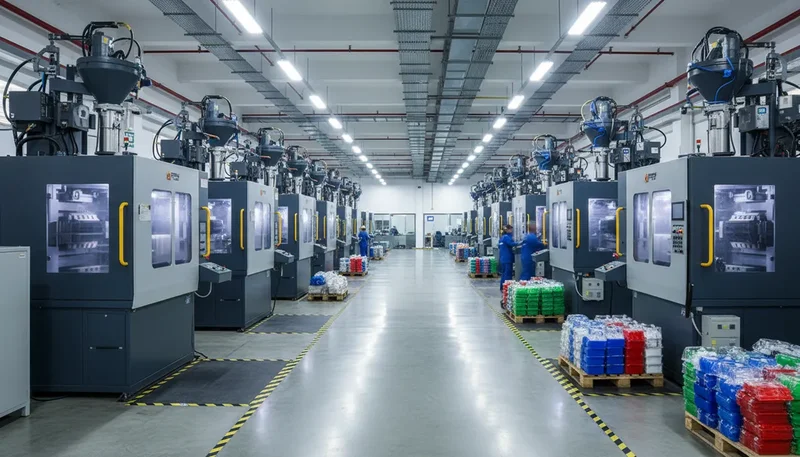
- At ZetarMold, we run 47 machines from 80 to 1,600 tonnes across 3 shifts, averaging a 15-day T1 sample lead time with a 92% first-article pass rate.
What Is the Injection Molding Process and Why Does Each Step Matter?
Сайт литьё под давлением process is a cyclical manufacturing method in which molten термопластик1 is injected under high pressure into a precision steel mold, where it cools and solidifies into a finished part — a complete cycle runs 10 to 180 seconds depending on part geometry and material. Each of the five process steps is not just a sequence but a dependent system: the clamping force you set in step one determines whether you get flash in step two; the packing pressure in step three controls the sink marks that appear after cooling in step four. Get any step wrong and the defects compound through the rest of the cycle.
In our factory at ZetarMold, we process over 400 different materials across 47 injection molding machines. One thing we have learned across millions of production cycles: most quality problems trace back to a parameter set incorrectly at one specific step — not to a global “bad process.” Understanding the function and parameters of each step individually is what makes the difference between a process that produces 50,000 good parts a day and one that requires constant operator intervention.
The five core steps — Clamping, Injection, Packing/Holding, Cooling, and Ejection — run in a continuous loop, with material preparation (drying, conveying) happening in parallel in the background. Some processes add a sixth step (post-mold operations such as trimming or inspection), and high-complexity parts may include a seventh (in-mold labeling or insert placement). But the five-step core cycle is universal across all injection molding machines, from a 5-tonne lab press to a 5,000-tonne automotive machine.
Step 1: Clamping — Closing and Locking the Mold
Clamping is the first step of every injection molding cycle: the machine’s hydraulic or electric clamping unit closes the two mold halves together and applies a locking force before any plastic enters the cavity. This force must exceed the injection pressure multiplied by the projected part area; if it does not, the mold opens during injection, producing flash — thin fins of plastic along the parting line that require manual trimming and reduce part quality.
Clamping force is measured in tonnes. The correct clamping force for a given part is calculated as: Projected area (cm²) × Cavity pressure (MPa) ÷ 10. For a typical 100 cm² projected-area part running at 40 MPa cavity pressure, the minimum clamping force is 400 tonnes. At ZetarMold, we apply a 10–15% safety margin above the calculated minimum to account for mold wear and pressure spikes during injection. Running with exactly the theoretical minimum clamping force is a common cause of parting line flash that gets misdiagnosed as a gate or injection parameter problem.
“Using a clamping force 10–15% above the calculated minimum prevents parting line flash without damaging the mold.”Правда
The calculated minimum clamping force (projected area × cavity pressure) is a theoretical floor, not a production target. Mold wear, uneven pressure distribution across multiple cavities, and shot-to-shot injection pressure variation all require a safety margin. In our experience, a 10–15% margin above the calculated minimum eliminates flash without over-stressing the parting surface. Consistently over-clamping (>25% above minimum) accelerates mold wear and can deform the parting surface over time, creating the very flash problem you were trying to prevent.
“Maximum available machine tonnage should always be used to ensure the mold stays closed.”Ложь
Using maximum clamping force when it is not required damages the mold. Excessive clamp tonnage crushes parting surface vents, trapping gas in the cavity and causing burn marks and incomplete fill. It also deforms the mold’s parting surface over time, creating a gap that produces flash — the exact opposite of the intended effect. The correct approach is to calculate the required clamping force from first principles and apply a modest 10–15% margin, not to default to maximum machine capacity.
Mold open and close time contribute directly to total cycle time. A large mold may take 3–5 seconds to fully close; a small mold closes in under 1 second on a modern electric machine. High-speed mold close sequences (“fast close, slow lock”) are standard on servo-electric machines: the mold closes quickly to within 5–10 mm of full closure, then slows to low pressure and low speed for the final seating to avoid impact damage on mold faces. This sequence protects the parting surface and reduces cycle time simultaneously.
Step 2: Injection — Filling the Mold Cavity
Injection is the step where the screw advances forward, pushing molten plastic through the sprue, runners, and gate into the mold cavity at controlled speed and pressure. Fill time for most parts runs 0.5 to 3 seconds — faster than most people expect. The injection speed profile (not just a single speed) controls how the melt front advances through the cavity, directly affecting weld line location, surface finish, and the risk of jetting or burn marks.
The screw switches from speed control to pressure control at approximately 95–98% cavity fill — this switchover point is called the V/P (velocity-to-pressure) transfer. Before switchover, the machine controls injection speed; after, it controls cavity pressure. Setting the switchover point correctly is critical: too early (at 90% fill) leaves short-shot risk; too late (at 100% fill or beyond) over-packs the cavity, producing stress cracks and part sticking. We set V/P transfer at 97–98% fill on all new tools at ZetarMold as the starting point and adjust based on first shots.
| Материал | Melt Temp (°C) | Давление впрыска (МПа) | Скорость впрыска | Примечания |
|---|---|---|---|---|
| PP (полипропилен) | 200–270 | 70–100 | Medium-fast | Gate freeze at low temp — watch V/P timing |
| ABS | 200–260 | 70–130 | Средний | Burn marks at high speed, jetting at low speed |
| PC (поликарбонат) | 260–320 | 80–140 | Slow-medium | High viscosity — needs elevated barrel temp |
| Nylon PA66 | 260–290 | 80–140 | Быстрый | Low viscosity — fill quickly to avoid premature freeze |
| POM (Acetal) | 180–220 | 80–130 | Средний | Gas can build if venting is inadequate |
| TPE/TPU | 170–230 | 50–100 | Slow-medium | Prone to jetting — avoid high gate speed |
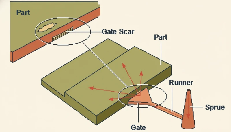
Gate design determines how the melt enters the cavity and is one of the most important decisions in литьевая форма design. A submarine (tunnel) gate shears at part ejection, leaving a clean vestige on the non-cosmetic side. An edge gate is easier to design but leaves a visible gate mark requiring trimming. A hot runner valve gate eliminates the gate mark entirely and reduces cycle time by removing runner solidification from the critical path. For multi-cavity tools running high-cosmetic parts, hot runner valve gates are standard — the added tooling cost is recovered in lower piece-part cost within 30,000–50,000 shots in most applications.
At ZetarMold, the most frequent first-shot fill problem we encounter is weld line position — not short shot. When weld lines appear on Class-A surfaces, the root cause is almost always gate location, not injection speed or temperature. We use анализ течения в пресс-форме3 before cutting steel on every production tool. In 2024, pre-tool simulation identified suboptimal gate locations on 12 of 38 new programs reviewed, saving an average of 1.8 tooling modification cycles per affected tool.
Step 3: Packing and Holding — Compensating for Shrinkage
Packing (also called holding) is the step immediately following cavity fill, where the machine maintains pressure on the melt as it begins to cool and shrink. Without packing pressure, shrinkage during solidification creates sink marks on thick walls, voids inside the part, and dimensional undersizing. This step runs 2–10 seconds and directly sets the final part weight, dimensions, and surface quality.
Packing pressure is typically set at 50–80% of injection pressure. Too high a packing pressure over-packs the cavity: the gate seals under excess pressure, creating residual stress in the part that causes stress whitening, warpage after demolding, or cracking in service. Too low a packing pressure under-fills the cavity through the gate freeze-off period, producing sink marks on the surface above thick wall sections. The correct packing pressure is the minimum pressure that produces a part at target weight — we determine this empirically on first shots by reducing packing pressure until part weight drops by more than 0.1%, then adding 5–10% margin.
| Symptom | Предотвращает образование утяжин на противоположной поверхности | Corrective Action |
|---|---|---|
| Sink marks | Операторы должны носить термостойкие перчатки и защитные очки вблизи зоны сопла машины, где температура расплава для большинства инженерных пластиков превышает 250 градусов Цельсия. Современные машины оснащены блокируемыми защитными ограждениями, которые останавливают механизм смыкания при открытии. Надлежащая вентиляция необходима при обработке таких материалов, как ПВХ или ацеталь, которые выделяют вредные пары при рабочих температурах. Регулярные проверки гидравлической системы предотвращают утечки, создающие риск скольжения и возгорания в производственном цехе. В ZetarMold все операторы проходят сертифицированную программу обучения технике безопасности перед запуском производства, а каждая машина проходит ежеквартальную проверку блокировок безопасности для обеспечения корректной работы систем аварийной остановки. | Increase packing pressure 10% or extend hold time by 1s |
| Warpage after demolding | Over-packing + uneven cooling | Reduce packing pressure; balance cooling channels |
| Part sticking in cavity | Over-packing near gate | Reduce packing pressure; check V/P transfer timing |
| Короткий выстрел | Insufficient fill before packing | Move V/P transfer later; increase injection speed |
| Dimensional variation shot-to-shot | Inconsistent gate freeze-off timing | Adjust mold temperature; verify barrel temperature uniformity |
Gate freeze time — the moment the gate solidifies completely, sealing the cavity — sets the maximum effective packing time. Any packing time beyond gate freeze has no effect on the part because no more material can enter the cavity. Determining gate freeze time experimentally (by incrementally increasing hold time and measuring part weight until weight plateaus) is the most reliable way to set hold time. In our experience, most production tools run with 20–30% more hold time than necessary because the gate freeze time was never experimentally verified — this wastes cycle time without quality benefit.
Step 4: Cooling — The Longest and Most Critical Phase
Cooling is the step where the injected and packed part solidifies inside the closed mold before ejection — and it accounts for 50–70% of total cycle time for most parts. Reducing cooling time is the highest-leverage improvement available in injection molding production. A 10-second cooling time reduction on a part with 100,000 annual cycles saves 278 machine-hours per year: at $80/hour machine rate, that is $22,000 in annual savings from a single process adjustment.
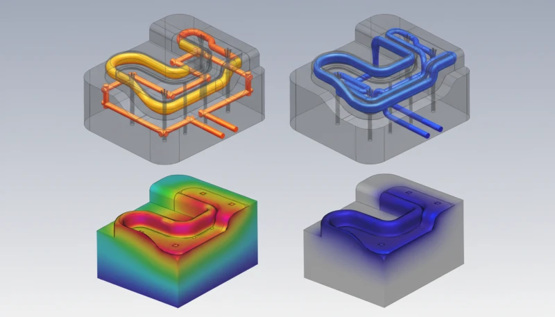
Cooling channel design is the primary determinant of cooling efficiency. Conventional straight-drilled channels are limited to a minimum distance of 10–15 mm from the cavity surface due to drilling constraints. Conformal cooling channels — manufactured by additive (3D printed steel) tooling inserts — follow the contour of the mold cavity, maintaining a uniform 8–10 mm distance regardless of part geometry. At ZetarMold, we documented 28% cycle time reduction on a 1.2 mm wall ABS housing program when switching from straight-drill to conformal cooling channels in 2024. For parts with complex curves, conformal cooling is almost always justified when annual production exceeds 200,000 cycles.
Mold temperature is the other key cooling variable. A lower mold temperature shortens cooling time but must be balanced against part quality: surface gloss, weld line appearance, and dimensional stability can all deteriorate if the mold is too cold. Most amorphous resins (ABS, PC, PS) run at 30–80°C mold temperature; semi-crystalline resins (PP, PA, POM) run at 40–100°C to allow adequate crystallization before ejection. Running a semi-crystalline resin at too low a mold temperature forces rapid crystallization that locks in residual stress — the part appears fine at ejection but warps progressively over the next 24–48 hours as stress relaxes at room temperature.
“Cooling time accounts for 50–70% of total injection molding cycle time and is the highest-leverage variable for throughput improvement.”Правда
Fill and pack steps run 1–5 seconds combined for most parts, but cooling must continue until the part reaches sufficient rigidity for ejection without distortion. For a 40-second total cycle, cooling typically runs 20–28 seconds. Since cooling time scales with wall thickness squared (t_cool ∝ wall²), reducing nominal wall thickness from 3 mm to 2.5 mm cuts cooling time by 31% — often the fastest way to improve cycle time without changing the cooling system itself.
“The mold temperature controller setting directly controls the temperature at the cavity surface.”Ложь
The mold temperature controller sets the coolant inlet temperature, not the cavity surface temperature. The actual cavity surface temperature depends on coolant flow rate, channel proximity, mold steel thermal conductivity, and cycle time. A poorly designed cooling system can show 15–30°C variation across the cavity surface even with a precisely controlled coolant temperature. Measuring actual mold surface temperature with a contact pyrometer — not relying solely on the controller setpoint — is the only reliable method for diagnosing uneven cooling and the warpage or differential shrinkage it causes.
Cooling uniformity is as important as cooling time. Differential cooling rates across the cavity cause warpage: the hot side shrinks more than the cold side, bowing the part toward the hotter mold face. Symmetric cooling channel layout — equal channel density, diameter, and flow rate on both core and cavity sides — is the baseline requirement. For complex parts with unavoidably asymmetric geometry, we use mold flow analysis to model cooling uniformity and identify hotspots before building the tool.
Step 5: Ejection — Removing the Part Without Damage
Ejection is the final step: the mold opens and the ejection system pushes the solidified part out of the cavity. This step takes 1–3 seconds but is disproportionately responsible for surface defects (ejector pin marks, scratches), dimensional errors (part distortion during ejection), and production downtime (stuck parts requiring manual retrieval). Designing ejection correctly from the start prevents most of these issues.
Draft angle is the first line of defense for clean ejection. Without adequate draft, the part grips the steel core surface as it shrinks during cooling, requiring high ejector force that marks or distorts the part. The rule of thumb: 1° per 25 mm of draw depth is a minimum for textured surfaces; 0.5° per 25 mm is acceptable for polished surfaces. For deep cores (>50 mm), we specify 2–3° minimum draft even on polished steel because the friction over the longer surface area accumulates. We have found that DFM4 violations related to insufficient draft are the single most common cause of first-article ejection failures in our customer designs.
Ejector pin placement must distribute force evenly across the part footprint to prevent distortion. Concentrating ejection force at one end of a long, thin part will bend it during the push-out phase, creating warpage that cannot be corrected downstream. We target ejector pin coverage of at least one pin per 25 cm² of part footprint for thin-wall parts, and place pins over ribs or boss features where wall thickness is locally higher — these thicker sections tolerate ejection force better than thin walls.
Air-assisted ejection is standard on all tools at ZetarMold for parts with deep cores or flexible materials like TPE and PP. Compressed air injected at the core surface at the moment of mold opening breaks the vacuum seal between part and steel, reducing ejector force requirements by 40–60% and eliminating most ejector pin witness marks. The air ejection ports are designed as 0.03–0.05 mm annular gaps around core pins — tight enough to prevent material flash but wide enough to pass air at 4–6 bar. This detail is frequently omitted from tools built to minimize tooling cost, and always added back after the first production run when ejection problems appear.
How Do the Five Steps Work Together: Cycle Time Optimization
Total cycle time is the sum of all five steps, but the steps are not equally weighted. Understanding where the time goes is the first step in optimization: cooling dominates (50–70%), followed by mold open/close (10–20%), injection (5–15%), packing (5–10%), and ejection (2–5%). Any cycle time improvement effort that does not focus primarily on cooling is unlikely to produce significant results.
| Шаг | Time (seconds) | % of Total | Optimization Lever |
|---|---|---|---|
| Clamping (close) | 1.5 | 3.75% | Servo-electric machine; fast-close sequence |
| Injection (fill) | 2.0 | 5.0% | Optimize injection speed profile; gate design |
| Packing/Holding | 4.0 | 10.0% | Determine actual gate freeze time; eliminate excess hold time |
| Охлаждение | 26.0 | 65.0% | Conformal cooling; optimize mold temperature; reduce wall thickness |
| Mold open + ejection | 4.0 | 10.0% | Servo-electric machine; air-assisted ejection |
| Robot/part removal | 2.5 | 6.25% | Side-entry robot; optimize trajectory |
| Total | 40.0 | 100% |
In practice, the fastest cycle time improvements come from three sources: (1) experimentally verifying gate freeze time and eliminating excess hold time — we find 20–30% excess hold time in most tools when first measured; (2) upgrading from straight-drill to conformal cooling on high-production tools; (3) switching from hydraulic to servo-electric machines, which offer 10–30% faster open/close cycles with better repeatability. DFM wall thickness reduction — designing the part thinner where structurally permitted — is the most impactful change of all when it is available, since cooling time scales with wall thickness squared.
Frequently Asked Questions About Injection Molding Steps
Что такое процесс литья под давлением шаг за шагом?
Injection molding follows five sequential steps: (1) Clamping — mold halves close under 50–4,000 tonnes force; (2) Injection — molten plastic fills the cavity in 0.5–3 seconds at 70–140 MPa; (3) Packing/Holding — 50–80% of injection pressure is maintained for 2–10 seconds to compensate for shrinkage; (4) Cooling — the part solidifies for 10–80 seconds, accounting for 50–70% of total cycle time; (5) Ejection — the mold opens and pins push the finished part out. A complete cycle runs 10–180 seconds depending on part size and material.
Сколько времени занимает каждый этап литья под давлением?
For a typical 40-second cycle: clamping takes 1.5 seconds, injection 2 seconds, packing 4 seconds, cooling 26 seconds, and mold open plus ejection 4 seconds. Cooling is always the longest step at 50–70% of total cycle time. Very small, thin-wall parts can complete a full cycle in 10–15 seconds; large automotive bumpers or enclosures may require 120–180 seconds, driven almost entirely by cooling time. Wall thickness is the dominant variable: cooling time scales with wall thickness squared, so a 3 mm wall takes roughly 2.25× longer to cool than a 2 mm wall.
Какие типичные проблемы возникают на каждом этапе литья под давлением?
Clamping: inadequate force causes parting line flash. Injection: high speed causes burn marks or jetting; low speed causes premature freeze and short shots. Packing: too much pressure causes stress cracks and part sticking; too little causes sink marks and underweight parts. Cooling: uneven cooling causes warpage; insufficient time causes dimensional variation and deformation on ejection. Ejection: insufficient draft angles cause surface scratches and part sticking; uneven pin placement causes bending or distortion during push-out. Each defect has a specific parameter root cause traceable to one step.
Какие материалы используются при литье под давлением?
Over 18,000 thermoplastic and thermoset grades are commercially available for injection molding. The most commonly processed are: PP (polypropylene) for consumer goods and automotive; ABS for electronics and housings; PC (polycarbonate) for optical and impact-resistant parts; Nylon (PA6/PA66) for mechanical components; POM (acetal) for precision gears; and TPE/TPU for flexible parts. Material selection is driven by mechanical properties, operating temperature, chemical resistance, regulatory compliance, and cost. At ZetarMold, we process 400+ materials and can recommend specific grades based on your application requirements.
Какова стоимость инъекционного формования за каждый этап?
Machine cost per cycle (not per step) runs $0.01–$0.50 depending on machine size and cycle time. A 200-tonne machine at $80/hr with a 30-second cycle costs $0.67 per minute, or about $0.0033 per second. Material cost is typically 30–50% of piece-part cost. Tooling is a fixed cost amortized over production volume — a $15,000 mold at 100,000 parts adds $0.15 per part. The cooling step dominates machine time cost; reducing cooling time by 20% reduces machine cost per part by approximately 14% for most production programs.
Какие меры безопасности применяются во время цикла литья под давлением?
Operators must wear heat-resistant gloves and eye protection near the machine nozzle area, where melt temperatures exceed 250 degrees Celsius for most engineering plastics. Modern machines include interlocked safety gates that stop the clamping mechanism when opened. Proper ventilation is essential when processing materials like PVC or acetal that release harmful fumes at processing temperatures. Regular hydraulic system inspections prevent leaks that create slip hazards and fire risks on the production floor. At ZetarMold, all operators complete a certified safety training program before running production, and every machine undergoes a quarterly safety interlock verification to ensure emergency stop systems function correctly.
Quick Reference: Ready to Start Your Injection Molding Project?
Изучите 6 этапов литья под давлением: смыкание, впрыск, дожимание, охлаждение, размыкание формы и выталкивание. Экспертное руководство с реальными заводскими данными.
At ZetarMold, we run free DFM reviews on all new programs before quoting tooling. Our 20 years of литьевая форма design and production experience and анализ течения в пресс-форме capability mean we find the issues before they become expensive mold modifications. We process 400+ materials, hold tolerances to ±0.05 mm on critical features, and deliver T1 samples in 15 days from tooling authorization. If you have a part that needs to go from design to first shot, reach out for a free DFM consultation and tooling quote.
-
thermoplastic: Thermoplastic is a polymer material that softens and flows when heated, then solidifies when cooled — a reversible process that enables injection molding, regrinding, and recycling, in contrast to thermoset plastics which permanently cure and cannot be remelted. ↩
-
injection mold design: Injection mold design refers to the engineering process of creating tooling geometry — including cavity, core, runner system, cooling channels, and ejection mechanism — that directly determines part quality, cycle time, and production economics. ↩
-
mold flow analysis: Mold flow analysis is a computer simulation technique used to predict how molten plastic fills a mold cavity, identifying potential defects such as weld lines, air traps, and sink marks before the tool is built — measured by fill pressure, temperature distribution, and cooling uniformity. ↩
-
DFM: DFM (Design for Manufacturability) is a structured engineering review that evaluates part geometry, wall thickness, draft angles, undercuts, and material selection before tooling to eliminate defects and reduce tooling revision cycles. ↩


