 コンテンツへスキップ

- プラスチックは射出温度(200~300°C)から室温まで冷却される過程で、密度が増加し、体積は材料によって1~3%減少します。寸法精度を維持するため、この転移期間中に保圧圧力が材料をキャビティ内に押し込みます。
- Material drying is mandatory for hygroscopic plastics like PA6 and PEEK
- Cycle time breakdown: injection 10%, cooling 60-80%, ejection 5-15%
- Clamp force must exceed injection pressure by 20-30% to avoid flash
- Proper cooling design reduces cycle time by 20-35% versus conventional channels
- Ejection force should be 1.5-2 times the projected part area
- Quality inspection follows each shot: visual, dimensional, and functional checks
Step 1: What Is DFM Review and Why Does It Matter?
Your part geometry is frozen. The tooling quote is on your desk. Before steel cutting starts, there is one decision that determines first-shot success: Design for Manufacturability (DFM) review. We have run DFM checks on over 5,000 projects since 2005, and roughly 40% of first-shot failures trace back to wall thickness over 4mm with inadequate cooling. Fixing these after tooling costs ten times more. For more on 金型設計 fundamentals, see our mold guide.
At ZetarMold, our DFM workflow has been refined over 20 years of mold building. We process 400+ materials and build 100+ molds per month, so we see this tradeoff often. Our team includes 8 senior mold engineers who review every new part for wall thickness uniformity, gate placement optimization, and cooling channel efficiency before tooling approval.
射出成形プロセスを段階的に習得する:DFMレビューからクランプ、射出、パック、冷却、排出、品質検査まで。真
By catching wall thickness variations, insufficient draft angles, and gate location issues before steel cutting, manufacturers avoid sink marks, warpage, and short shots that typically require mold modifications costing $5,000-$50,000 per change.
“All wall thickness variations require mold modification.”偽
Small variations within 2:1 ratio can sometimes be compensated with processing adjustments like pack pressure and cooling time changes. Major variations exceeding 3:1 or causing chronic defects do require mold redesign.
The DFM checklist your engineer should present includes five non-negotiable items. For a broader overview of the entire 射出成形 workflow, see our complete guide. Wall thickness uniformity (target ±10% variation), draft angle adequacy (1-3° minimum), gate type and location rationale, material-specific shrinkage compensation, and cooling channel layout.
Your DFM sign-off should include specific measurements: nominal wall thickness with tolerances (±0.1mm for features under 3mm), expected shrinkage rates by material (0.5% for amorphous, 1.5-2.5% for semi-crystalline), gate size and location rationale, and cooling channel layout verification. If any of these are missing from the DFM report, request them before approving the mold build.
If you are comparing vendors or planning procurement, our injection molding supplier sourcing guide covers RFQ prep, qualification, and commercial risk checks.
Step 2: How Do You Dry and Prepare Materials for Injection Molding?
除湿ホッパー乾燥機で材料固有温度(80–160 °C)で2–6時間樹脂ペレットを乾燥し、水分が0.02%以下になるまで続け、その後密封乾燥空気移送ラインで機械ホッパーに直接供給します。密封袋は倉庫に保管され、吸湿性樹脂は開封後急速に水分を吸収-50%相対湿度のPA6は数時間で0.3%水分に達し、0.02%閾値を遥かに超えます。エンジニアリングプラスチックでは乾燥は任意ではなく、最初の品質ゲートです。
Drying specifications depend on material type. PA6 requires 80-100°C for 4-6 hours. PC needs 120°C for 3-4 hours. PEEK demands 150-160°C for 4-6 hours. Monitor dew point of the drying air—below -30°C indicates properly functioning equipment. Above -10°C means your dryer needs service.
上海工場は90Tから1850Tの47台の射出成形機を稼働し、6つの専用乾燥ステーションがあります。120以上の生産作業員と8人の金型エンジニアで、材料乾燥が急かされた時の状況を経験しています。吸湿性材料には-40°C露点乾燥機を維持し、処理する400以上の材料それぞれの乾燥パラメータを記録します。
| 素材 | Drying Temp (°C) | Drying Time (hrs) | Target Moisture (%) |
|---|---|---|---|
| PA6 | 80-100 | 4-6 | <0.02 |
| PC | 120 | 3-4 | <0.02 |
| 覗き見 | 150-160 | 4-6 | <0.01 |
| ABS | 80-85 | 2-3 | <0.02 |
| POM | 80 | 2-3 | <0.02 |
Non-hygroscopic materials like polypropylene and PE do not require aggressive drying, but surface moisture from condensation should still be removed with a brief 1-2 hour drying cycle at 60-80°C. Skip drying entirely only if the material has been stored in a climate-controlled environment.
含水率の確認は、成形品の表面欠陥や構造的脆弱性を防ぎます。ホッパーへの投入前に、ハロゲン水分計またはカールフィッシャー滴定法を使用して、樹脂の含水率が材料固有の閾値を下回っていることを確認してください。一般的な目標値は、PA6およびPA66が0.2%以下の含水率、ポリカーボネートおよびPETが0.02%以下、PBTが0.05%以下です。当社の上海工場では、加工開始前にすべての生産ロットの含水率を確認しています。再生材は、密閉容器に適切に保管された場合でも、バージン樹脂よりも環境中の湿気を吸収しやすいため、再生材ブレンドを成形する際には特に確認が重要です。この確認を怠ると、スプレーマーク、衝撃強度の低下、寸法不安定さが生じ、成形後のパラメータ調整では修正できません。
Step 3: How Does Clamping and Mold Closing Work?
クランプはトン単位で定格された油圧または機械的力を適用し、18,000–50,000 psiの射出圧力に対して金型パーティングラインを密封します。実用的な規則は単純です:キャビティ投影面積を計算し、ピーク値を乗算します 射出圧力1、その後10-20%の安全マージンを追加します。適切なクランプはフラッシュを防止し、パーティングライン形状を保護し、生産ロット間で寸法の繰り返し精度を維持します。
機械のトンナージ定格は最大値を定義します clamp force2 利用可能です。定格トンナージの60-80%で金型を稼働すると、射出および保圧段階での圧力急上昇に対する十分な安全マージンを維持しながら、最適なエネルギー効率を提供します。
“Clamp force calculation requires 20-30% safety margin.”真
The formula (projected area × injection pressure) gives the theoretical minimum. Adding 20-30% compensates for pressure spikes during filling, thermal expansion of the mold, and variations in material viscosity.
“Higher clamp force always improves part quality.”偽
Excessive clamp force can crush venting channels, trap air causing burn marks, and accelerate mold wear. The goal is sufficient force to keep the mold closed without creating stress concentrations.
Mold closing speed follows a two-stage profile. Approach stage: rapid closing from 200-300 mm/s until the mold faces are within 5-10mm of contact. Positioning stage: slow closing from 5-10 mm/s for final closure to protect mold surfaces and alignment features. Some modern machines add a third low-pressure protection stage at 1-2 mm/s with 5-10 bar clamping pressure before full clamp engagement. This prevents damage if foreign material or a stuck part remains in the mold cavity.
Your mold should have wear plates on both moving and stationary halves to protect alignment surfaces. Guide pins and bushings should be lubricated according to the mold maintenance schedule. Tie bars on the clamp unit should be parallel within 0.1 mm/meter to prevent uneven clamping force distribution. Mold height adjustment on the machine should position the parting line centrally in the stroke to maximize available daylight and minimize tie bar stress.
Step 4: How Does Plastic Melting and Injection Work?
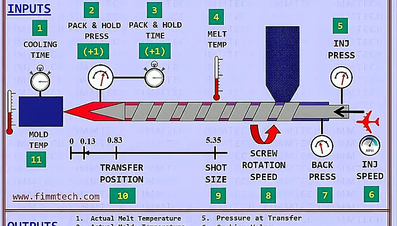
射出は回転スクリューにより加熱バレルで樹脂ペレットを溶融し、均質化された溶融体を50–200 mm/sで金型キャビティに押し込みます。粒状体はホッパーに入り、加熱バレルを通って移動し、回転スクリューにより剪断されます。供給、圧縮、計量ゾーンは材料を輸送、溶融、均質化、計量し、充填時の粘度を安定させます。
Screw rotation speed affects melt quality and throughput. Too slow: insufficient shear heating creates unmelted pellets. Too fast: excessive shear degrades the polymer and causes discoloration. Most engineering resins perform best at 50-120 RPM, with the speed adjusted based on screw diameter and material viscosity.
In our 20+ years of molding experience since 2005, we have accumulated extensive processing knowledge across 400+ materials. Our Shanghai factory maintains standard screw profiles for each material class and customizes for specialty grades. The screw recovery time—the time to accumulate enough melt for one shot—typically runs 2-4 seconds on our machines, contributing 10-15% to total サイクルタイム3.
Injection begins when the screw stops rotating and moves forward as a plunger, forcing the accumulated melt through the nozzle, sprue, runner system, and into the cavity. Injection speed controls surface finish and weld line strength. Fast fill reduces temperature loss but can trap air. Slow fill improves venting but may cause premature freeze-off.
Step 5: What Is Packing and Holding Pressure?
The mold is 95-98% full. The cavity is mostly filled but not packed. Packing pressure compensates for volumetric shrinkage as the plastic cools from melt temperature to ejection temperature—typically 10-15% volumetric shrinkage for semi-crystalline materials. Without adequate packing, parts show sink marks, voids, and dimensional variation that pushes them out of tolerance.
“Packing pressure compensates for thermal shrinkage.”真
As plastic cools from injection temperature (200-300°C) to room temperature, density increases and volume decreases by 1-3% depending on material. Packing pressure pushes material into the cavity during this transition to maintain dimensional accuracy.
“Higher packing pressure always eliminates sink marks.”偽
Excessive packing causes flash at the parting line and ejection problems. Sink marks caused by thick wall sections require design changes like core-outs or rib redesign, not just pressure adjustments.
The critical decision point is gate freeze-off time. The gate must solidify before holding pressure is released, or material flows back out of the cavity. Typical gate freeze times range from 1-3 seconds for edge gates to 0.3-0.8 seconds for sub-gates. Monitor cavity pressure curves—a sharp pressure drop after packing indicates premature gate unfreeze.
Packing pressure profile can be staged rather than constant. Stage 1: High pressure (80-100% of injection) for 20-30% of packing time to drive material into thick sections and corners. Stage 2: Reduced pressure (50-70% of injection) for the remaining time to maintain density without over-packing. This profile reduces sink marks while minimizing flash risk. The transition point is determined by observing the part weight curve and visual inspection of thick sections for sink marks under different pressure levels.
Step 6: How Does Cooling and Solidification Work?
The gate is frozen. The material is packed. The part is dimensionally stable enough to survive ejection but needs to solidify fully before the mold opens. Cooling time dominates cycle time at 60-80% of the total. A 10-second reduction in cooling time on a 25-second cycle is a 40% productivity gain. This is where engineering pays for itself.
従来の冷却では、直径8〜12 mmの直線ドリルチャネルを使用し、間隔は直径の3〜5倍、部品表面からチャネル中心線までの距離は直径の2〜3倍です。これは、単純な形状で均一な肉厚の部品に有効です。ボス、リブ、または肉厚が変化する場合、均一な冷却は困難になります。厚い部分は冷却が遅く、異方性収縮、反り、残留応力を引き起こします。
ZetarMold has implemented conformal cooling channels on high-volume molds since 2013. By following the mold cavity contour rather than straight drilling, we have reduced cooling time by 20-35% for complex parts. This capability, combined with our in-house mold manufacturing facility, allows us to deliver 100+ molds per month with optimized cooling designs.
| 素材 | 2mm Wall (s) | 3mm Wall (s) | 4mm Wall (s) |
|---|---|---|---|
| PP | 8-10 | 12-15 | 16-20 |
| ABS | 10-12 | 15-18 | 20-24 |
| PC | 12-15 | 18-22 | 25-30 |
| PA6 | 10-12 | 15-18 | 20-25 |
| 覗き見 | 15-18 | 22-27 | 30-36 |
Coolant temperature should be 10-20°C below the material’s heat deflection temperature. For PC, set mold temperature at 80-100°C. For PP, 20-40°C works. Higher mold temperatures improve surface finish and crystallinity but extend cycle time. The tradeoff is always cosmetic quality versus throughput.
冷却の最適化により、ハードウェア変更なしで既存の金型でサイクル時間を20-35%削減できます。プロセス調整:部品重量を維持する最小限の保圧時間に減らし、ポンプ限界内で冷却液流量を増加させ、変形を回避する最低金型温度に下げます。金型改造:深いコアを冷却するためのバッフルを追加し、厚肉部に近い位置にチャネルを再配置し、複雑形状にはコンフォーマル冷却を導入します。ROIは通常1000-5000部品以内で実現されます。
Step 7: How Does Mold Opening and Part Ejection Work?
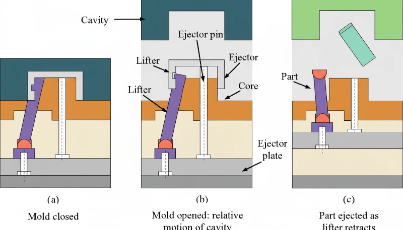
The part is solidified. The cooling time has elapsed. The mold opens. This seems straightforward, but ejection is where 20-30% of injection molding defects occur. Ejection requires overcoming two forces: adhesion of the cooled plastic to the mold steel and mechanical interlocking due to undercuts or insufficient draft. The ejection system must apply enough force to overcome these factors without distorting the part, creating ejector pin marks, or causing part stick-back on the core side.
“Ejection force should be 1.5-2 times the projected part area.”真
金型表面の投影面積50 cm2の場合、75-100 Nの押し出し力はピン跡を最小化しながら確実な押し出しを提供します。過剰押し出しはピン跡と表面損傷を引き起こします。
“More ejector pins always improve ejection reliability.”偽
Excessive pins create surface marks, increase mold cost, and create more failure points. Strategic pin placement at rib intersections and corners is more effective than pin quantity alone.
Ejection system selection depends on part geometry. Straight ejection uses ejector pins for simple geometries. Sleeve ejection handles bosses and cylindrical features. Stripper plate ejection works best for thin-wall cups and caps. For undercuts, you need lifters or angled pins. Choosing the wrong system causes part deformation, sticking, or tooling damage that compounds over thousands of cycles.
Ejector pin placement follows specific guidelines. Place pins in thick sections and rib intersections where ejection resistance is highest. Space pins evenly along the part perimeter to distribute force. Pin diameter should be at least 1.5x the pin length to prevent bending. For polished or textured surfaces, avoid placing pins on visible cosmetic areas.
Mold opening speed affects ejection quality. The opening profile: slow initial opening (5-10 mm/s) for first 10-20mm to allow part separation from core without stress. Rapid opening (100-200 mm/s) for the majority of the stroke to minimize cycle time. Deceleration (20-50 mm/s) for final 50-100mm to avoid slamming the mold open and reducing wear on guide pins and bushings. The deceleration is particularly important for molds with stripper plates or complex lifters that need controlled opening sequences.
Step 8: How Do You Inspect Quality and Monitor the Process?
The part is ejected. It lands in the chute or is robotically removed. Now what? If you assume the process is set and let it run, you will discover defects hours or days later when your customer rejects the shipment. Quality inspection must happen at every shift start, after every material change, and at defined intervals during production. The inspection hierarchy: first article inspection (FAI) on startup, in-process inspection every 50-100 parts, final inspection on each shipment lot.
At ZetarMold, our quality workflow covers IQC (incoming quality control), in-process checks with samples, process inspection, packaging inspection, FQC (final quality control), and OQC (outgoing quality control). We have 10+ QC specialists who verify dimensions, surface quality, and functional requirements on every production run. This 6-step workflow, combined with ISO 9001/13485/14001/45001 certifications, ensures consistent quality across our Shanghai factory operations.
Visual inspection catches 60-70% of defects. Burn marks, flash, short shots, sink marks, and surface blemishes are immediately visible. Train operators to inspect critical cosmetic zones first, then structural features. Use backlit inspection stations for transparent parts and polarized light for birefringence detection in optical components.
| Check | Method | Frequency | Acceptance Criteria |
|---|---|---|---|
| Visual Defects | Lightbox inspection | Every 50 parts | No sink >0.2mm in A-surface |
| Dimensions | CMM/caliper | Every 100 parts | ±0.1mm for ±0.05mm tolerance |
| 重量 | Scale | Every 25 parts | ±2% of target weight |
| Fit/Function | Assembly test | Every shift start | No interference or binding |
| Cosmetic | Golden sample | Every part | クランプ力を計算するには、まず金型のパーティングラインにおける部品の投影面積を求めます。矩形部品の場合、これは長さ×幅(平方インチ)です。その面積に射出圧力(psi)を掛けて分離力(ポンド)を算出し、次にトンに換算します(2,000で除算)。最後に20-30%の安全率を加えます。例:投影面積10平方インチの部品を18,000 psiで成形する場合、分離力は180,000ポンド(90トン相当)となります。25%の安全マージンを考慮すると、少なくとも112~115トンのクランプ能力を持つ成形機を選定することになります。 |
Dimensional inspection verifies parts meet print requirements. Critical dimensions use CMM (coordinate measuring machine) measurement with ±0.01mm accuracy. Standard dimensions get caliper or go/no-go gauge checks. Sample 5 parts per 100-shot cycle for statistical process control, tracking Cp and Cpk values.
現代の機械は射出圧力、保圧圧力、溶融温度、金型温度、サイクル時間、スクリュー回復時間をリアルタイムで追跡します。目標値の±10–20%での警報は自動停止をトリガーし、影響部品を分離し、作業員に警告-不良部品が蓄積前にプロセス変動を捕捉します。
What Are Common Injection Molding Issues and How Do You Troubleshoot Them?
一般的な射出成形不良-シンクマーク、フラッシュ、ショットショット-は調整済みプロセスでも発生します。根本原因と対策を示します。
Sink marks occur when thick sections cool slower than adjacent thin sections, creating surface depressions. The root cause is differential shrinkage. Troubleshooting path: first check wall thickness ratio—if it exceeds 3:1, redesign is required. If wall thickness is acceptable, increase packing pressure in 10% increments while monitoring for flash. Add baffles or bubblers to cool thick sections faster. Reduce melt temperature 5-10°C to minimize initial shrinkage. In severe cases, add external core-outs or gas-assisted molding to eliminate thick sections entirely.
Flash appears at the parting line, around ejector pins, or in vent gaps when material escapes the cavity under excessive injection or packing pressure. Contributing factors include worn mold surfaces, insufficient clamp force, and high melt temperatures that reduce viscosity. Fix flash by increasing clamp force first, then reducing packing pressure, and finally checking mold surface alignment if the problem persists across multiple cavities.
Short shots occur when the cavity is not completely filled, leaving incomplete parts. Common causes include insufficient injection pressure, blocked vents preventing air escape, low melt temperature increasing viscosity, or inadequate shot size. Diagnose by checking injection pressure curves first—most short shots resolve by raising injection speed or pressure by 10-15%. If venting is the issue, clean or deepen vent channels to 0.01-0.02mm depth.
When Should You Adjust vs. Redesign Your Injection Molding Process?
3つ以上の±20%パラメータ変更が失敗した場合、または根本原因に壁厚比3:1以上や不適切な抜き勾配が含まれる場合に再設計に切り替えます。経験則:3つのパラメータを±20%調整しても不良が続く場合、問題は設計関連の可能性が高いです。この点を超えて調整を続けると、問題を解決せずに材料とサイクル時間を浪費します。
“Wall thickness ratio >3:1 requires design modification.”真
When wall thickness exceeds 3:1 ratio, process adjustments cannot eliminate sink marks and warpage. Core-outs, rib redesign, or gas-assisted molding are necessary design solutions.
“All short shots require mold redesign.”偽
Short shots caused by venting issues, material contamination, or improper drying can be fixed through process changes. Only short shots caused by flow length limitations or trapped air in geometry require mold modification.
Design issues that resist process adjustment fall into five categories: wall thickness non-uniformity (causes sink and warp), inadequate draft angles (causes sticking), incorrect gate type or location (causes flow lines and weld lines), insufficient coring (wastes material and cycle time), and sharp corners without fillets (creates stress concentrators). Each of these requires a mold modification, not a parameter tweak.
再設計はエンジニアリング、改造、再検証で5,000–15,000 USDの費用ですが、100,000部品ロットで5–15%スクラップ率の不良部品生産は遥かに高コストです。
How Do You Optimize Injection Molding for Production Efficiency?
まず冷却をターゲットにします。それは各サイクルの60〜80%を占めるため、コンフォーマルチャネルと乱流を介して最適化し、次にパッキングと射出時間を最小化します。サイクル時間は、射出時間(5〜10%)、パッキング・ホールド時間(10〜20%)、冷却時間(60〜80%)、金型開閉時間(5〜10%)、および射出時間(2〜5%)の合計です。冷却が支配的な要因であるため、最適化はまずそこに焦点を当て、その後他の要素に移行するべきです。
ZetarMoldは90Tから1850Tの47台の射出成形機を稼働し、過去1年だけで100以上の金型の冷却を最適化しました。コンフォーマル冷却の導入、冷却液流量の最適化、およびゲートの再設計により、複数の生産ラインでサイクル時間を15-30%削減しました。これらの改善と2005年からの20年以上の経験を組み合わせ、品質を維持しながら競争力のある価格を提供できます。
Cooling optimization targets three areas: channel placement, coolant parameters, and mold material selection. Conformal cooling channels follow the part contour, reducing distance to the cavity surface from 15-25mm (drilled) to 3-8mm (conformal). Coolant flow rate must maintain turbulent flow (Reynolds number above 5,000) for effective heat transfer. Mold materials with higher thermal conductivity like beryllium copper inserts in hot spots can cut local cooling time by 30-40%.
Injection optimization focuses on fill time and melt quality. Fill time optimization: reduce injection time until you see burn marks (too fast) or short shots (too slow), then back off 10%. Velocity-to-pressure switchover point should trigger at 95-98% fill to avoid overshooting. Melt temperature profiling across barrel zones prevents degradation while ensuring complete melting.
| コンポーネント | Typical % of Cycle | Optimization Potential | ROI Timeline |
|---|---|---|---|
| 冷却 | 60-80% | 15-30% | 500-2000 parts |
| Packing/Holding | 10-20% | 10-20% | Immediate |
| Mold Open/Close | 5-10% | 5-15% | Immediate |
| 注射 | 5-10% | 5-10% | 100-500 parts |
| 排出 | 2-5% | 5-10% | 1000-5000 parts |
ROIは部品価値と数量に依存します。1000部品未満での償却は即時実施、1000–5000部品は評価が必要、5000部品以上は戦略的正当性が必要です。
射出成形プロセスに関するよくある質問
よくある質問
What are the 7 steps of injection molding?
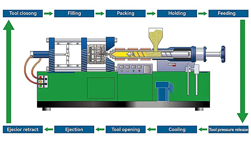
The seven steps of injection molding are: (1) clamping and mold closing, where the machine secures the two mold halves together under high pressure; (2) plastic melting and injection, where heated pellets become molten and are forced into the cavity; (3) packing and holding, where additional material compensates for shrinkage; (4) cooling and solidification, where the part hardens inside the mold; (5) mold opening and part ejection, where the finished part is removed; (6) quality inspection, which covers visual, dimensional, and functional checks; and (7) process monitoring and adjustment, ensuring consistent output throughout production runs.
How long does an injection molding cycle take?
Cycle time ranges from as short as 5 seconds for small thin-wall parts to over 120 seconds for large, thick-wall components. For a typical engineering plastic part with 3mm wall thickness, expect 15-25 seconds per cycle. Cooling dominates the timeline, accounting for 60-80% of total cycle time, while injection fills the cavity in just 0.5-2 seconds. Reducing cooling time through conformal channels or optimized coolant flow is the single most effective way to increase throughput, often cutting cycle time by 20-35% on existing molds.
What is the difference between injection and packing?
Injection is the high-pressure fill phase where molten plastic is forced into the mold cavity at speeds designed to fill 95-98% of the volume, typically completing in 0.5-2 seconds. Packing (or holding) follows immediately at lower pressure, pushing additional material into the cavity to compensate for thermal shrinkage as the plastic cools and contracts. Packing continues until the gate freezes off, usually 2-6 seconds. Think of injection as getting the material into the mold, and packing as keeping it dimensionally accurate as it solidifies.
Why do I need to dry plastic before injection molding?
Hygroscopic materials such as PA6, PC, PET, and PEEK absorb moisture from ambient air over time. During injection molding, this trapped moisture vaporizes instantly at melt temperatures (often above 250°C), causing visible bubbles (splay marks), surface streaks, reduced mechanical strength, and dimensional instability in the finished part. Proper drying at material-specific temperatures (80-160°C) for 3-6 hours reduces moisture content below the critical 0.02% threshold required for defect-free molding. Skipping the drying step remains one of the most common and costly causes of rejected parts in production.
What temperature is used for injection molding?
Injection molding temperatures vary significantly by material type. Polypropylene processes at 180-220°C, ABS at 210-250°C, polycarbonate at 280-320°C, and high-performance PEEK requires 380-420°C. The barrel maintains a temperature gradient from the feed zone (coolest) through compression to the metering zone (hottest), typically with a 20-40°C rise. Mold temperature also plays a critical role: colder molds speed up cycle time but can increase residual stress, while heated molds (60-150°C depending on resin) improve surface finish, crystallinity, and dimensional stability for engineering-grade materials.
How much pressure is needed for injection molding?
Injection pressure typically ranges from 18,000 to 25,000 psi for standard engineering thermoplastics. High-viscosity or glass-filled materials like PEEK or PA66-GF30 can require up to 35,000-50,000 psi. Packing pressure runs at 50-80% of injection pressure. To determine required clamp force, multiply the projected part area (in square inches) by injection pressure, then add a 20-30% safety margin. For example, a 10 square inch part at 18,000 psi needs roughly 90 tons of clamp force, so a 110-115 ton machine provides adequate headroom.
What causes sink marks in injection molding?
Sink marks form when thick wall sections cool more slowly than adjacent thin sections, creating differential shrinkage that physically pulls the surface material inward. The primary causes include wall thickness ratios exceeding 3:1, insufficient packing pressure or hold time, and inadequate cooling channel placement near heavy cross-sections. Practical fixes include coring out thick sections during the DFM stage, increasing packing pressure and extending hold time until gate freeze, and redesigning cooling channels to target thick areas. Process adjustments can resolve mild cases, but severe recurring sinks usually require a mold modification.
How do you calculate clamp force for injection molding?
To calculate clamp force, first determine the projected area of the part at the mold parting line. For a rectangular part, this is length times width in square inches. Multiply that area by the injection pressure in psi to get the separating force in pounds, then convert to tons (divide by 2,000). Finally, add a 20-30% safety factor. For example: a part with 10 square inches of projected area molded at 18,000 psi produces 180,000 pounds of separating force, which equals 90 tons. With a 25% safety margin, you would select a machine with at least 112-115 tons of clamp capacity.


