 Vai al contenuto

- La velocità di chiusura dello stampo segue un profilo a due fasi. Fase di avvicinamento: chiusura rapida da 200-300 mm/s fino a quando le facce dello stampo sono a 5-10 mm dal contatto. Fase di posizionamento: chiusura lenta da 5-10 mm/s per la chiusura finale per proteggere le superfici dello stampo e le caratteristiche di allineamento. Alcune macchine moderne aggiungono una terza fase di protezione a bassa pressione a 1-2 mm/s con una pressione di serraggio di 5-10 bar prima del pieno impegno della chiusura. Questo previene danni se materiale estraneo o una parte incastrata rimane nella cavità dello stampo.
- Material drying is mandatory for hygroscopic plastics like PA6 and PEEK
- Cycle time breakdown: injection 10%, cooling 60-80%, ejection 5-15%
- Clamp force must exceed injection pressure by 20-30% to avoid flash
- Proper cooling design reduces cycle time by 20-35% versus conventional channels
- Ejection force should be 1.5-2 times the projected part area
- Quality inspection follows each shot: visual, dimensional, and functional checks
Step 1: What Is DFM Review and Why Does It Matter?
Your part geometry is frozen. The tooling quote is on your desk. Before steel cutting starts, there is one decision that determines first-shot success: Design for Manufacturability (DFM) review. We have run DFM checks on over 5,000 projects since 2005, and roughly 40% of first-shot failures trace back to wall thickness over 4mm with inadequate cooling. Fixing these after tooling costs ten times more. For more on progettazione di stampi fundamentals, see our mold guide.
At ZetarMold, our DFM workflow has been refined over 20 years of mold building. We process 400+ materials and build 100+ molds per month, so we see this tradeoff often. Our team includes 8 senior mold engineers who review every new part for wall thickness uniformity, gate placement optimization, and cooling channel efficiency before tooling approval.
“DFM review eliminates 80% of potential injection molding defects.”Vero
By catching wall thickness variations, insufficient draft angles, and gate location issues before steel cutting, manufacturers avoid sink marks, warpage, and short shots that typically require mold modifications costing $5,000-$50,000 per change.
“All wall thickness variations require mold modification.”Falso
Small variations within 2:1 ratio can sometimes be compensated with processing adjustments like pack pressure and cooling time changes. Major variations exceeding 3:1 or causing chronic defects do require mold redesign.
The DFM checklist your engineer should present includes five non-negotiable items. For a broader overview of the entire stampaggio a iniezione workflow, see our complete guide. Wall thickness uniformity (target ±10% variation), draft angle adequacy (1-3° minimum), gate type and location rationale, material-specific shrinkage compensation, and cooling channel layout.
Your DFM sign-off should include specific measurements: nominal wall thickness with tolerances (±0.1mm for features under 3mm), expected shrinkage rates by material (0.5% for amorphous, 1.5-2.5% for semi-crystalline), gate size and location rationale, and cooling channel layout verification. If any of these are missing from the DFM report, request them before approving the mold build.
If you are comparing vendors or planning procurement, our injection molding supplier sourcing guide covers RFQ prep, qualification, and commercial risk checks.
Step 2: How Do You Dry and Prepare Materials for Injection Molding?
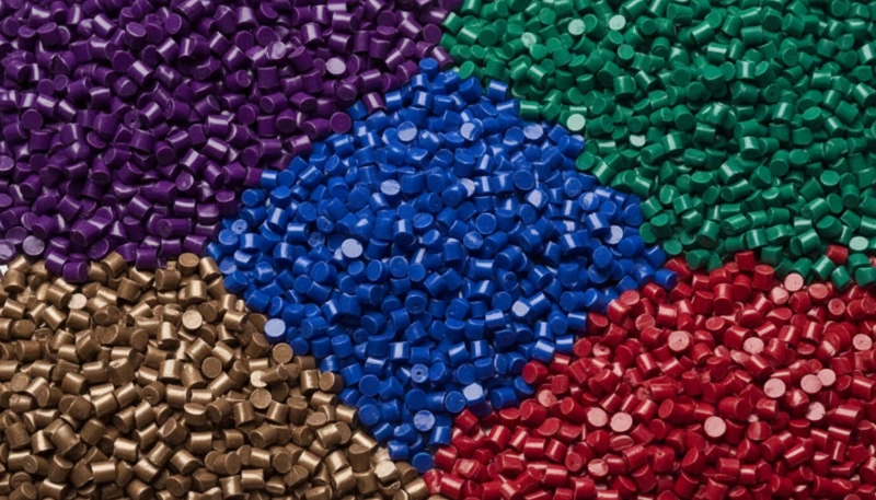
Essiccare i granuli di resina in un essiccatore tramoggia deumidificante a temperature specifiche del materiale (80–160 °C) per 2–6 ore finché l'umidità scende sotto lo 0,02%, quindi alimentarli direttamente nella tramoggia della macchina tramite una linea di trasferimento ermetica ad aria secca. I sacchi sigillati stanno nei magazzini e le resine igroscopiche assorbono umidità rapidamente una volta aperti—il PA6 al 50% di umidità relativa raggiunge lo 0,3% di umidità in ore, ben oltre la soglia dello 0,02%. L'essiccazione non è opzionale per le materie plastiche tecniche; è il primo controllo qualità.
Drying specifications depend on material type. PA6 requires 80-100°C for 4-6 hours. PC needs 120°C for 3-4 hours. PEEK demands 150-160°C for 4-6 hours. Monitor dew point of the drying air—below -30°C indicates properly functioning equipment. Above -10°C means your dryer needs service.
Il nostro stabilimento di Shanghai gestisce 47 macchine per stampaggio a iniezione da 90T a 1850T e abbiamo 6 stazioni di essiccazione dedicate. Con oltre 120 operatori di produzione e 8 ingegneri stampi, abbiamo visto cosa succede quando l'essiccazione del materiale viene affrettata. Manteniamo essiccatori con punto di rugiada di -40°C per materiali igroscopici e documentiamo i parametri di essiccazione per ognuno dei 400+ materiali che lavoriamo.
| Materiale | Drying Temp (°C) | Drying Time (hrs) | Target Moisture (%) |
|---|---|---|---|
| PA6 | 80-100 | 4-6 | <0.02 |
| PC | 120 | 3-4 | <0.02 |
| SETTIMANA | 150-160 | 4-6 | <0.01 |
| ABS | 80-85 | 2-3 | <0.02 |
| POM | 80 | 2-3 | <0.02 |
Non-hygroscopic materials like polypropylene and PE do not require aggressive drying, but surface moisture from condensation should still be removed with a brief 1-2 hour drying cycle at 60-80°C. Skip drying entirely only if the material has been stored in a climate-controlled environment.
La verifica del contenuto di umidità previene difetti superficiali e indebolimenti strutturali nei pezzi stampati. Utilizzare un analizzatore di umidità alogeno o la titolazione di Karl Fischer per confermare che il contenuto di umidità della resina rimanga al di sotto della soglia specifica del materiale prima del caricamento nella tramoggia. Obiettivi comuni includono PA6 e PA66 sotto lo 0,2% di umidità, policarbonato e PET allo 0,02% o inferiore e PBT sotto lo 0,05%. Nella nostra fabbrica di Shanghai, verifichiamo i livelli di umidità su ogni lotto di produzione prima dell'inizio della lavorazione. Il materiale di riciclo — anche se conservato correttamente in contenitori sigillati — assorbe l'umidità ambientale più velocemente della resina vergine, rendendo la verifica particolarmente critica quando si utilizzano miscele di riciclo. Saltare questo controllo porta a striature, ridotta resistenza all'impatto e instabilità dimensionale che nessuna regolazione dei parametri post-stampaggio può invertire.
Step 3: How Does Clamping and Mold Closing Work?
La chiusura applica una forza idraulica o meccanica nominale in tonnellate per sigillare la linea di divisione dello stampo contro pressioni di iniezione di 18.000–50.000 psi. La regola pratica è semplice: calcolare l'area proiettata della cavità, moltiplicare per il picco pressione di iniezione1, quindi aggiungere un margine di sicurezza del 10–20%. La chiusura corretta previene le sbavature, protegge la geometria della linea di divisione e mantiene le dimensioni ripetibili durante le produzioni.
Le potenze nominali delle macchine definiscono il massimo clamp force2 disponibile. Far funzionare uno stampo al 60-80% della potenza nominale garantisce la massima efficienza energetica mantenendo un adeguato margine di sicurezza per i picchi di pressione durante le fasi di iniezione e compattazione.
“Clamp force calculation requires 20-30% safety margin.”Vero
The formula (projected area × injection pressure) gives the theoretical minimum. Adding 20-30% compensates for pressure spikes during filling, thermal expansion of the mold, and variations in material viscosity.
“Higher clamp force always improves part quality.”Falso
Excessive clamp force can crush venting channels, trap air causing burn marks, and accelerate mold wear. The goal is sufficient force to keep the mold closed without creating stress concentrations.
Mold closing speed follows a two-stage profile. Approach stage: rapid closing from 200-300 mm/s until the mold faces are within 5-10mm of contact. Positioning stage: slow closing from 5-10 mm/s for final closure to protect mold surfaces and alignment features. Some modern machines add a third low-pressure protection stage at 1-2 mm/s with 5-10 bar clamping pressure before full clamp engagement. This prevents damage if foreign material or a stuck part remains in the mold cavity.
Test di assemblaggio
Step 4: How Does Plastic Melting and Injection Work?
L'iniezione fonde i granuli di resina in una canna riscaldata tramite una vite rotante, quindi forza il fuso omogeneizzato nella cavità dello stampo a 50–200 mm/s. I granuli entrano nella tramoggia, si muovono attraverso la canna riscaldata e vengono tagliati dalla vite rotante. Le zone di alimentazione, compressione e dosaggio trasportano, fondono, omogeneizzano e dosano il materiale in modo che la viscosità rimanga stabile durante il riempimento.
Screw rotation speed affects melt quality and throughput. Too slow: insufficient shear heating creates unmelted pellets. Too fast: excessive shear degrades the polymer and causes discoloration. Most engineering resins perform best at 50-120 RPM, with the speed adjusted based on screw diameter and material viscosity.
In our 20+ years of molding experience since 2005, we have accumulated extensive processing knowledge across 400+ materials. Our Shanghai factory maintains standard screw profiles for each material class and customizes for specialty grades. The screw recovery time—the time to accumulate enough melt for one shot—typically runs 2-4 seconds on our machines, contributing 10-15% to total tempo di ciclo3.
Injection begins when the screw stops rotating and moves forward as a plunger, forcing the accumulated melt through the nozzle, sprue, runner system, and into the cavity. Injection speed controls surface finish and weld line strength. Fast fill reduces temperature loss but can trap air. Slow fill improves venting but may cause premature freeze-off.
Step 5: What Is Packing and Holding Pressure?
The mold is 95-98% full. The cavity is mostly filled but not packed. Packing pressure compensates for volumetric shrinkage as the plastic cools from melt temperature to ejection temperature—typically 10-15% volumetric shrinkage for semi-crystalline materials. Without adequate packing, parts show sink marks, voids, and dimensional variation that pushes them out of tolerance.
“Packing pressure compensates for thermal shrinkage.”Vero
As plastic cools from injection temperature (200-300°C) to room temperature, density increases and volume decreases by 1-3% depending on material. Packing pressure pushes material into the cavity during this transition to maintain dimensional accuracy.
“Higher packing pressure always eliminates sink marks.”Falso
Excessive packing causes flash at the parting line and ejection problems. Sink marks caused by thick wall sections require design changes like core-outs or rib redesign, not just pressure adjustments.
The critical decision point is gate freeze-off time. The gate must solidify before holding pressure is released, or material flows back out of the cavity. Typical gate freeze times range from 1-3 seconds for edge gates to 0.3-0.8 seconds for sub-gates. Monitor cavity pressure curves—a sharp pressure drop after packing indicates premature gate unfreeze.
Packing pressure profile can be staged rather than constant. Stage 1: High pressure (80-100% of injection) for 20-30% of packing time to drive material into thick sections and corners. Stage 2: Reduced pressure (50-70% of injection) for the remaining time to maintain density without over-packing. This profile reduces sink marks while minimizing flash risk. The transition point is determined by observing the part weight curve and visual inspection of thick sections for sink marks under different pressure levels.
Step 6: How Does Cooling and Solidification Work?
The gate is frozen. The material is packed. The part is dimensionally stable enough to survive ejection but needs to solidify fully before the mold opens. Cooling time dominates cycle time at 60-80% of the total. A 10-second reduction in cooling time on a 25-second cycle is a 40% productivity gain. This is where engineering pays for itself.
Il raffreddamento convenzionale utilizza canali forati diritti con diametro di 8–12 mm, spaziatura di 3–5 volte il diametro e distanza dalla superficie del pezzo alla linea centrale del canale di 2–3 diametri. Questo funziona per pezzi con spessore uniforme e geometria semplice. Quando si hanno bossoli, nervature o spessori variabili, il raffreddamento uniforme diventa impegnativo: le sezioni spesse si raffreddano più lentamente, causando ritiro differenziale, deformazione e stress residuo.
ZetarMold has implemented conformal cooling channels on high-volume molds since 2013. By following the mold cavity contour rather than straight drilling, we have reduced cooling time by 20-35% for complex parts. This capability, combined with our in-house mold manufacturing facility, allows us to deliver 100+ molds per month with optimized cooling designs.
| Materiale | 2mm Wall (s) | 3mm Wall (s) | 4mm Wall (s) |
|---|---|---|---|
| PP | 8-10 | 12-15 | 16-20 |
| ABS | 10-12 | 15-18 | 20-24 |
| PC | 12-15 | 18-22 | 25-30 |
| PA6 | 10-12 | 15-18 | 20-25 |
| SETTIMANA | 15-18 | 22-27 | 30-36 |
Coolant temperature should be 10-20°C below the material’s heat deflection temperature. For PC, set mold temperature at 80-100°C. For PP, 20-40°C works. Higher mold temperatures improve surface finish and crystallinity but extend cycle time. The tradeoff is always cosmetic quality versus throughput.
L'ottimizzazione del raffreddamento può ridurre il tempo di ciclo del 20-35% su stampi esistenti senza modifiche hardware. Regolazioni del processo: ridurre il tempo di pressurizzazione al minimo che mantiene il peso del pezzo, aumentare la portata del refrigerante entro i limiti della pompa e abbassare la temperatura dello stampo al minimo che evita deformazioni. Modifiche dello stampo: aggiungere deflettori per raffreddare anime profonde, riposizionare i canali più vicino alle sezioni spesse e installare raffreddamento conforme per geometrie complesse. Il ROI viene tipicamente realizzato entro 1000-5000 pezzi.
Step 7: How Does Mold Opening and Part Ejection Work?
The part is solidified. The cooling time has elapsed. The mold opens. This seems straightforward, but ejection is where 20-30% of injection molding defects occur. Ejection requires overcoming two forces: adhesion of the cooled plastic to the mold steel and mechanical interlocking due to undercuts or insufficient draft. The ejection system must apply enough force to overcome these factors without distorting the part, creating ejector pin marks, or causing part stick-back on the core side.
“Ejection force should be 1.5-2 times the projected part area.”Vero
Per un'area proiettata del pezzo di 50 cm2 sulla superficie dello stampo, una forza di espulsione di 75-100 N garantisce un'espulsione affidabile minimizzando i segni degli spilli. L'over-espulsione causa segni degli spilli e danni superficiali.
“More ejector pins always improve ejection reliability.”Falso
Excessive pins create surface marks, increase mold cost, and create more failure points. Strategic pin placement at rib intersections and corners is more effective than pin quantity alone.
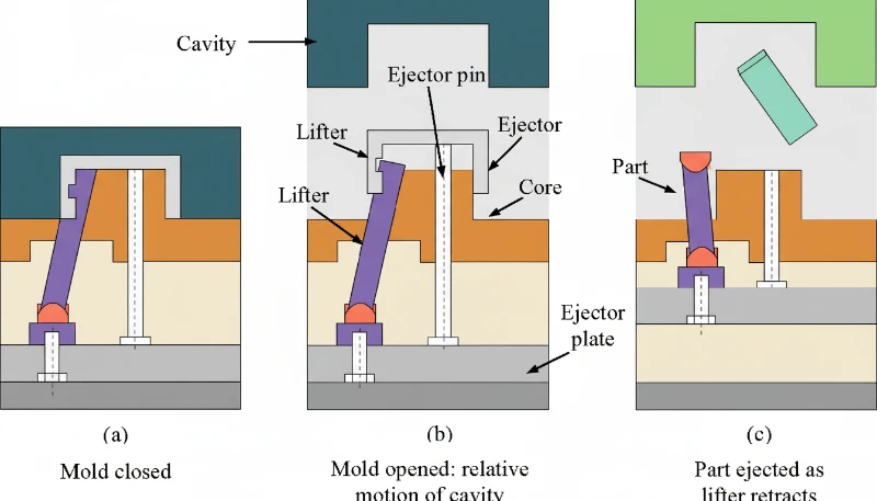
Ejection system selection depends on part geometry. Straight ejection uses ejector pins for simple geometries. Sleeve ejection handles bosses and cylindrical features. Stripper plate ejection works best for thin-wall cups and caps. For undercuts, you need lifters or angled pins. Choosing the wrong system causes part deformation, sticking, or tooling damage that compounds over thousands of cycles.
Ejector pin placement follows specific guidelines. Place pins in thick sections and rib intersections where ejection resistance is highest. Space pins evenly along the part perimeter to distribute force. Pin diameter should be at least 1.5x the pin length to prevent bending. For polished or textured surfaces, avoid placing pins on visible cosmetic areas.
Mold opening speed affects ejection quality. The opening profile: slow initial opening (5-10 mm/s) for first 10-20mm to allow part separation from core without stress. Rapid opening (100-200 mm/s) for the majority of the stroke to minimize cycle time. Deceleration (20-50 mm/s) for final 50-100mm to avoid slamming the mold open and reducing wear on guide pins and bushings. The deceleration is particularly important for molds with stripper plates or complex lifters that need controlled opening sequences.
Step 8: How Do You Inspect Quality and Monitor the Process?
The part is ejected. It lands in the chute or is robotically removed. Now what? If you assume the process is set and let it run, you will discover defects hours or days later when your customer rejects the shipment. Quality inspection must happen at every shift start, after every material change, and at defined intervals during production. The inspection hierarchy: first article inspection (FAI) on startup, in-process inspection every 50-100 parts, final inspection on each shipment lot.
At ZetarMold, our quality workflow covers IQC (incoming quality control), in-process checks with samples, process inspection, packaging inspection, FQC (final quality control), and OQC (outgoing quality control). We have 10+ QC specialists who verify dimensions, surface quality, and functional requirements on every production run. This 6-step workflow, combined with ISO 9001/13485/14001/45001 certifications, ensures consistent quality across our Shanghai factory operations.
Visual inspection catches 60-70% of defects. Burn marks, flash, short shots, sink marks, and surface blemishes are immediately visible. Train operators to inspect critical cosmetic zones first, then structural features. Use backlit inspection stations for transparent parts and polarized light for birefringence detection in optical components.
| Check | Method | Frequency | Acceptance Criteria |
|---|---|---|---|
| Visual Defects | Lightbox inspection | Every 50 parts | No sink >0.2mm in A-surface |
| Dimensions | CMM/caliper | Every 100 parts | ±0.1mm for ±0.05mm tolerance |
| Peso | Scale | Every 25 parts | ±2% of target weight |
| Fit/Function | Assembly test | Come si calcola la forza di clamp per lo stampaggio a iniezione? | No interference or binding |
| Cosmetic | Golden sample | Every part | Match appearance reference |
Dimensional inspection verifies parts meet print requirements. Critical dimensions use CMM (coordinate measuring machine) measurement with ±0.01mm accuracy. Standard dimensions get caliper or go/no-go gauge checks. Sample 5 parts per 100-shot cycle for statistical process control, tracking Cp and Cpk values.
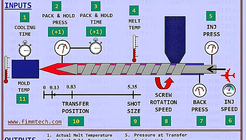
Le macchine moderne monitorano in tempo reale pressione di iniezione, pressione di compattazione, temperatura del fuso, temperatura dello stampo, tempo ciclo e tempo di recupero della vite. Allarmi a ±10–20% dei valori target attivano pause automatiche, separano i pezzi interessati e avvisano gli operatori—intercettando la deriva del processo prima che si accumulino pezzi fuori specifica.
What Are Common Injection Molding Issues and How Do You Troubleshoot Them?
Difetti comuni dello stampaggio a iniezione—affossamenti, sbavature e mancati riempimenti—appaiono anche in processi ben regolati. Ecco le cause radice e le soluzioni.
Sink marks occur when thick sections cool slower than adjacent thin sections, creating surface depressions. The root cause is differential shrinkage. Troubleshooting path: first check wall thickness ratio—if it exceeds 3:1, redesign is required. If wall thickness is acceptable, increase packing pressure in 10% increments while monitoring for flash. Add baffles or bubblers to cool thick sections faster. Reduce melt temperature 5-10°C to minimize initial shrinkage. In severe cases, add external core-outs or gas-assisted molding to eliminate thick sections entirely.
Flash appears at the parting line, around ejector pins, or in vent gaps when material escapes the cavity under excessive injection or packing pressure. Contributing factors include worn mold surfaces, insufficient clamp force, and high melt temperatures that reduce viscosity. Fix flash by increasing clamp force first, then reducing packing pressure, and finally checking mold surface alignment if the problem persists across multiple cavities.
Short shots occur when the cavity is not completely filled, leaving incomplete parts. Common causes include insufficient injection pressure, blocked vents preventing air escape, low melt temperature increasing viscosity, or inadequate shot size. Diagnose by checking injection pressure curves first—most short shots resolve by raising injection speed or pressure by 10-15%. If venting is the issue, clean or deepen vent channels to 0.01-0.02mm depth.
When Should You Adjust vs. Redesign Your Injection Molding Process?
Passare alla riprogettazione quando tre o più modifiche dei parametri di ±20% falliscono, o quando le cause radice includono rapporti di spessore superiori a 3:1 o angoli di sformo inadeguati. La regola empirica: se hai regolato tre parametri di ±20% e il difetto persiste, il problema è probabilmente legato al design. Continuare a regolare oltre questo punto spreca materiale e tempo ciclo senza risolvere il problema.
“Wall thickness ratio >3:1 requires design modification.”Vero
When wall thickness exceeds 3:1 ratio, process adjustments cannot eliminate sink marks and warpage. Core-outs, rib redesign, or gas-assisted molding are necessary design solutions.
“All short shots require mold redesign.”Falso
Short shots caused by venting issues, material contamination, or improper drying can be fixed through process changes. Only short shots caused by flow length limitations or trapped air in geometry require mold modification.
Design issues that resist process adjustment fall into five categories: wall thickness non-uniformity (causes sink and warp), inadequate draft angles (causes sticking), incorrect gate type or location (causes flow lines and weld lines), insufficient coring (wastes material and cycle time), and sharp corners without fillets (creates stress concentrators). Each of these requires a mold modification, not a parameter tweak.
Riprogettare costa 5.000–15.000 USD per ingegnerizzazione, modifica e rivalidazione, ma produrre pezzi difettosi con tassi di scarto del 5–15% su una produzione di 100.000 pezzi costa molto di più.
How Do You Optimize Injection Molding for Production Efficiency?
Puntare prima al raffreddamento—che domina il 60–80% di ogni ciclo—tramite canali conformi e flusso turbolento, quindi minimizzare i tempi di compattazione ed espulsione. Il tempo di ciclo è la somma del tempo di iniezione (5–10%), tempo di compattazione e mantenimento (10–20%), tempo di raffreddamento (60–80%), tempo di apertura e chiusura dello stampo (5–10%) e tempo di espulsione (2–5%). Il raffreddamento è il fattore dominante, quindi l'ottimizzazione dovrebbe concentrarsi prima lì, poi passare agli altri componenti.
ZetarMold gestisce 47 macchine per stampaggio a iniezione da 90T a 1850T e abbiamo ottimizzato il raffreddamento su oltre 100 stampi solo nell'ultimo anno. Implementando raffreddamento conforme, ottimizzando il flusso del refrigerante e riprogettando i punti di iniezione, abbiamo ridotto i tempi ciclo del 15-30% su più linee di produzione. Questi miglioramenti, combinati con la nostra esperienza ventennale dal 2005, ci permettono di offrire prezzi competitivi mantenendo la qualità.
Cooling optimization targets three areas: channel placement, coolant parameters, and mold material selection. Conformal cooling channels follow the part contour, reducing distance to the cavity surface from 15-25mm (drilled) to 3-8mm (conformal). Coolant flow rate must maintain turbulent flow (Reynolds number above 5,000) for effective heat transfer. Mold materials with higher thermal conductivity like beryllium copper inserts in hot spots can cut local cooling time by 30-40%.
Injection optimization focuses on fill time and melt quality. Fill time optimization: reduce injection time until you see burn marks (too fast) or short shots (too slow), then back off 10%. Velocity-to-pressure switchover point should trigger at 95-98% fill to avoid overshooting. Melt temperature profiling across barrel zones prevents degradation while ensuring complete melting.
| Componente | Typical % of Cycle | Optimization Potential | ROI Timeline |
|---|---|---|---|
| Raffreddamento | 60-80% | 15-30% | 500-2000 parts |
| Packing/Holding | 10-20% | 10-20% | Immediate |
| Mold Open/Close | 5-10% | 5-15% | Immediate |
| Iniezione | 5-10% | 5-10% | 100-500 parts |
| Espulsione | 2-5% | 5-10% | 1000-5000 parts |
Il ROI dipende dal valore del pezzo e dal volume. Il recupero dell'investimento sotto 1.000 pezzi dovrebbe essere implementato immediatamente; 1.000–5.000 pezzi richiede valutazione; oltre 5.000 pezzi richiede giustificazione strategica.
Domande Frequenti sul Processo di Stampa a Iniezione
Domande frequenti
What are the 7 steps of injection molding?
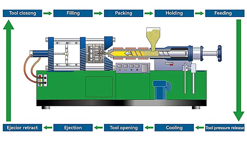
The seven steps of injection molding are: (1) clamping and mold closing, where the machine secures the two mold halves together under high pressure; (2) plastic melting and injection, where heated pellets become molten and are forced into the cavity; (3) packing and holding, where additional material compensates for shrinkage; (4) cooling and solidification, where the part hardens inside the mold; (5) mold opening and part ejection, where the finished part is removed; (6) quality inspection, which covers visual, dimensional, and functional checks; and (7) process monitoring and adjustment, ensuring consistent output throughout production runs.
How long does an injection molding cycle take?
Cycle time ranges from as short as 5 seconds for small thin-wall parts to over 120 seconds for large, thick-wall components. For a typical engineering plastic part with 3mm wall thickness, expect 15-25 seconds per cycle. Cooling dominates the timeline, accounting for 60-80% of total cycle time, while injection fills the cavity in just 0.5-2 seconds. Reducing cooling time through conformal channels or optimized coolant flow is the single most effective way to increase throughput, often cutting cycle time by 20-35% on existing molds.
What is the difference between injection and packing?
Injection is the high-pressure fill phase where molten plastic is forced into the mold cavity at speeds designed to fill 95-98% of the volume, typically completing in 0.5-2 seconds. Packing (or holding) follows immediately at lower pressure, pushing additional material into the cavity to compensate for thermal shrinkage as the plastic cools and contracts. Packing continues until the gate freezes off, usually 2-6 seconds. Think of injection as getting the material into the mold, and packing as keeping it dimensionally accurate as it solidifies.
Why do I need to dry plastic before injection molding?
Hygroscopic materials such as PA6, PC, PET, and PEEK absorb moisture from ambient air over time. During injection molding, this trapped moisture vaporizes instantly at melt temperatures (often above 250°C), causing visible bubbles (splay marks), surface streaks, reduced mechanical strength, and dimensional instability in the finished part. Proper drying at material-specific temperatures (80-160°C) for 3-6 hours reduces moisture content below the critical 0.02% threshold required for defect-free molding. Skipping the drying step remains one of the most common and costly causes of rejected parts in production.
What temperature is used for injection molding?
Injection molding temperatures vary significantly by material type. Polypropylene processes at 180-220°C, ABS at 210-250°C, polycarbonate at 280-320°C, and high-performance PEEK requires 380-420°C. The barrel maintains a temperature gradient from the feed zone (coolest) through compression to the metering zone (hottest), typically with a 20-40°C rise. Mold temperature also plays a critical role: colder molds speed up cycle time but can increase residual stress, while heated molds (60-150°C depending on resin) improve surface finish, crystallinity, and dimensional stability for engineering-grade materials.
How much pressure is needed for injection molding?
Injection pressure typically ranges from 18,000 to 25,000 psi for standard engineering thermoplastics. High-viscosity or glass-filled materials like PEEK or PA66-GF30 can require up to 35,000-50,000 psi. Packing pressure runs at 50-80% of injection pressure. To determine required clamp force, multiply the projected part area (in square inches) by injection pressure, then add a 20-30% safety margin. For example, a 10 square inch part at 18,000 psi needs roughly 90 tons of clamp force, so a 110-115 ton machine provides adequate headroom.
What causes sink marks in injection molding?
Sink marks form when thick wall sections cool more slowly than adjacent thin sections, creating differential shrinkage that physically pulls the surface material inward. The primary causes include wall thickness ratios exceeding 3:1, insufficient packing pressure or hold time, and inadequate cooling channel placement near heavy cross-sections. Practical fixes include coring out thick sections during the DFM stage, increasing packing pressure and extending hold time until gate freeze, and redesigning cooling channels to target thick areas. Process adjustments can resolve mild cases, but severe recurring sinks usually require a mold modification.
How do you calculate clamp force for injection molding?
Padroneggia il processo di stampaggio a iniezione passo dopo passo: dalla revisione DFM attraverso la serraggio, iniezione, compattazione, raffreddamento ed espulsione fino al controllo qualità.
-
pressione di iniezione: La pressione di iniezione si riferisce alla pressione idraulica applicata alla vite per forzare la plastica fusa nella cavità dello stampo, tipicamente compresa tra 35.000 e 50.000 psi. ↩
-
clamp force: La forza di chiusura è la forza idraulica o meccanica che mantiene lo stampo chiuso durante l'iniezione, misurata in tonnellate, con intervalli comuni da 90T a 1850T. ↩
-
tempo di ciclo: Il tempo di ciclo è la durata totale necessaria per completare un ciclo di stampaggio a iniezione, misurata in secondi, dalla chiusura dello stampo all'inizio del ciclo successivo. ↩


