 Przejdź do treści

Designing an forma wtryskowa involves several key steps like material selection, cavity layout, and part geometry considerations for optimal results and high production efficiency.
Understanding mold design principles is essential for efficient production and high-quality output. Whether you are designing a new mold or optimizing an existing tool, these factors directly influence mold performance, cycle time, and overall cost savings for manufacturers.
- Mold material choice (steel vs aluminum) directly impacts tool life and part quality
- Proper cooling channel layout can reduce cycle time by up to 70%
- Uniform wall thickness is the single most critical design factor
- Vent groove depth of 0.01–0.03 mm prevents flash while allowing gas escape
- Regular mold maintenance extends tool life and maintains dimensional accuracy
Jakie są podstawowe zasady działania form wtryskowych?
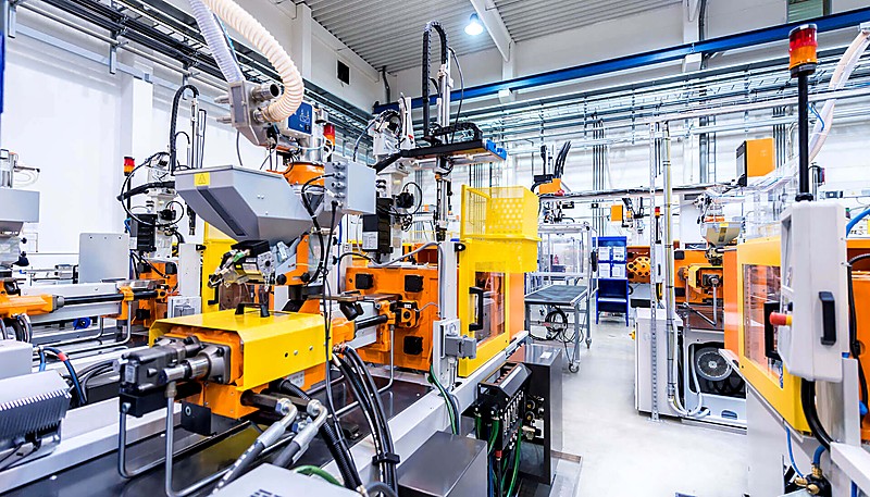
Formy wtryskowe są niezbędne do produkcji części o wysokiej precyzji, wykorzystując proces, w którym stopiony materiał jest wtryskiwany do gniazda formy. Technologia ta stanowi podstawę wielu gałęzi przemysłu, zapewniając szybką i spójną produkcję.
If you are comparing vendors or planning procurement, our injection molding supplier sourcing guide covers RFQ prep, qualification, and commercial risk checks.
Proces formowania wtryskowego injects molten material into a mold cavity under high pressure, where it solidifies to form the desired product. Mold design ensures the product can be easily removed and closely matches the expected dimensions.

The materials, structure, and layout of injection molds directly relate to the quality, efficiency, and cost of the final product.
Podstawowe zasady projektowania form wtryskowych obejmują kilka kluczowych etapów
Preparation of molten plastic is the first stage. The plastic raw material is melted by the shearing action of the screw and the heater.
Injection: The molten plastic is forced into the mold cavity through the nozzle with help of pressure exerted by the screw.
With over 20 years of injection mold design experience, ZetarMold operates 47 injection molding machines (90T–1850T) at our Shanghai factory, handling mold designs for parts of virtually any size and complexity.
Holding Pressure and Cooling: The injection molding machine keeps this pressure for some time to ensure that the cavity is filled and then starts cooling process as the plastic starts to set.
After the plastic solidifies, the mold opens and the ejection system — typically pins, plates, or sleeves — pushes the finished part out of the cavity. Proper ejection design ensures the part releases cleanly without deformation or damage to critical surfaces.
“Proper mold design reduces defects and improves production efficiency.”Prawda
Well-designed injection molds achieve consistent part quality, lower scrap rates, and shorter cycle times across production runs.
“Injection mold design is only about the product shape.”Fałsz
Mold design also includes material selection, cooling system layout, ejection mechanisms, and process optimization for efficient production.
Jakie są materiały form?
Mold materials are essential in manufacturing processes like injection molding, ensuring durability, precision, and quality. The choice of material affects production efficiency and the final product’s characteristics.
Wybór materiału formy ma ogromny wpływ na żywotność formy i jakość gotowego produktu. Powszechnie stosowanymi materiałami są stal i aluminium.
Stal
Steel molds offer superior hardness, wear resistance, and heat treatment properties with significantly longer working life than aluminum — ideal for high-volume production where dimensional consistency is critical.
The main drawbacks of steel molds are longer machining times and higher material costs compared to aluminum. Steel is also significantly heavier, which increases handling difficulty and wear on mold-change equipment. However, the longer tool life usually offsets these disadvantages in high-volume applications.
Stale zwykłe:
Stal P201 is a versatile pre-hardened mold steel (28–36 HRC) widely used for mold bases and large cavities. It offers excellent machinability and polishability at a cost-effective price point for medium-volume production molds.
H13 is a hot-work tool steel for molds operating at elevated temperatures. It maintains hardness and thermal stability after prolonged heat exposure, with typical hardness of 44–52 HRC after treatment.
S136 is a stainless tool steel with excellent corrosion resistance and polishability. It is the preferred choice for optical lenses, transparent parts, and medical molds where surface finish quality is paramount.
Aluminium
Aluminum molds offer significant weight savings and roughly 4–5x better thermal conductivity than steel, enabling faster cooling and shorter cycle times. Easy machinability reduces tooling lead time and cost, making aluminum ideal for prototyping and low-volume production.
The main drawback is lower hardness and wear resistance, making aluminum molds susceptible to surface damage with abrasive resins. Best suited for production runs under 10,000–50,000 parts where tooling speed matters more than longevity.
Aluminium zwykłe:
7075 is one of the strongest aluminum grades (tensile strength ~570 MPa). Despite this, its hardness remains far below tool steel, making it best suited for prototype molds and short production runs.
Co głównie obejmuje projektowanie struktury formy?
Projektowanie struktury formy jest kluczem do tworzenia wysokiej jakości form wtryskowych, zapewniając wydajność i spójność podczas procesu formowania. Wiąże się to z krytycznymi aspektami, takimi jak przepływ w formie, chłodzenie i kompatybilność materiałowa.
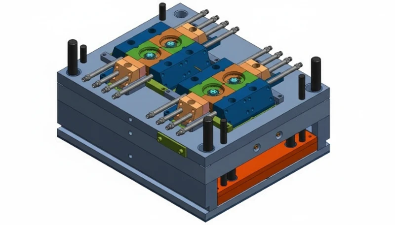
Mold structure design refers to the cavity, core, frame, gate, guide, and withdrawal system. All must be carefully engineered for proper efficiency, sturdiness, and easy maintenance.
Wnęka i rdzeń
Wnęka tworzy zewnętrzne wymiary produktu, podczas gdy rdzeń zapewnia wewnętrzne wymiary połączone ze sobą, aby zapewnić ostateczny i pożądany kształt i rozmiar produktu.
Material Selection: Often employ high-hardness, wear-resistant steel, such as P20 or H13 steel.
Design Points: The finished surfaces of cavity & core should be smooth so that high dimensional accuracy should be maintained for the surface finish of the product.
Podstawa formy
Podstawa formy jest również szkieletem narzędzia i ma za zadanie mocowanie i łączenie wszystkich komponentów. Zazwyczaj ma ona standardowy kształt umożliwiający montaż form i ich wymianę w razie potrzeby.
Material Selection: Usually, 45 steel or Q235 steel is adopted for the mold base to guarantee the stability of the mold base.
At ZetarMold, our in-house mold manufacturing facility produces over 100 mold sets per month using UG, SOLIDWORKS, MOLDFLOW, and CAD to simulate mold flow and validate cooling designs before machining begins.
“Mold structure design directly impacts part quality and production efficiency.”Prawda
Proper cavity layout, cooling channel placement, and ejection system design determine dimensional accuracy, cycle time, and defect rates.
“All mold structures are the same regardless of the application.”Fałsz
Mold structures vary significantly depending on part geometry, material properties, production volume, and industry-specific requirements.
Design Points: The mold base should possess enough robustness and sturdiness to be able to cope with injection pressure, injection temperature and the general to and fro pressure during injection.
System bramek

System wlewowy składa się z prowadnicy głównej, prowadnic pomocniczych i wlewów, za pomocą których roztopione tworzywo sztuczne jest wprowadzane do gniazda. Skuteczny system wlewowy jest pomocny w zwiększaniu jakości formowania i zmniejszaniu ilości zużywanego materiału.
Design Points: The main runner should be as short and as straight as can be in order to minimize the pressure loss as well as cuts as much as is possible.
Design Points: Sub-runners should be properly arranged so that it would apply equal mass to the cavity.
Design Points: The nature of the gate should not in any way influence the look of the product or compromise on its strength The size of the gate used should be good.
Mechanizm przewodni
Mechanizm prowadzący obejmuje sworznie prowadzące i tuleje, które pomagają w wyrównaniu ruchomych i nieruchomych form.
Material Selection: Typically uses high-hardness steel, such as GCr15.
Design Points: The guiding mechanism should be very accurate in term of the alignment to prevent misalignment over a long period of time besides being very resistant to wear.
Mechanizm wyrzucania
Część wypychająca jest stosowana do wyjmowania uformowanego produktu z formy i zwykle stosuje się kołki wypychające, płyty i tuleje.
Design Points: Another requirement of this force is that it should be constant or smooth since a sudden force may affect the product in a negative way. The movement of the ejection mechanism should also be smooth to avoid sticking.
Czym jest projektowanie kanałów przepływu?
Flow channel design is the engineering of the sprue, runners, and gates that guide molten plastic from the machine nozzle into the mold cavity.
Runner design significantly influences product quality and production efficiency. The size and shape of the runner must match the material and part geometry.
Główny biegacz
Główny kanał łączy dyszę wtryskarki z kanałami podrzędnymi i powinien być możliwie najkrótszy i prosty, aby zmniejszyć straty ciśnienia i straty materiału.
Design Points: The main runner diameter should be right to promote adequate flow all the same reduce wasteful use of the materials.
Podbiegi
Prowadnice pomocnicze rozprowadzają stopiony plastik do każdej wnęki formy, a równowaga powinna być tutaj głównym czynnikiem.
Design Points: Sub-runner cross-sectional shapes should be best circular or semicircular to lower the resistance offered by flows. The length should ideally be as equal as possible, so that the cavity filling time is almost equal for all the lengths.
Bramki
Bramy są środkiem, za pomocą którego stopione tworzywo sztuczne wprowadzane do wnęki wpływa na jakość produktu.
Design Points: The gates should be placed in areas that do not affect appearance or strength. Their sizes must provide adequate fill rates while being easy to remove. Different gate types serve different product requirements.
Dodatkowo, projekt runnera powinien uwzględniać:
Równowaga kanałów doprowadzających: W przypadku wielu gniazd upewnij się, że długości kanałów i ich pole przekroju poprzecznego są odpowiednie, ponieważ są one głównym czynnikiem decydującym o czasie wypełnienia form.
Chłodzenie kanałów doprowadzających: Wystarczające zapewnienie kanały chłodzące2 dla sekcji kanału doprowadzającego, aby wysoka temperatura nie wpływała na przepływ stopu.
Precyzja kanału: Wysoka precyzja obróbki i gładka powierzchnia, aby zmniejszyć opór przepływu stopu i spadek ciśnienia.
Czym jest konstrukcja układu chłodzenia?
Projekt systemu chłodzenia ma kluczowe znaczenie dla optymalizacji procesów produkcyjnych, zapewniając stałą jakość produktu i wydajność w cyklach produkcyjnych.
„Projekt kanału przepływowego znacząco wpływa na wydajność formowania i jakość części.”Prawda
Zoptymalizowana geometria kanałów doprowadzających i bramek redukuje odpad materiałowy, skraca czas cyklu i poprawia spójność wypełnienia we wszystkich gniazdach.
„Projekt kanału przepływowego jest identyczny dla wszystkich typów form i materiałów.”Fałsz
Geometria kanału przepływowego musi być dostosowana na podstawie lepkości materiału, grubości części, typu bramki i układu wnęki dla optymalnych wzorów napełniania.
Układ chłodzenia odgrywa bardzo ważną rolę w projektowaniu form wtryskowych, ponieważ skraca czas cyklu formowania wtryskowego i obniża jakość formy. System chłodzenia obejmuje głównie kanały chłodzące i etapy czasu chłodzenia.
Kanały chłodzące
Kanały chłodzące prowadzą wodę chłodzącą przez różne części formy w celu usunięcia nadmiaru ciepła.
Kanały chłodzące powinny być umieszczone jak najbliżej powierzchni wnęki, aby zmaksymalizować rozpraszanie ciepła. Odległość kanału od wnęki wynosząca 1,5–2,5 razy średnica kanału równoważy wydajność chłodzenia z integralnością strukturalną stali formy.
Przepływ chłodziwa powinien być równomiernie rozłożony na wszystkich kanałach, aby zapobiec lokalnym gorącym punktom. Nierównomierne chłodzenie prowadzi do różnicowego kurczenia się, naprężeń wewnętrznych i odkształceń w gotowej części. Przegrody lub wkłady spiralne mogą pomóc w przekierowaniu przepływu do niedostatecznie obsługiwanych obszarów formy.
Średnica kanału musi być wystarczająco duża, aby utrzymać odpowiednią prędkość przepływu chłodziwa — zazwyczaj 1,5–3 m/s — bez tworzenia nadmiernego spadku ciśnienia. Zbyt małe średnice niosą ryzyko zablokowania przez osad lub zanieczyszczenia, podczas gdy zbyt duże kanały zmniejszają turbulencje przepływu i efektywność wymiany ciepła.
Czas chłodzenia
Czas chłodzenia zależy również od grubości ścianek produktu, rodzaju użytego materiału oraz temperatury formy.
Wystarczający czas chłodzenia zapobiega odkształceniom i skurczowi, zapewniając stabilność wymiarową. Optymalny czas równoważy integralność części z wydajnością — zazwyczaj stanowi 60–80% całkowitego czasu cyklu w większości operacji wtryskiwania.
Inne kwestie dotyczące systemów chłodzenia obejmują
Prędkość przepływu chłodziwa wymaga starannej kontroli. Niska prędkość może zmniejszyć efektywność chłodzenia, podczas gdy wysoka może prowadzić do zablokowania i zużycia formy.
Temperatura chłodziwa: Optymalna temperatura, ponieważ wysoka temperatura zmniejsza szybkość chłodzenia, podczas gdy niska temperatura spowoduje kondensację na powierzchni formy i może wpłynąć na jakość produktu.
Jakość chłodziwa: Utrzymuj chłodziwo w czystości, aby uniknąć zatorów i uszkodzeń formy.
Czym jest konstrukcja układu wydechowego?
Projekt systemu odpowietrzania to inżynieria rowków i otworów odpowietrzających, które pozwalają uwięzionemu powietrzu i gazom uciec z wnęki formy podczas wtrysku.
System odpowietrzania usuwa gaz z wnęki formy, aby zapobiec wadom, takim jak pęcherzyki i oparzenia, bezpośrednio wpływając na jakość produktu i trwałość formy.
Rowki wentylacyjne
Odprowadzenie rowek3 jest kanałem do ucieczki gazu i znajduje się głównie w linii podziału.
Punkty projektowe: Umieszczaj rowki lokalizacyjne tam/gdzie gaz może swobodnie się gromadzić.
Punkty projektowe: Szerokość i głębokość powinny optymalizować pole przekroju poprzecznego dla wymaganego odpowietrzania, tak aby nie było żadnych problemów po stronie wypraszania tworzywa.
Punkty projektowe: Równomierne rozmieszczenie, aby zapobiec lokalnym problemom z odpowietrzaniem.
Otwory wentylacyjne
Otwory wentylacyjne należą do elementów systemu wentylacyjnego, które zwykle znajdują się w cienkich obszarach produktu.
Punkty projektowe: Odpowiednia średnica, aby nie utrudniać uwalniania nagromadzonego gazu, jednocześnie gwarantując właściwe odpowietrzanie.
Punkty projektowe: Pozycjonowanie nie powinno w żaden sposób wpływać na wygląd produktu ani jego wytrzymałość.
Punkty projektowe: Ilość i lokalizacja powinny być rozsądne w odniesieniu do struktury formy i kształtu produktu.
Projekt systemu wentylacji powinien również uwzględniać:
Konserwacja systemu: Powinny być okresowo czyszczone, aby zapewnić swobodny i niezakłócony przepływ, ale należy je czasami sprawdzać, aby uniknąć narzędzi, które mogą powodować zatory prowadzące do problemów z jakością.
Chłodzenie systemu: W przypadku używania form wysokotemperaturowych należy zastosować środki chłodzące, aby uniknąć kondensacji gazów podczas odpowietrzania.
Precyzja przetwarzania: Wysoka precyzja z gładkimi powierzchniami, aby zmniejszyć opór przepływu gazu i straty ciśnienia.
ZetarMold przetwarza ponad 400 materiałów plastikowych. Nasi 8 starszych inżynierów nadzorują jakość przetwarzania form w ramach certyfikowanych systemów zarządzania ISO 9001, ISO 13485, ISO 14001 i ISO 45001.
Na czym polega przetwarzanie form?
Przetwarzanie formy to seria kroków obróbki CNC, EDM, szlifowania i obróbki powierzchniowej, które przekształcają surową stal w precyzyjną formę wtryskową.
„Właściwe przetwarzanie formy zapewnia dokładność wymiarową i jakość powierzchni.”Prawda
Obróbka CNC, EDM i obróbka powierzchniowa elementów formy zapewniają precyzyjne tolerancje i gładkie powierzchnie dla spójnej produkcji części.
„Obróbka formy jest konieczna tylko w przypadku form do produkcji wielkoseryjnej.”Fałsz
Wszystkie formy wymagają odpowiedniej obróbki mechanicznej, obróbki cieplnej i wykończenia powierzchni, niezależnie od wielkości produkcji, aby osiągnąć wymagane tolerancje.
Obróbka formy to proces przekształcania rysunku projektowego w rzeczywistą formę poprzez obróbkę zgrubną, precyzyjną, obróbkę powierzchni itp. Dzięki analizie można zauważyć, że dokładność i jakość obróbki bezpośrednio wpływają na funkcjonalność i trwałość formy.
Obróbka zgrubna
Obróbka zgrubna jest wykonywana na formie z surowca, a powszechnie używanym sprzętem jest frezarka CNC i tokarka.
Kluczowe punkty: Zostaw wystarczający naddatek na wykończenie.
Kluczowe punkty: Optymalna prędkość i posuw pomagają uniknąć deformacji materiału oraz stopniowego zużycia narzędzi i maszyn.
Kluczowe punkty: Obróbka zgrubna w celu zmniejszenia zadziorów i uzyskania gładszej powierzchni.
Wykończenie
Wykończenie jest wykonywane w celu osiągnięcia rozmiaru i specyfikacji formy i wykorzystuje proces szlifowania, EDM i polerowania.
Kluczowe punkty: Dokładność zapewnia, że kształt i rozmiar formy są prawidłowe.
Kluczowe punkty: Unikaj nadmiernego polerowania, aby zapobiec odchyleniom wymiarowym.
Kluczowe punkty: Wykończenie powierzchni najlepszym i najbardziej odpowiednim sprzętem w celu uzyskania gładkiego i właściwego wykończenia.
Obróbka powierzchni
Obróbka powierzchni formy zwiększa twardość formy i odporność na zużycie, w której stosuje się procesy hartowania, azotowania i stosowania powłoki powierzchniowej.
Kluczowe punkty: Wybierz odpowiednie metody obróbki w zależności od materiału formy i zastosowania.
Kluczowe punkty: Aby zmniejszyć deformację i pęknięcia formy, należy kontrolować czas obróbki i temperaturę.
Kluczowe punkty: Dokładnie wyczyść przed obróbką, aby zapewnić lepszą przyczepność i wydajność.
Jak dbać o pleśń?
Właściwa konserwacja form ma kluczowe znaczenie dla zapewnienia stałej jakości i trwałości w formowaniu wtryskowym. Regularna konserwacja może zapobiec przestojom i kosztownym naprawom.
Konserwacja formy, zarówno codzienna, jak i okresowa, wydłuża okres użytkowania i redukuje koszty produkcji poprzez konsekwentną pielęgnację.
Rutynowa konserwacja
Kluczowe punkty: Upewnij się, że powierzchnia formy jest czysta, aby zapobiec przenikaniu temperatur i kurzu do formy.
Kluczowe punkty: Regularnie smaruj słup prowadzący i tuleję prowadzącą, aby zapewnić elastyczność mechanizmu prowadzącego.
Kluczowe punkty: Może być konieczne częste sprawdzanie innych komponentów formy oraz ich naprawa lub wymiana w odpowiednim czasie.
Kluczowe punkty: Konieczne jest potwierdzenie, czy kanał chłodzący i system odpowietrzania są normalnie otwarte i czy nie są zablokowane; jeśli są zablokowane, należy je niezwłocznie oczyścić.
Regularna konserwacja
Konserwacja oznacza ogólną kontrolę i naprawę formy po pewnym czasie jej użytkowania.
Kluczowe punkty: Sprawdź wnękę i rdzeń formy oraz poszukaj części wnęki, która jest poważnie zużyta, i napraw lub wymień je.
Kluczowe punkty: Sprawdź, czy mechanizm prowadzenia, mechanizm odformowania i inne części formy działają normalnie, i dokonaj niezbędnych regulacji lub wymian.
Kluczowe punkty: Sprawdź, czy system chłodzenia formy i system odpowietrzania formy działają prawidłowo i czy istnieje potrzeba ich oczyszczenia oraz udrożnienia.
Kluczowe punkty: Dokładnie wyczyść i nasmaruj formę, aby zapewnić jej prawidłowy stan techniczny.
Jakie są najczęstsze problemy w projektowaniu form i ich rozwiązania?
Typowe problemy z projektowaniem form obejmują słabe chłodzenie, nierówny przepływ materiału oraz nieprawidłowe umieszczenie bramy, co wpływa na jakość detalu.
„Regularne czyszczenie wydłuża żywotność formy i utrzymuje jakość części.”Prawda
Planowana konserwacja, obejmująca czyszczenie, smarowanie i kontrolę, zapobiega zużyciu, korozji i dryfowi wymiarowemu w cyklach produkcyjnych.
"Konserwacja formy jest zbędna, jeśli forma jest prawidłowo zaprojektowana."Fałsz
Wszystkie formy wymagają regularnego czyszczenia i kontroli, niezależnie od jakości projektu, aby utrzymać dokładność wymiarową i zapobiec postępującemu zużyciu.
Kilka typowych problemów może wpływać na jakość detalu i szybkość produkcji, jeśli nie zostaną właściwie rozwiązane podczas projektowania formy.
Znaki zlewu
Opis problemu: Powierzchnia produktu jest wklęsła, co wpływa na jego wygląd.
Rozwiązanie: Zaleca się, aby pozycja oraz rozmiar bramki były takie, aby mogła ona pomieścić stop i równomiernie wypełnić wnękę.
Rozwiązanie: Zmaksymalizuj projekt i rozmieszczenie obwodu chłodzenia, aby zapewnić równomierny rozkład chłodzenia wyrobów.
Rozwiązanie: Dostosuj czas docisku i ciśnienie, aby zmniejszyć skurcz stopu.
Flash
Opis problemu: Odcinki tworzą się na obwodzie wyrobu, pogarszając jego wygląd i mogąc wpływać na niedokładność wymiarów.
Rozwiązanie: W odniesieniu do projektu powierzchni podziałowej formy, staraj się, aby forma była zamknięta do minimum.
Rozwiązanie: Zwiększ siłę docisku formy, aby zapobiec jej rozdzieleniu podczas procesu produkcyjnego wtrysku.
Rozwiązanie: Aby sprawdzić formę, najpierw należy sprawdzić mechanizm prowadzenia formy oraz mechanizm dociskania formy.
Bańka
Opis problemu: Na powierzchni wyrobu lub wewnątrz niego widoczne są pory w postaci pęcherzy, które wpływają na wygląd i trwałość.
Rozwiązanie: Zmniejsz projekt systemu odpowietrzania, aby umożliwić skuteczne usuwanie gazu z gniazda formy.
Rozwiązanie: Dostosować parametry wtrysku, takie jak prędkość wtrysku, siła wtrysku i temperatura materiałów do wtrysku, aby zminimalizować powstawanie gazów.
Rozwiązanie: Sprawdź suszenie surowców, aby zapewnić, że zawartość wilgoci w surowcach jest na odpowiednim poziomie.
Odkształcenie i wypaczenie
Opis problemu: Wtryskiwana część częściowo się kurczy lub odkształca po schłodzeniu, a stabilność wymiarowa i wykończenie powierzchni produktu są zagrożone.
Rozwiązanie: Ulepszyć system chłodzenia, aby zapewnić wszystkim wtryskiwanym częściom jak najbardziej równomierne temperatury.
Rozwiązanie: Dostosuj czas docisku i ciśnienie docisku ustawione w parametrach wtrysku, aby zmniejszyć naprężenia wewnętrzne.
Rozwiązanie: Wzmocnij zmiany w projekcie konstrukcji formy, takie jak dodanie żeber wzmacniających, aby produkt miał równomierną grubość ścianki i spójną grubość ścianki.

Niestabilność wymiarowa
Opis problemu: Geometria jest niezgodna z wymaganymi wymiarami i normami, co wpływa na montaż i użytkowanie produktu.
Rozwiązanie: Sprawdź poprawność obróbki formy i realizacji montażu produktów, aby zweryfikować, czy wymiary formy są zgodne ze specyfikacjami projektowymi wtryskiwania.
Rozwiązanie: Kontrolować parametry procesu, takie jak ciśnienie wtrysku, czas docisku i czas chłodzenia, aby zapewnić stabilne wymiary produktu.
Rozwiązanie: Potwierdź stabilność produkcyjną maszyn do wtryskiwania tworzyw sztucznych, aby mieć możliwość określenia zmienności procesu wtryskiwania.
Często zadawane pytania
Jaki jest najważniejszy czynnik w projektowaniu form wtryskowych?
Najbardziej krytycznym czynnikiem w projektowaniu form wtryskowych jest osiągnięcie jednolitej grubości ścianki w całym detalu. Nierówne ścianki powodują różnicowe chłodzenie, co bezpośrednio prowadzi do wgnieceń, odkształceń i braku stabilności wymiarowej gotowego wyrobu. Z naszego doświadczenia w ZetarMold, wynikającego z pracy z ponad 400 materiałami, detale z różnicami grubości ścian przekraczającymi 15 procent prawie zawsze wymagają kosztownej przeróbki formy, aby osiągnąć akceptowalną jakość. Oprócz grubości ścianki, prawidłowe umiejscowienie bramy i wydajny układ systemu chłodzenia są równie ważne dla określenia czasu cyklu i długotrwałej trwałości formy.
Ile czasu zajmuje zaprojektowanie formy wtryskowej?
Typowe projektowanie formy wtryskowej trwa od 2 do 4 tygodni w zależności od złożoności części. Proste formy jednogniazdowe dla nieskomplikowanych geometrii mogą zająć zaledwie 5 do 7 dni od koncepcji do gotowych rysunków. Złożone formy wielogniazdowe z bocznymi wypychaczami, podnośnikami lub mechanizmami odkręcającymi mogą wymagać od 4 do 6 tygodni pracy inżynierskiej. Faza projektowania obejmuje modelowanie 3D CAD, symulację przepływu w formie w celu walidacji wzorców napełniania oraz wielokrotne iteracje przeglądu projektu. W ZetarMold nasi 8 starszych inżynierów stosuje ustrukturyzowany proces przeglądu, który pozwala wcześnie wychwycić problemy.
Jakiego oprogramowania używa się do projektowania form wtryskowych?
Oprogramowanie będące standardem branżowym w projektowaniu form wtryskowych obejmuje SOLIDWORKS i UG, znane również jako NX, do modelowania 3D CAD oraz Autodesk Moldflow do symulacji przepływu i analizy termicznej. Te narzędzia pozwalają inżynierom wizualizować układ wnęki, symulować wzory napełniania tworzywem sztucznym i optymalizować rozmieszczenie kanałów chłodzących, zanim zostanie przecięta jakakolwiek stal. W ZetarMold nasz zespół projektowy wykorzystuje połączenie SOLIDWORKS, MOLDFLOW i CAD do walidacji rozmieszczenia bramek, przewidywania pozycji linii zgrzewu oraz analizy wydajności chłodzenia, co pozwala zmniejszyć wady pierwszych sztuk nawet o 60 procent w porównaniu z tradycyjnymi metodami prób i błędów.
What is the typical cost of an injection mold?
Koszty form wtryskowych wahają się znacznie w zależności od złożoności i wymagań produkcyjnych. Proste prototypowe formy aluminiowe jednogniazdowe zaczynają się od około 1000 do 3000 dolarów, podczas gdy formy stalowe klasy produkcyjnej z wieloma gniazdami i systemami gorących kanałów zazwyczaj kosztują od 10 000 do 50 000 dolarów. Wysoce złożone formy z bocznymi wypychaczami, odkręcanymi rdzeniami lub specjalistycznymi wykończeniami powierzchni mogą przekraczać 100 000 dolarów. Kluczowymi czynnikami kosztów są liczba gniazd, wybór materiału formy, oczekiwana wielkość produkcji, wymagana jakość wykończenia powierzchni oraz specyfikacje tolerancji dla aplikacji.
Jak zapobiegać wypływowi w projektowaniu form wtryskowych?
Zapobieganie wypływu zaczyna się od precyzyjnego zaprojektowania powierzchni rozdzielającej formy i prawidłowego obliczenia siły docisku. Linia rozdzielająca formy musi być obrobiona z tolerancją płaskości w granicach 0,01 milimetra, aby zapewnić pełne zamknięcie pod ciśnieniem wtrysku. Rowki odpowietrzające powinny być prawidłowo wymiarowane na głębokość od 0,01 do 0,03 milimetra, aby uwięzione gazy mogły się wydostać, nie pozwalając jednocześnie na wyciek stopionego materiału. Maszyna do wtrysku tworzyw sztucznych musi posiadać wystarczającą siłę docisku (tonaż). W ZetarMold nasze 47 pras obejmuje zakres od 90T do 1850T, co pozwala na precyzyjne dopasowanie wydajności maszyny do każdej formy.
Jaka jest różnica między formą z zimnym a gorącym kanałem?
Forma z zimnym kanałem doprowadza stopiony plastik przez nieogrzewane kanały, co skutkuje zestalonym odpadem kanałowym, który musi zostać oddzielony, przetworzony i poddany recyklingowi lub wyrzucony. Forma z gorącym kanałem wykorzystuje elektrycznie ogrzewane systemy rozdzielaczy, aby utrzymać plastik w stanie stopionym w kanałach dystrybucyjnych, całkowicie eliminując odpady kanałowe i skracając czas cyklu. Formy z gorącym kanałem są początkowo droższe o 20 do 40 procent ze względu na ogrzewany rozdzielacz i kontrolery temperatury, ale przy dużych nakładach produkcyjnych pozwalają zaoszczędzić 15 do 30 procent kosztów materiałów i poprawiają powtarzalność.
Jaką tolerancję można osiągnąć w procesie wtryskiwania tworzyw sztucznych?
Standardowe wtryskiwanie osiąga tolerancje plus minus 0,1 milimetra dla wymiarów poniżej 25 milimetrów. Precyzyjne wtryskiwanie z optymalizacją sterowania procesem, ścisłą regulacją temperatury i wysokiej jakości narzędziami może osiągnąć tolerancje plus minus 0,05 milimetra lub mniejsze dla krytycznych cech. Zdolność tolerancyjna w dużej mierze zależy od właściwości kurczliwości materiału, przy czym materiały półkrystaliczne wykazują większą zmienność niż amorficzne. W przypadku zastosowań wymagających ciasnych tolerancji inżynierowie ZetarMold wykorzystują symulację Moldflow podczas fazy projektowej, aby przewidzieć i skompensować skurcz przed wykonaniem formy.
Why Does Injection Mold Design Matter for Manufacturing Success?
Projekt formy wtryskowej jest najważniejszym czynnikiem dla jakości części, wydajności produkcji i kontroli kosztów w przetwórstwie tworzyw sztucznych.
Ten artykuł dostarcza praktycznych odniesień dla projektantów form wtryskowych. W celu uzyskania wsparcia w projektowaniu form na zamówienie skontaktuj się z ZetarMold po fachową pomoc.
Dowiedz się o wtrysku tworzyw sztucznych: Kompleksowy przewodnik: Wtryskiwanie tworzyw sztucznych to proces wytwórczy, w którym stopiony plastik jest wtryskiwany do formy w celu tworzenia detali o wysokiej dokładności i powtarzalności. ↩
Dowiedz się, co to jest rdzeń i gniazdo w wtrysku tworzyw sztucznych? Gniazdo i rdzeń w typowej maszynie do wtrysku tworzyw sztucznych są elementami formującymi formy. ↩
Dowiedz się o typach bramek do wtryskiwania tworzyw sztucznych: Kompletny przewodnik projektowy: Bramka wtryskowa to zaprojektowany otwór, zazwyczaj mały, który kontroluje przepływ stopionego tworzywa do wnęki formy. ↩
Dowiedz się o stali narzędziowej H13: H13 to stal narzędziowa do pracy na gorąco o dobrej odporności na zmęczenie cieplne, erozję i zużycie, szeroko stosowana do wyrobu form i tłoczników. ↩
Dowiedz się o czterech ważnych zasadach, które należy wziąć pod uwagę przy projektowaniu grubości ścianki: Grubość ścianki wyrobu z tworzywa sztucznego jest kluczową cechą konstrukcyjną, często omawianą i braną pod uwagę przy projektowaniu konstrukcji wyrobów z tworzyw sztucznych. ↩
Dowiedz się, jak określić ciśnienie docisku i czas docisku w procesie wtryskiwania tworzyw sztucznych? Ciśnienie wtrysku obejmuje zarówno ciśnienie, jak i prędkość. ↩
Get competitive pricing, DFM feedback, and production timeline from ZetarMold’s engineering team.
Request a Free Quote →
-
Stal P20: Stal P20 odnosi się do normy ASTM A681, która określa stopy stali narzędziowej, w tym P20, o typowej twardości 28-36 HRC do zastosowań w podstawach form ↩
-
kanały chłodzące: kanały chłodzące mogą stanowić do 70% całkowitego czasu cyklu wtryskiwania według badań inżynierii polimerów ↩
-
rowek: rowek odnosi się do standardowej głębokości rowka odpowietrzającego, która wynosi od 0,01 do 0,03 mm dla większości tworzyw termoplastycznych, aby umożliwić ucieczkę gazu bez wypływu ↩


