 콘텐츠로 건너뛰기

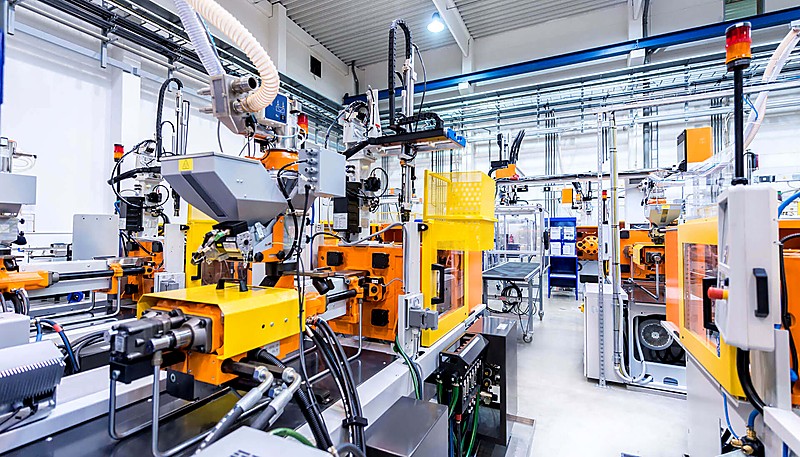
Designing an 사출 금형 involves several key steps like material selection, cavity layout, and part geometry considerations for optimal results and high production efficiency.
Understanding mold design principles is essential for efficient production and high-quality output. Whether you are designing a new mold or optimizing an existing tool, these factors directly influence mold performance, cycle time, and overall cost savings for manufacturers.
- Mold material choice (steel vs aluminum) directly impacts tool life and part quality
- Proper cooling channel layout can reduce cycle time by up to 70%
- Uniform wall thickness is the single most critical design factor
- Vent groove depth of 0.01–0.03 mm prevents flash while allowing gas escape
- Regular mold maintenance extends tool life and maintains dimensional accuracy
사출 금형의 기본 원리는 무엇인가요?
사출 금형은 용융된 재료를 금형 캐비티에 주입하는 공정을 사용하여 고정밀 부품을 생산하는 데 필수적입니다. 이 기술은 많은 산업에서 빠르고 일관된 생산을 보장하는 기반이 됩니다.
If you are comparing vendors or planning procurement, our injection molding supplier sourcing guide covers RFQ prep, qualification, and commercial risk checks.
사출 성형 공정 injects molten material into a mold cavity under high pressure, where it solidifies to form the desired product. Mold design ensures the product can be easily removed and closely matches the expected dimensions.

The materials, structure, and layout of injection molds directly relate to the quality, efficiency, and cost of the final product.
사출 금형 설계의 기본 원칙에는 다음과 같은 몇 가지 주요 단계가 포함됩니다.
Preparation of molten plastic is the first stage. The plastic raw material is melted by the shearing action of the screw and the heater.
Injection: The molten plastic is forced into the mold cavity through the nozzle with help of pressure exerted by the screw.
With over 20 years of injection mold design experience, ZetarMold operates 47 injection molding machines (90T–1850T) at our Shanghai factory, handling mold designs for parts of virtually any size and complexity.
Holding Pressure and Cooling: The injection molding machine keeps this pressure for some time to ensure that the cavity is filled and then starts cooling process as the plastic starts to set.
After the plastic solidifies, the mold opens and the ejection system — typically pins, plates, or sleeves — pushes the finished part out of the cavity. Proper ejection design ensures the part releases cleanly without deformation or damage to critical surfaces.
“Proper mold design reduces defects and improves production efficiency.”True
Well-designed injection molds achieve consistent part quality, lower scrap rates, and shorter cycle times across production runs.
“Injection mold design is only about the product shape.”False
Mold design also includes material selection, cooling system layout, ejection mechanisms, and process optimization for efficient production.
금형 재료란 무엇인가요?
Mold materials are essential in manufacturing processes like injection molding, ensuring durability, precision, and quality. The choice of material affects production efficiency and the final product’s characteristics.
금형 재료의 선택은 금형의 수명과 완제품의 품질에 큰 영향을 미칩니다. 일반적인 금형 재료는 강철과 알루미늄입니다.
Steel
Steel molds offer superior hardness, wear resistance, and heat treatment properties with significantly longer working life than aluminum — ideal for high-volume production where dimensional consistency is critical.
The main drawbacks of steel molds are longer machining times and higher material costs compared to aluminum. Steel is also significantly heavier, which increases handling difficulty and wear on mold-change equipment. However, the longer tool life usually offsets these disadvantages in high-volume applications.
일반 강철:
P20 스틸1 is a versatile pre-hardened mold steel (28–36 HRC) widely used for mold bases and large cavities. It offers excellent machinability and polishability at a cost-effective price point for medium-volume production molds.
H13 is a hot-work tool steel for molds operating at elevated temperatures. It maintains hardness and thermal stability after prolonged heat exposure, with typical hardness of 44–52 HRC after treatment.
S136 is a stainless tool steel with excellent corrosion resistance and polishability. It is the preferred choice for optical lenses, transparent parts, and medical molds where surface finish quality is paramount.
알루미늄
Aluminum molds offer significant weight savings and roughly 4–5x better thermal conductivity than steel, enabling faster cooling and shorter cycle times. Easy machinability reduces tooling lead time and cost, making aluminum ideal for prototyping and low-volume production.
The main drawback is lower hardness and wear resistance, making aluminum molds susceptible to surface damage with abrasive resins. Best suited for production runs under 10,000–50,000 parts where tooling speed matters more than longevity.
일반적인 알루미늄:
7075 is one of the strongest aluminum grades (tensile strength ~570 MPa). Despite this, its hardness remains far below tool steel, making it best suited for prototype molds and short production runs.
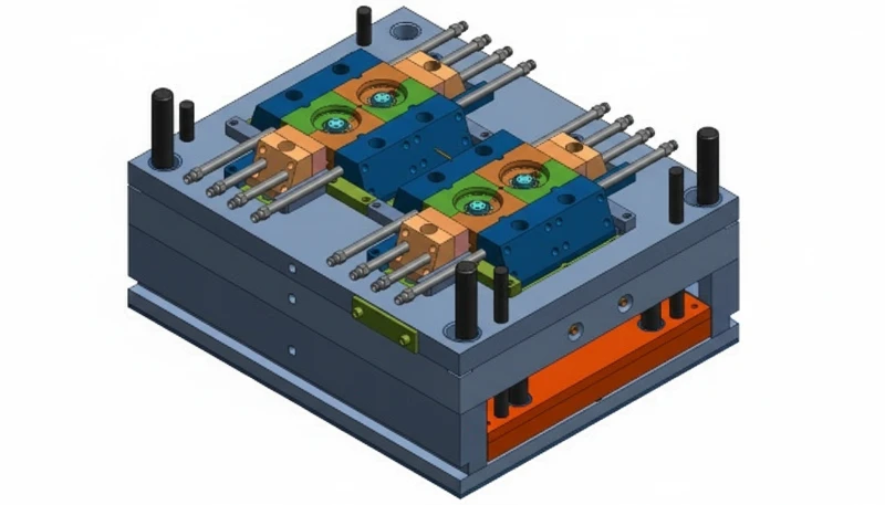
금형 구조 설계에는 주로 무엇이 포함되나요?
금형 구조 설계는 고품질 사출 금형을 제작하고 성형 공정의 효율성과 일관성을 보장하는 데 핵심적인 역할을 합니다. 여기에는 금형 흐름, 냉각 및 재료 호환성과 같은 중요한 측면이 포함됩니다.
Mold structure design refers to the cavity, core, frame, gate, guide, and withdrawal system. All must be carefully engineered for proper efficiency, sturdiness, and easy maintenance.
캐비티 및 코어
캐비티는 제품의 외형 치수를 생성하고 코어는 내부 치수를 결합하여 최종적으로 원하는 제품 모양과 크기를 제공합니다.
Material Selection: Often employ high-hardness, wear-resistant steel, such as P20 or H13 steel.
Design Points: The finished surfaces of cavity & core should be smooth so that high dimensional accuracy should be maintained for the surface finish of the product.
몰드 베이스
몰드 베이스는 도구의 골격이 되는 프레임워크이며 모든 구성 요소를 고정하고 연결하는 역할을 합니다. 일반적으로 금형을 조립하고 필요할 때 교체할 수 있는 표준 형태가 있습니다.
Material Selection: Usually, 45 steel or Q235 steel is adopted for the mold base to guarantee the stability of the mold base.
At ZetarMold, our in-house mold manufacturing facility produces over 100 mold sets per month using UG, SOLIDWORKS, MOLDFLOW, and CAD to simulate mold flow and validate cooling designs before machining begins.
“Mold structure design directly impacts part quality and production efficiency.”True
Proper cavity layout, cooling channel placement, and ejection system design determine dimensional accuracy, cycle time, and defect rates.
“All mold structures are the same regardless of the application.”False
Mold structures vary significantly depending on part geometry, material properties, production volume, and industry-specific requirements.
Design Points: The mold base should possess enough robustness and sturdiness to be able to cope with injection pressure, injection temperature and the general to and fro pressure during injection.
게이팅 시스템

게이팅 시스템은 1차 러너, 서브 러너, 용융된 플라스틱을 캐비티로 유도하는 게이트로 구성됩니다. 효과적인 게이팅 시스템은 성형 품질을 높이고 사용되는 재료의 양을 줄이는 데 도움이 됩니다.
Design Points: The main runner should be as short and as straight as can be in order to minimize the pressure loss as well as cuts as much as is possible.
Design Points: Sub-runners should be properly arranged so that it would apply equal mass to the cavity.
Design Points: The nature of the gate should not in any way influence the look of the product or compromise on its strength The size of the gate used should be good.
안내 메커니즘
가이드 메커니즘에는 가이드 핀과 부싱이 포함되어 있어 움직이는 금형과 고정 금형 간의 정렬을 도와줍니다.
Material Selection: Typically uses high-hardness steel, such as GCr15.
Design Points: The guiding mechanism should be very accurate in term of the alignment to prevent misalignment over a long period of time besides being very resistant to wear.
배출 메커니즘
이젝션 부품은 성형된 제품을 금형에서 꺼내기 위해 적용되며 일반적으로 이젝션 핀, 플레이트 및 슬리브가 사용됩니다.
Design Points: Another requirement of this force is that it should be constant or smooth since a sudden force may affect the product in a negative way. The movement of the ejection mechanism should also be smooth to avoid sticking.
플로우 채널 디자인이란 무엇인가요?
Flow channel design is the engineering of the sprue, runners, and gates that guide molten plastic from the machine nozzle into the mold cavity.
Runner design significantly influences product quality and production efficiency. The size and shape of the runner must match the material and part geometry.
메인 주자
메인 러너는 사출기 노즐과 서브 러너를 연결하며 압력 손실과 재료 낭비를 줄이기 위해 가능한 한 짧고 직선으로 만들어야 합니다.
Design Points: The main runner diameter should be right to promote adequate flow all the same reduce wasteful use of the materials.
하위 주자
서브 러너는 플라스틱 용융물을 금형의 각 캐비티에 분배하며, 이때 균형을 가장 중요하게 고려해야 합니다.
Design Points: Sub-runner cross-sectional shapes should be best circular or semicircular to lower the resistance offered by flows. The length should ideally be as equal as possible, so that the cavity filling time is almost equal for all the lengths.
Gates
게이트는 캐비티에 유입된 용융 플라스틱이 제품 품질에 영향을 미치는 수단입니다.
Design Points: The gates should be placed in areas that do not affect appearance or strength. Their sizes must provide adequate fill rates while being easy to remove. Different gate types serve different product requirements.
또한 러너 디자인도 고려해야 합니다:
Runner Balance: For multiple cavities make sure that the runners lengths and their cross sectional area as they are the primary determinet of the time taken to fill the molds.
Runner Cooling: Sufficient provision for 냉각 채널2 for the runner section so that high temperature does not influence the melt flow.
Runner Precision: Machining precision is high and the surface smooth to lower the restriction to melt flow and pressure drop.
냉각 시스템 설계란 무엇인가요?
냉각 시스템 설계는 제조 공정을 최적화하고 생산 주기에서 일관된 제품 품질과 효율성을 보장하는 데 매우 중요합니다.
“Flow channel design significantly affects molding efficiency and part quality.”True
Optimized runner and gate geometry reduces material waste, shortens cycle time, and improves fill consistency across cavities.
“Flow channel design is identical for all mold types and materials.”False
Flow channel geometry must be customized based on material viscosity, part thickness, gate type, and cavity layout for optimal fill patterns.
냉각 시스템은 사출 성형 사이클 시간과 금형 품질을 감소시키기 때문에 사출 금형 설계에서 매우 중요한 역할을 합니다. 냉각 시스템에는 주로 냉각 채널과 냉각 시간 단계가 포함됩니다.
냉각 채널
냉각 채널은 냉각수를 다양한 금형 부품으로 안내하여 과도한 열을 제거합니다.
Cooling channels should be positioned as close to the cavity surface as possible to maximize heat dissipation. A channel-to-cavity distance of 1.5–2.5 times the channel diameter balances cooling performance with structural integrity of the mold steel.
Coolant flow should be distributed evenly across all channels to prevent localized hot spots. Uneven cooling leads to differential shrinkage, internal stresses, and warpage in the finished part. Baffles or spiral inserts can help redirect flow to underserved areas of the mold.
Channel diameter must be large enough to maintain adequate coolant flow velocity — typically 1.5–3 m/s — without creating excessive pressure drop. Too-small diameters risk blockages from scale or debris, while overly large channels reduce flow turbulence and heat transfer efficiency.
냉각 시간
Cooling time also depends with the wall thicknesses of the product, the type of material used, and the temperatures of the mold.
Sufficient cooling time prevents warpage and shrinkage while ensuring dimensional stability. The optimal duration balances part integrity against throughput — typically 60–80% of total cycle time in most injection molding operations.
냉각 시스템에 대한 다른 고려 사항은 다음과 같습니다:
Coolant flow speed requires careful control. Low speed can reduce cooling efficiency, while high speed might lead to blockage and wearing of the mold.
Coolant Temperature: Optimal temperature, as high temperature decrease the cooling rate while low temperature will cause condensation on the mould surface and may affect the quality of the product.
Coolant Quality: Keep coolant clean to avoid blockages and mold damage.
배기 시스템 설계란 무엇인가요?
Exhaust system design is the engineering of vent grooves and holes that allow trapped air and gases to escape the mold cavity during injection.
환기 시스템은 금형 캐비티에서 가스를 배출하여 기포 및 화상과 같은 결함을 방지하여 제품 품질과 금형 수명에 직접적인 영향을 미칩니다.
통풍 홈
Relief groove3 is a channel for the escape of gas and it is mostly in the parting line.
Design Points: Put location grooves where/when gas can freely build up.
Design Points: Width and depth should optimise cross-sectional area for the required venting so that there will not be any issues on the side of plastic ejection.
Design Points: Even distribution to prevent localized venting issues.
통풍구
통풍구는 일반적으로 제품의 얇은 부분에 위치한 통풍 시스템의 구성 요소 중 하나입니다.
Design Points: Appropriate diameter in order not to hinder the release of gas build up while at the same time guaranteeing proper exhaust.
Design Points: Positioning should not in any way influence the look of the product and neither its strength.
Design Points: Quantity and location should be reasonable with the structure of mould and the shape of product.
환기 시스템 설계도 고려해야 합니다:
System Maintenance: They should be cleaned now and then to ensure unrestricted and unhindered flow but be checked at times to avoid tools to avoid blockages that may cause quality issues.
System Cooling: In the case of using high-temperature molds, make use of cooling means to avoid condensation of the gases during the time of venting.
Processing Precision: High precision with smooth surfaces to reduce gas flow resistance and pressure loss.
ZetarMold processes over 400 plastic materials. Our 8 senior engineers oversee mold processing quality under ISO 9001, ISO 13485, ISO 14001, and ISO 45001 certified management systems.
금형 가공이란 무엇인가요?
Mold processing is the series of CNC machining, EDM, grinding, and surface treatment steps that transform raw steel into a precision injection mold.
“Proper mold processing ensures dimensional accuracy and surface quality.”True
CNC machining, EDM, and surface treatment of mold components create precise tolerances and smooth surfaces for consistent part production.
“Mold processing is only necessary for high-volume production molds.”False
All molds require proper machining, heat treatment, and surface finishing regardless of production volume to achieve required tolerances.
금형 가공은 설계 도면을 황삭 가공, 미세 가공, 표면 처리 등을 통해 실제 금형으로 변환하는 과정입니다. 분석을 통해 가공 정확도와 품질이 금형의 기능과 내구성에 직접적인 영향을 미친다는 것을 알 수 있습니다.
거친 가공
원재료의 금형에서 거친 가공이 이루어지며 일반적으로 사용되는 장비는 CNC 밀링 및 선반입니다.
Key Points: Leave sufficient allowance for finishing.
Key Points: The optimum speed and feed rates that help in avoiding deformation of the material and gradual wearing of the tools and machinery.
Key Points: Rough machining to decrease the burr and bringing the smoother surface.
마무리
마감은 금형의 크기와 사양에 맞게 금형을 완성하고 연삭 공정, EDM 및 연마 작업을 통해 이루어집니다.
Key Points: Accuracy ensure that the shape and size is correct for the mold.
Key Points: Avoid over-polishing to prevent dimensional deviations.
Key Points: Finishing the surface with the best and most appropriate equipment in order to obtain a smooth and proper finish.
표면 처리
금형 표면 처리는 담금질, 질화, 표면 코팅 사용 등의 공정을 통해 금형 경도와 내마모성을 향상시킵니다.
Key Points: Select appropriate treatment methods based on mold material and application.
Key Points: To reduce mold deformation and cracks the amount of time for treatment and temperature should be controlled.
Key Points: Clean thoroughly before treatment for better adhesion and performance.
곰팡이는 어떻게 관리하나요?
사출 성형에서 일관된 품질과 수명을 보장하기 위해서는 적절한 금형 유지 관리가 중요합니다. 정기적인 관리를 통해 가동 중단과 고비용 수리를 방지할 수 있습니다.
Mold maintenance, both daily and periodic, extends service life and reduces production costs through consistent upkeep.
정기 유지 관리
Key Points: Ensure the mold surface is as clean to avert temperatures and dust from penetrating the mold.
Key Points: Lubricate the guide pillar and guide bushing regularly to ensure the flexibility of the guide mechanism.
Key Points: It may be necessary to often inspect the other components of the mold, and repair or replace them in time.
Key Points: It is necessary to confirm whether the cooling channel and exhaust system are normally opened and whether they are blocked, if they are blocked, they should be cleared up in time.
정기 유지보수
유지 관리란 금형을 일정 기간 사용한 후 일반적인 점검 및 수리를 의미합니다.
Key Points: Inspect the mold cavity and core and look for the part of the cavity which has severely worn and repair or replace them.
Key Points: Check whether the guiding mechanism, demoulding mechanism and other parts of the mold are normal, and make necessary adjustments or replacements.
Key Points: Check whether the cooling system of the mold and the exhaust system of the mold are normal and perform the need for cleaning and clearing.
Key Points: Thoroughly clean and lubricate the mold to ensure that the mold is in good working condition.
금형 설계의 일반적인 문제와 그 해결책은 무엇인가요?
Common mold design problems include poor cooling, uneven material flow, and improper gate placement that affect part quality.
“Regular cleaning extends mold lifespan and maintains part quality.”True
Scheduled maintenance including cleaning, lubrication, and inspection prevents wear, corrosion, and dimensional drift over production cycles.
“Mold maintenance is unnecessary if the mold is properly designed.”False
All molds require regular cleaning and inspection regardless of design quality to maintain dimensional accuracy and prevent progressive wear.
Several common issues can affect part quality and production rate if not properly addressed during mold design.
싱크 마크
Problem Description: The surface of the product is dented, which affects the appearance.
Solution: It is advised to the position as well as the size of the gate to be such that it can accommodate melt and fill up the cavity uniformly.
Solution: Maximize the cooling circuit design and layout in order to allow equal distribution of the cooling to the products.
Solution: Adjust the holding time and pressure to reduce melt shrinkage.
플래시
Problem Description: Scrap forms on the peripheral region of the product giving it a poor appearance and may not be of accurate dimension.
Solution: About the parting surface design of the mold, try to make the mold closed to the minimum.
Solution: Enhance the clamping force of the mold to prevent the mold from separating during the injection molding manufacturing process.
Solution: To check the mold, first it is required to check the guiding mechanism of the mold and the clamping mechanism of the mold.
Bubble
Problem Description: There are visible pores on the body of the product or in the product itself in the form of bubbles which influences the looks and the durability.
Solution: Minimize the design of the exhaust system so as to allow the gas in the mold cavity to be released effectively.
Solution: Adjust the parameters used in injection like the speed of injection, injection force and temperature of injection molding materials in a bid to minimize generation of gases.
Solution: Check the drying of raw materials to ensure that the moisture content of raw materials is at an appropriate level.
변형 및 뒤틀림
Problem Description: The injection molded part becomes partly shrunken or distorted after cooling and the dimensional stability and surface finish of the product are compromised.
Solution: Improve on the cooling system so as to give as equal temperatures to all the injection molded parts.
Solution: Adjust the holding time and holding pressureset in the injection parameters to reduce internal stress.
Solution: Strengthen the changes in mold structure design, such as adding reinforcing ribs to make the product have uniform wall thickness and consistent wall thickness.

차원 불안정성
Problem Description: The geometry is out of the required sizes and standards to affect the assembly and usage of the product.
Solution: Examine the correctness of machining on the mold and assembly realization of products to verify whether or not the sizes of the mold conform with the injection molding design specifications.
Solution: Control the process parameters as injection pressure, holding pressure time and cooling time should be controlled in order to have stable size of the product.
Solution: Confirm the manufacture stability of the injection molding machines in order to have ability to determine the variation of the injection molding.
자주 묻는 질문
What is the most important factor in injection mold design?
The most critical factor in injection mold design is achieving uniform wall thickness throughout the part. Uneven walls cause differential cooling, which directly leads to sink marks, warpage, and dimensional inconsistency in the finished product. In our experience at ZetarMold working with over 400 materials, parts with wall thickness variations exceeding 15 percent almost always require costly mold rework to achieve acceptable quality. Beyond wall thickness, proper gate placement and an efficient cooling system layout are equally important for determining cycle time and long-term mold durability.
How long does it take to design an injection mold?
A typical injection mold design takes 2 to 4 weeks depending on part complexity. Simple single-cavity molds for straightforward geometries may take as little as 5 to 7 days from concept to completed drawings. Complex multi-cavity molds with side actions, lifters, or unscrewing mechanisms can require 4 to 6 weeks of engineering time. The design phase includes 3D CAD modeling, mold flow simulation to validate fill patterns, and multiple design review iterations. At ZetarMold, our 8 senior engineers follow a structured review process that catches issues early.
What software is used for injection mold design?
The industry standard software for injection mold design includes SOLIDWORKS and UG also known as NX for 3D CAD modeling, and Autodesk Moldflow for flow simulation and thermal analysis. These tools allow engineers to visualize cavity layout, simulate plastic fill patterns, and optimize cooling channel placement before any steel is cut. At ZetarMold, our design team uses SOLIDWORKS, MOLDFLOW, and CAD in combination to validate gate placement, predict weld line positions, and analyze cooling efficiency, reducing first-article defects by up to 60 percent compared to traditional trial-and-error methods.
What is the typical cost of an injection mold?
Injection mold costs range widely depending on complexity and production requirements. Simple single-cavity aluminum prototype molds start around 1,000 to 3,000 dollars, while production-grade steel molds with multiple cavities and hot runner systems typically cost between 10,000 and 50,000 dollars. Highly complex molds with side actions, unscrewing cores, or specialized surface finishes can exceed 100,000 dollars. Key cost drivers include the number of cavities, mold material choice, expected production volume, required surface finish quality, and tolerance specifications for the application.
How do you prevent flash in injection mold design?
Flash prevention starts with precision parting surface design and proper clamping force calculation. The mold parting line must be machined to flatness tolerances within 0.01 millimeters to ensure complete closure under injection pressure. Vent grooves should be sized correctly at 0.01 to 0.03 millimeters depth to allow trapped gas to escape without permitting molten material to seep through. The injection molding machine must have sufficient tonnage. At ZetarMold, our 47 presses range from 90T to 1850T, allowing precise matching of machine capacity to each mold.
What is the difference between a cold runner and a hot runner mold?
A cold runner mold channels molten plastic through unheated passages, resulting in solidified runner waste that must be separated, reground, and recycled or discarded. A hot runner mold uses electrically heated manifold systems to keep plastic in a molten state within the distribution channels, eliminating runner waste entirely and reducing cycle time. Hot runner molds cost 20 to 40 percent more upfront due to the heated manifold and temperature controllers, but they save 15 to 30 percent on material costs for high-volume production runs and improve consistency.
What tolerance can injection molding achieve?
Standard injection molding achieves tolerances of plus or minus 0.1 millimeters for dimensions under 25 millimeters. Precision molding with optimized process control, tight temperature regulation, and high-quality tooling can achieve plus or minus 0.05 millimeters or tighter for critical features. Tolerance capability depends heavily on material shrinkage characteristics, with semi-crystalline materials exhibiting higher variability than amorphous ones. For tight-tolerance applications, ZetarMold engineers use Moldflow simulation during the design phase to predict and compensate for shrinkage before the mold is built.
Why Does Injection Mold Design Matter for Manufacturing Success?
Injection mold design is the most important factor for part quality, production efficiency, and cost control in plastic manufacturing.
This article provides practical references for injection mold designers. For custom mold design support, contact ZetarMold for expert assistance.
Learn about Injection Molding: A Comprehensive Guide: Injection molding is a manufacturing process where molten plastic is injected into a mold to create parts with high accuracy and repeatability. ↩
Learn about What is core and cavity in injection molding? The cavity and core in a typical plastic injection molding machine of an injection mold are the molding parts of the mold . ↩
Learn about Types Of Gates for Injection Molding: A Complete Design Guide : An injection molding gate is a designed opening, usually small, that controls molten plastics flow into the mold cavity. ↩
Learn about H13 Tool Steel : H13 is a hot work tool steel that has good resistance to thermal fatigue, erosion and wear, and is widely used for making molds and dies. ↩
Learn about Four Important Principles Should Be Considered In The Design Of Wall Thickness : Plastic Product wall thickness is a critical structural feature frequently discussed and considered in the design of plastic product structures. ↩
Learn about How to Determine Holding Pressure and Holding Time In Injection Molding? injection pressure includes both pressure and speed . ↩
Get competitive pricing, DFM feedback, and production timeline from ZetarMold’s engineering team.
Request a Free Quote →


