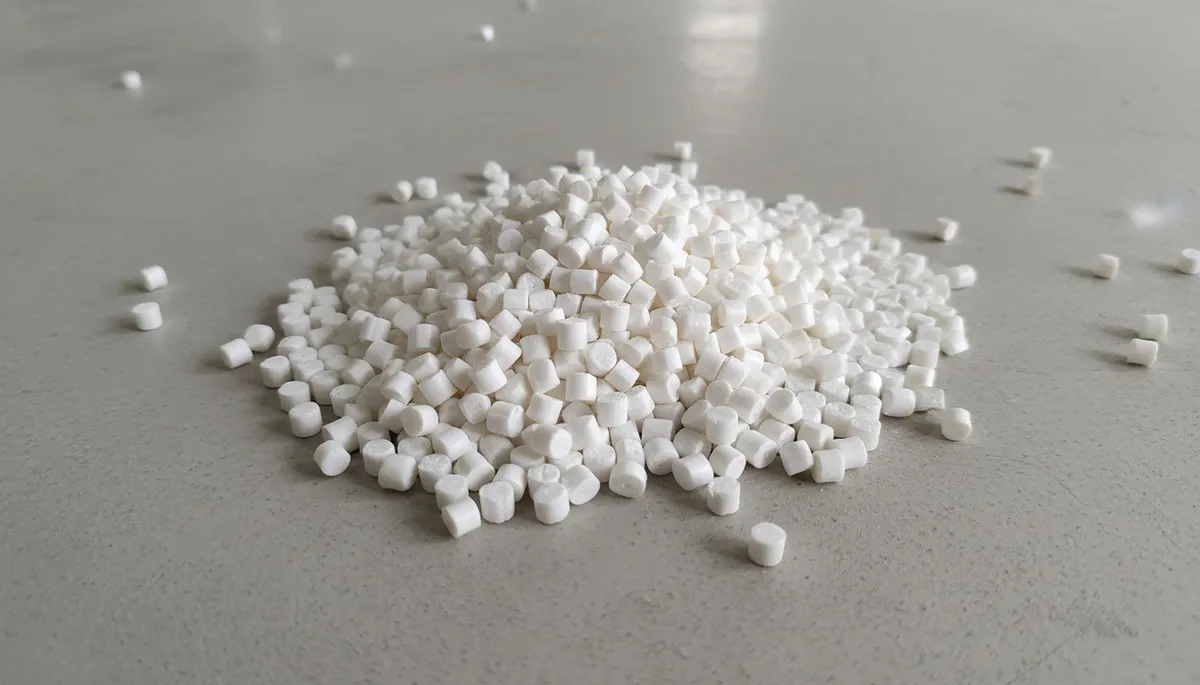
La progettazione di uno stampo a iniezione comprende diverse fasi chiave, come la scelta del materiale, la disposizione delle cavità e la valutazione della geometria del pezzo, per ottenere risultati ottimali e un’elevata efficienza produttiva.
Comprendere i principi di progettazione dello stampo è essenziale per una produzione efficiente e un prodotto di alta qualità. Che tu stia progettando un nuovo stampo o ottimizzando uno strumento esistente, questi fattori influenzano direttamente le prestazioni dello stampo, il tempo di ciclo e il risparmio sui costi complessivo per i produttori.
- La scelta del materiale dello stampo (acciaio vs alluminio) influisce direttamente sulla vita dell'utensile e sulla qualità del pezzo
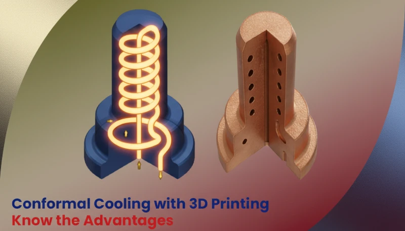
- Una corretta disposizione dei canali di raffreddamento può ridurre il tempo di ciclo fino al 70%
- Lo spessore uniforme delle pareti è il singolo fattore di progettazione più critico
- Una profondità della scanalatura di sfiato di 0,01-0,03 mm previene le bave consentendo la fuoriuscita dei gas
- La manutenzione regolare dello stampo prolunga la vita dell'utensile e mantiene l'accuratezza dimensionale
Quali sono i principi di base degli stampi a iniezione?
Gli stampi a iniezione sono essenziali per la produzione di pezzi di alta precisione, grazie a un processo in cui il materiale fuso viene iniettato in una cavità dello stampo. Questa tecnologia è alla base di molti settori industriali e garantisce una produzione rapida e costante.
Se state confrontando fornitori o pianificando gli acquisti, la nostra guida alla selezione dei fornitori di stampaggio a iniezione tratta la preparazione delle RFQ, la qualificazione e i controlli sui rischi commerciali.
Il processo di stampaggio a iniezione immette materiale fuso ad alta pressione nella cavità dello stampo, dove solidifica formando il prodotto desiderato. La progettazione dello stampo garantisce che il prodotto possa essere estratto facilmente e rispetti fedelmente le dimensioni previste.
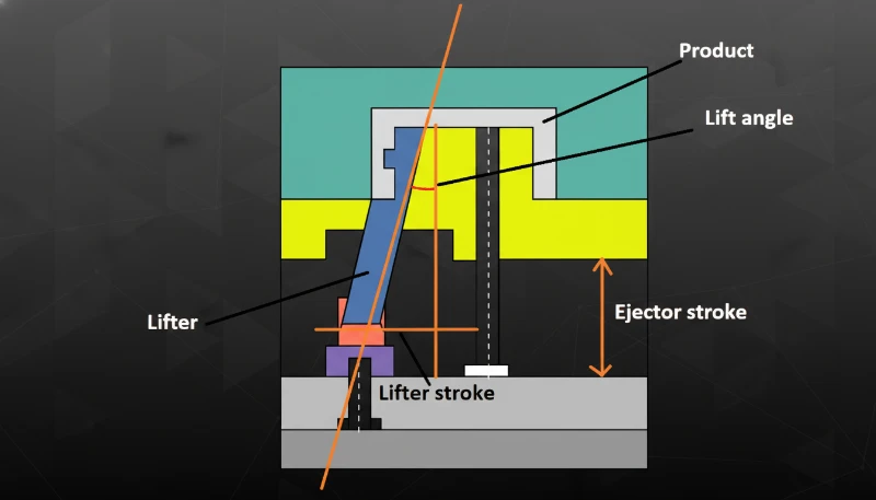
I materiali, la struttura e il layout degli stampi a iniezione sono direttamente correlati alla qualità, all’efficienza e al costo del prodotto finale.
I principi di base della progettazione di uno stampo a iniezione comprendono diverse fasi fondamentali
La preparazione della plastica fusa è la prima fase. La materia prima plastica viene fusa dall’azione di taglio della vite e del riscaldatore.
Iniezione: La plastica fusa viene forzata nella cavità dello stampo attraverso l’ugello con l’aiuto della pressione esercitata dalla vite.
Con oltre 20 anni di esperienza nella progettazione di stampi a iniezione, ZetarMold opera 47 macchine per stampaggio a iniezione (90T–1850T) nella nostra fabbrica di Shanghai, gestendo progetti di stampi per parti di praticamente qualsiasi dimensione e complessità.
Pressione di mantenimento e raffreddamento: La macchina per stampaggio a iniezione mantiene questa pressione per un certo periodo per garantire che la cavità sia riempita e poi avvia il processo di raffreddamento quando la plastica inizia a solidificarsi.
Dopo che la plastica si solidifica, lo stampo si apre e il sistema di espulsione — tipicamente spinotti, piastre o manicotti — spinge il pezzo finito fuori dalla cavità. Un corretto design dell’espulsione garantisce che il pezzo si rilasci pulito senza deformazioni o danni alle superfici critiche.
"Una corretta progettazione dello stampo riduce i difetti e migliora l'efficienza produttiva."True
Stampi per iniezione ben progettati garantiscono una qualità costante dei pezzi, tassi di scarto inferiori e tempi di ciclo più brevi durante le produzioni.
"La progettazione dello stampo a iniezione riguarda soltanto la forma del prodotto."False
Il design dello stampo include anche la selezione del materiale, la disposizione del sistema di raffreddamento, i meccanismi di espulsione e l'ottimizzazione del processo per una produzione efficiente.
Quali sono i materiali dello stampo?
I materiali per stampi sono essenziali nei processi di produzione come lo stampaggio a iniezione, garantendo durabilità, precisione e qualità. La scelta del materiale influisce sull’efficienza produttiva e sulle caratteristiche del prodotto finale.
La scelta del materiale dello stampo ha un grande impatto sulla durata dello stampo e sulla qualità del prodotto finito. I materiali più comuni per gli stampi sono l’acciaio e l’alluminio.
Acciaio
Gli stampi in acciaio offrono durezza superiore, resistenza all’usura e proprietà di trattamento termico con una vita lavorativa significativamente più lunga rispetto all’alluminio, ideali per la produzione ad alto volume dove la coerenza dimensionale è critica.
I principali svantaggi degli stampi in acciaio sono tempi di lavorazione più lunghi e costi del materiale più elevati rispetto all’alluminio. L’acciaio è anche significativamente più pesante, il che aumenta la difficoltà di manipolazione e l’usura delle apparecchiature per il cambio stampo. Tuttavia, la maggiore durata dell’utensile di solito compensa questi svantaggi nelle applicazioni ad alto volume.
Acciai comuni:
L’acciaio P201 è un versatile acciaio pretemprato per stampi (28–36 HRC), ampiamente utilizzato per portastampi e cavità di grandi dimensioni. Offre eccellente lavorabilità e lucidabilità a un costo conveniente per stampi destinati a volumi di produzione medi.
H13 è un acciaio per utensili da lavoro a caldo per stampi che operano a temperature elevate. Mantiene durezza e stabilità termica dopo prolungata esposizione al calore, con una durezza tipica di 44–52 HRC dopo il trattamento.
S136 è un acciaio per utensili inossidabile con eccellente resistenza alla corrosione e lucidabilità. È la scelta preferita per lenti ottiche, parti trasparenti e stampi medicali dove la qualità della finitura superficiale è fondamentale.
Alluminio
Gli stampi in alluminio offrono un notevole risparmio di peso e una conduttività termica circa 4-5 volte migliore rispetto all’acciaio, consentendo un raffreddamento più rapido e tempi di ciclo più brevi. La facile lavorabilità riduce i tempi di consegna e i costi degli utensili, rendendo l’alluminio ideale per prototipazione e produzione a basso volume.
Il principale svantaggio è la minore durezza e resistenza all’usura, rendendo gli stampi in alluminio suscettibili a danni superficiali con resine abrasive. Più adatti per produzioni sotto le 10.000-50.000 parti dove la velocità di realizzazione dello stampo è più importante della longevità.
Alluminio comune:
7075 è uno dei gradi di alluminio più resistenti (resistenza alla trazione ~570 MPa). Nonostante ciò, la sua durezza rimane molto inferiore a quella dell’acciaio per utensili, rendendolo più adatto per stampi prototipo e brevi serie di produzione.
Cosa comprende principalmente la progettazione della struttura dello stampo?
La progettazione della struttura dello stampo è fondamentale per creare stampi a iniezione di alta qualità, garantendo efficienza e coerenza durante il processo di stampaggio. Si tratta di aspetti critici come il flusso dello stampo, il raffreddamento e la compatibilità dei materiali.
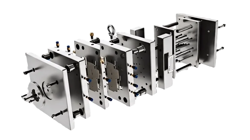
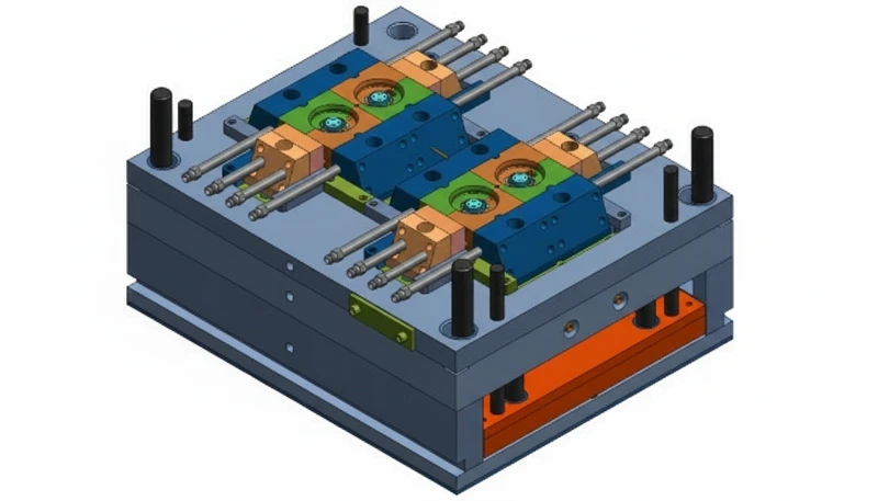
La progettazione della struttura dello stampo si riferisce alla cavità, al nucleo, al telaio, al gate, alla guida e al sistema di estrazione. Tutti devono essere progettati con cura per garantire un’efficienza adeguata, solidità e facile manutenzione.
Cavità e nucleo
La cavità crea le dimensioni esterne del prodotto, mentre l’anima fornisce le dimensioni interne legate insieme per fornire la forma e le dimensioni finali e desiderate del prodotto.
Selezione del materiale: Spesso si impiega acciaio ad alta durezza e resistenza all’usura, come l’acciaio P20 o H13.
Punti di progettazione: le superfici finite di cavità e maschio devono essere lisce, affinché la finitura superficiale del prodotto mantenga un’elevata precisione dimensionale.
Base dello stampo
La base dello stampo è anche l’ossatura dell’utensile e ha il compito di fissare e collegare tutti i componenti. Di solito ha una forma standard per consentire l’assemblaggio degli stampi e la loro sostituzione quando necessario.
Selezione del materiale: Solitamente, per la base dello stampo si adotta acciaio 45 o acciaio Q235 per garantire la stabilità della base dello stampo.
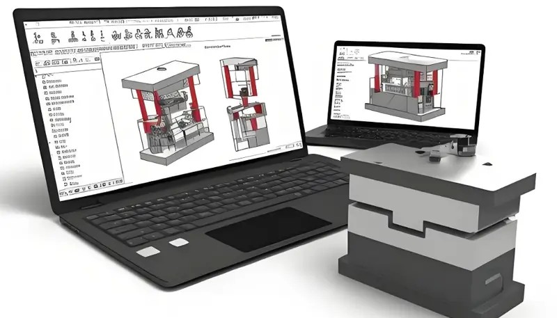
Presso ZetarMold, il nostro stabilimento interno di produzione di stampi produce oltre 100 set di stampi al mese utilizzando UG, SOLIDWORKS, MOLDFLOW e CAD per simulare il flusso dello stampo e convalidare i progetti di raffreddamento prima che inizi la lavorazione.
"La progettazione della struttura dello stampo incide direttamente sulla qualità del pezzo e sull'efficienza produttiva."True
La corretta disposizione della cavità, il posizionamento dei canali di raffreddamento e il design del sistema di espulsione determinano la precisione dimensionale, il tempo di ciclo e i tassi di difettosità.
"Tutte le strutture degli stampi sono uguali indipendentemente dall'applicazione."False
Le strutture degli stampi variano notevolmente in base alla geometria del pezzo, alle proprietà del materiale, al volume di produzione e ai requisiti specifici del settore.
Punti di progettazione: La base dello stampo deve possedere sufficiente robustezza e solidità per poter far fronte alla pressione di iniezione, alla temperatura di iniezione e alla pressione generale avanti e indietro durante l’iniezione.
Sistema di regolazione
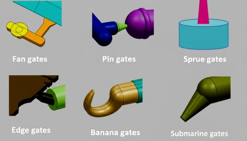
Il sistema di chiusura comprende il canale primario, i canali secondari e le porte attraverso le quali la plastica fusa viene condotta nella cavità. Un sistema di chiusura efficace è utile per aumentare la qualità dello stampaggio e ridurre la quantità di materiale utilizzato.
Punti di design: Il canale principale dovrebbe essere il più corto e dritto possibile per minimizzare la perdita di pressione e ridurre al massimo gli scarti.
Punti di design: I canali secondari devono essere disposti correttamente in modo da applicare una massa uguale alla cavità.
Punti di progettazione: La natura del gate non deve in alcun modo influenzare l’aspetto del prodotto o comprometterne la resistenza. La dimensione del gate utilizzato dovrebbe essere adeguata.
Meccanismo di guida
Il meccanismo di guida comprende perni di guida e boccole, che aiutano l’allineamento tra lo stampo mobile e quello fisso.
Selezione del materiale: Tipicamente si utilizza acciaio ad alta durezza, come il GCr15.
Punti di progettazione: Il meccanismo di guida dovrebbe essere molto preciso in termini di allineamento per prevenire disallineamenti nel lungo periodo oltre ad essere molto resistente all’usura.
Meccanismo di espulsione
La parte di espulsione viene applicata per estrarre il prodotto stampato dallo stampo e normalmente vengono utilizzati perni di espulsione, piastre e manicotti.
Punti di progettazione: Un altro requisito di questa forza è che dovrebbe essere costante o fluida poiché una forza improvvisa potrebbe influire negativamente sul prodotto. Anche il movimento del meccanismo di estrazione dovrebbe essere fluido per evitare l’adesione.
Che cos’è la progettazione dei canali di flusso?
La progettazione del canale di flusso è l’ingegnerizzazione del materozzo, dei canali di distribuzione e degli attacchi che guidano la plastica fusa dall’ugello della macchina alla cavità dello stampo.
La progettazione dei canali di distribuzione influenza significativamente la qualità del prodotto e l’efficienza produttiva. La dimensione e la forma del canale di distribuzione devono corrispondere al materiale e alla geometria del pezzo.
Corridore principale
Il canale principale collega l’ugello della macchina di iniezione ai canali secondari e deve essere il più corto e rettilineo possibile per ridurre le perdite di pressione e lo spreco di materiale.
Punti di progettazione: Il diametro del canale di distribuzione principale dovrebbe essere corretto per promuovere un flusso adeguato e allo stesso tempo ridurre lo spreco di materiali.
Sub-runner
I canali secondari distribuiscono la colata di plastica in ogni cavità dello stampo e l’equilibrio deve essere un aspetto importante.
Punti di progettazione: Le forme della sezione trasversale dei sotto-canali di distribuzione dovrebbero essere preferibilmente circolari o semicircolari per ridurre la resistenza offerta dai flussi. La lunghezza dovrebbe idealmente essere la più uguale possibile, in modo che il tempo di riempimento della cavità sia quasi uguale per tutte le lunghezze.
Cancelli
Le porte sono il mezzo attraverso il quale la plastica fusa introdotta nella cavità ha un impatto sulla qualità del prodotto.
Punti di progettazione: I gate devono essere posizionati in aree che non influenzano l’aspetto o la resistenza. Le loro dimensioni devono fornire adeguati tassi di riempimento pur essendo facili da rimuovere. Diversi tipi di gate soddisfano diverse esigenze del prodotto.
Inoltre, la progettazione del corridore deve considerare:
Bilanciamento del canale di colata: Per cavità multiple, assicurarsi che le lunghezze dei canali di colata e la loro area della sezione trasversale siano ottimizzate, poiché sono i principali determinanti del tempo necessario per riempire gli stampi.
Raffreddamento dei canali: prevedere un numero sufficiente di canali di raffreddamento2 nella sezione dei canali, affinché l’alta temperatura non influenzi il flusso del fuso.
Precisione del Canale di Colata: La precisione di lavorazione è elevata e la superficie liscia per ridurre la restrizione al flusso del fuso e la caduta di pressione.
Che cos’è la progettazione del sistema di raffreddamento?
La progettazione del sistema di raffreddamento è fondamentale per ottimizzare i processi di produzione, garantendo una qualità costante del prodotto e l’efficienza dei cicli produttivi.
"La progettazione dei canali di flusso influisce notevolmente sull'efficienza dello stampaggio e sulla qualità del pezzo."True
Una geometria ottimizzata del canale di colata e del gate riduce gli sprechi di materiale, accorcia il tempo di ciclo e migliora la consistenza del riempimento tra le cavità.
"Il progetto dei canali di flusso è identico per tutti i tipi di stampo e materiali."False
La geometria del canale di flusso deve essere personalizzata in base alla viscosità del materiale, allo spessore del pezzo, al tipo di gate e al layout della cavità per ottenere modelli di riempimento ottimali.
Il sistema di raffreddamento svolge un ruolo molto importante nella progettazione dello stampo a iniezione, poiché riduce il tempo del ciclo di stampaggio a iniezione e la qualità dello stampo. Il sistema di raffreddamento comprende principalmente i canali di raffreddamento e le fasi del tempo di raffreddamento.
Canali di raffreddamento
I canali di raffreddamento guidano l’acqua di raffreddamento attraverso le varie parti dello stampo per rimuovere il calore in eccesso.
I canali di raffreddamento devono essere posizionati il più vicino possibile alla superficie della cavità per massimizzare la dissipazione del calore. Una distanza canale-cavità di 1,5–2,5 volte il diametro del canale bilancia le prestazioni di raffreddamento con l’integrità strutturale dell’acciaio dello stampo.
Il flusso del refrigerante dovrebbe essere distribuito uniformemente su tutti i canali per prevenire punti caldi localizzati. Un raffreddamento non uniforme porta a ritiri differenziali, tensioni interne e deformazioni nel pezzo finito. Deflettori o inserti a spirale possono aiutare a reindirizzare il flusso verso le aree meno servite dello stampo.
Il diametro del canale deve essere sufficientemente ampio da mantenere un’adeguata velocità del flusso del refrigerante — tipicamente 1,5–3 m/s — senza creare un’eccessiva caduta di pressione. Diametri troppo piccoli rischiano ostruzioni da incrostazioni o detriti, mentre canali eccessivamente grandi riducono la turbolenza del flusso e l’efficienza del trasferimento di calore.
Tempo di raffreddamento
Il tempo di raffreddamento dipende anche dallo spessore delle pareti del prodotto, dal tipo di materiale utilizzato e dalle temperature dello stampo.
Un tempo di raffreddamento sufficiente previene deformazioni e ritiri garantendo la stabilità dimensionale. La durata ottimale bilancia l’integrità del pezzo con la produttività — tipicamente il 60–80% del tempo totale del ciclo nella maggior parte delle operazioni di stampaggio a iniezione.
Altre considerazioni sui sistemi di raffreddamento includono:
La velocità del flusso del refrigerante richiede un controllo accurato. Una bassa velocità può ridurre l’efficienza di raffreddamento, mentre un’alta velocità potrebbe portare a ostruzioni e usura dello stampo.
Temperatura del Refrigerante: Temperatura ottimale, poiché temperature elevate riducono la velocità di raffreddamento mentre temperature basse causeranno condensa sulla superficie dello stampo e potrebbero influenzare la qualità del prodotto.
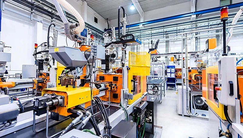
Qualità del refrigerante: Mantenere pulito il refrigerante per evitare ostruzioni e danni allo stampo.
Che cos’è la progettazione del sistema di scarico?
La progettazione del sistema di scarico è l’ingegnerizzazione di scanalature e fori di sfiato che consentono all’aria e ai gas intrappolati di fuoriuscire dalla cavità dello stampo durante l’iniezione.
Il sistema di sfiato espelle il gas dalla cavità dello stampo per evitare difetti come bolle e bruciature, che influiscono direttamente sulla qualità del prodotto e sulla durata dello stampo.
Scanalature di sfiato
La scanalatura di sfiato3 è un canale per la fuoriuscita dei gas ed è situata principalmente sulla linea di divisione.
Punti di progettazione: Posizionare le scanalature dove/quando il gas può accumularsi liberamente.
Punti di progettazione: Larghezza e profondità dovrebbero ottimizzare l’area della sezione trasversale per lo sfiato richiesto, in modo che non ci siano problemi durante l’espulsione della plastica.
Punti di progettazione: Distribuzione uniforme per prevenire problemi di sfiato localizzati.
Fori di sfiato
I fori di sfiato sono tra i componenti del sistema di sfiato che di solito si trovano nelle regioni sottili di un prodotto.
Punti di progettazione: Diametro appropriato per non ostacolare il rilascio dell’accumulo di gas garantendo al contempo un’adeguata evacuazione.
Punti di Progettazione: Il posizionamento non deve in alcun modo influenzare l’aspetto del prodotto né la sua resistenza.
Punti di progettazione: Quantità e posizione devono essere ragionevoli in base alla struttura dello stampo e alla forma del prodotto.
La progettazione del sistema di ventilazione deve tenere conto anche di:
Manutenzione del sistema: Dovrebbero essere puliti di tanto in tanto per garantire un flusso libero e senza ostacoli, ma controllati periodicamente per evitare ostruzioni che potrebbero causare problemi di qualità.
Raffreddamento del sistema: Nel caso di utilizzo di stampi ad alta temperatura, utilizzare mezzi di raffreddamento per evitare la condensazione dei gas durante lo sfiato.
Precisione di lavorazione: Alta precisione con superfici lisce per ridurre la resistenza al flusso di gas e la perdita di pressione.
ZetarMold lavora oltre 400 materiali plastici. I nostri 8 ingegneri senior supervisionano la qualità della lavorazione degli stampi sotto sistemi di gestione certificati ISO 9001, ISO 13485, ISO 14001 e ISO 45001.
Quali sono le lavorazioni dello stampo?
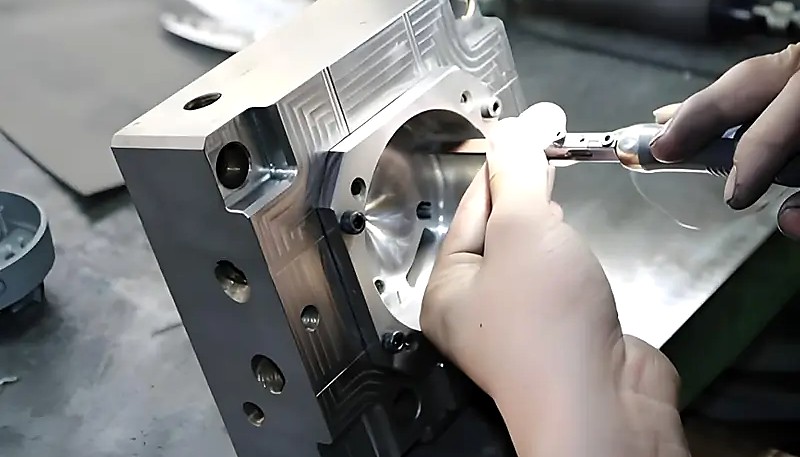
La lavorazione dello stampo è la serie di passaggi di lavorazione CNC, EDM, rettifica e trattamento superficiale che trasformano l’acciaio grezzo in uno stampo per iniezione di precisione.
"La corretta lavorazione dello stampo garantisce precisione dimensionale e qualità superficiale."True
La lavorazione CNC, l'EDM e il trattamento superficiale dei componenti dello stampo creano tolleranze precise e superfici lisce per una produzione costante dei pezzi.
"La lavorazione dello stampo è necessaria soltanto per gli stampi destinati alla produzione di grandi volumi."False
Tutti gli stampi richiedono una corretta lavorazione meccanica, trattamento termico e finitura superficiale, indipendentemente dal volume di produzione, per raggiungere le tolleranze richieste.
La lavorazione dello stampo è il processo di conversione del disegno progettuale nello stampo vero e proprio attraverso la lavorazione grezza, la lavorazione fine, il trattamento superficiale, ecc. L’analisi dimostra che l’accuratezza e la qualità della lavorazione influiscono direttamente sulla funzione e sulla durata dello stampo.
Lavorazione grezza
La lavorazione grezza viene eseguita sullo stampo a partire dal materiale grezzo e le attrezzature comunemente utilizzate sono la fresatura e il tornio CNC.
Punti Chiave: Lasciare un sufficiente margine per la finitura.
Punti chiave: La velocità e le velocità di avanzamento ottimali che aiutano a evitare la deformazione del materiale e l’usura graduale degli utensili e delle macchine.
Punti chiave: Lavorazione grezza per ridurre le sbavature e ottenere una superficie più liscia.
Finitura
La finitura realizza gli stampi per raggiungere le dimensioni e le specifiche dello stampo e utilizza il processo di rettifica, l’elettroerosione e la lucidatura.
Punti chiave: La precisione garantisce che la forma e le dimensioni siano corrette per lo stampo.
Punti Chiave: Evitare una lucidatura eccessiva per prevenire deviazioni dimensionali.
Punti chiave: Finitura della superficie con le attrezzature migliori e più appropriate per ottenere una finitura liscia e corretta.
Trattamento della superficie
Il trattamento della superficie dello stampo migliora la durezza e la resistenza all’usura, utilizzando i processi di tempra, nitrurazione e l’uso di un rivestimento superficiale.
Punti chiave: Selezionare metodi di trattamento appropriati in base al materiale dello stampo e all’applicazione.
Punti chiave: Per ridurre la deformazione e le crepe dello stampo, la durata del trattamento e la temperatura devono essere controllate.
Punti chiave: Pulire accuratamente prima del trattamento per una migliore adesione e prestazioni.
Come mantenere la muffa?
Una corretta manutenzione dello stampo è fondamentale per garantire una qualità costante e una lunga durata nello stampaggio a iniezione. Una cura regolare può evitare tempi di inattività e costose riparazioni.
La manutenzione dello stampo, sia quotidiana che periodica, ne prolunga la vita utile e riduce i costi di produzione attraverso una manutenzione costante.
Manutenzione ordinaria
Punti chiave: Assicurarsi che la superficie dello stampo sia pulita per evitare che temperature e polvere penetrino nello stampo.
Punti chiave: Lubrificare regolarmente la colonna guida e il bocchino guida per garantire la scorrevolezza del meccanismo di guida.
Punti chiave: Può essere necessario ispezionare spesso gli altri componenti dello stampo e ripararli o sostituirli tempestivamente.
Punti chiave: È necessario verificare se il canale di raffreddamento e il sistema di scarico sono normalmente aperti e se sono ostruiti; in caso di ostruzione, vanno sbloccati tempestivamente.
Manutenzione regolare
La manutenzione implica il controllo generale e la riparazione dello stampo dopo che è stato utilizzato per un certo periodo di tempo.
Punti chiave: Ispezionare la cavità e il nucleo dello stampo e individuare le parti della cavità che sono gravemente usurate, riparandole o sostituendole.
Punti chiave: verificare che meccanismo di guida, sistema di estrazione e altre parti dello stampo funzionino normalmente; eseguire le regolazioni o sostituzioni necessarie.
Punti chiave: verificare che il sistema di raffreddamento e il sistema di sfiato dello stampo funzionino normalmente ed eseguire le necessarie operazioni di pulizia e disostruzione.
Punti chiave: pulire e lubrificare accuratamente lo stampo per garantirne il corretto stato operativo.
Quali sono i problemi più comuni nella progettazione degli stampi e le loro soluzioni?
I problemi comuni nella progettazione degli stampi comprendono raffreddamento insufficiente, flusso del materiale disuniforme e posizionamento errato dei punti di iniezione, che compromettono la qualità del pezzo.
"La pulizia regolare prolunga la vita utile dello stampo e mantiene la qualità dei componenti."True
La manutenzione programmata, comprensiva di pulizia, lubrificazione e ispezione, previene usura, corrosione e deriva dimensionale durante i cicli produttivi.
"La manutenzione dello stampo non è necessaria se lo stampo è progettato correttamente."False
Tutti gli stampi richiedono pulizia e ispezione periodiche, indipendentemente dalla qualità del progetto, per mantenere la precisione dimensionale e prevenire l'usura progressiva.
Diversi problemi comuni possono incidere sulla qualità dei pezzi e sulla produttività se non vengono affrontati correttamente durante la progettazione dello stampo.
Segni di lavandino
Descrizione del problema: la superficie del prodotto è ammaccata e ne compromette l’aspetto.
Soluzione: si consiglia di definire posizione e dimensione del punto di iniezione in modo che possa accogliere il fuso e riempire uniformemente la cavità.
Soluzione: ottimizzare la progettazione e la disposizione del circuito di raffreddamento per garantire una distribuzione uniforme del raffreddamento ai prodotti.
Soluzione: regolare il tempo e la pressione di mantenimento per ridurre il ritiro del fuso.
Bava
Descrizione del problema: si formano sfridi nella zona periferica del prodotto, conferendogli un aspetto scadente e dimensioni potenzialmente imprecise.
Soluzione: nella progettazione della superficie di divisione, cercare di ridurre al minimo la chiusura dello stampo.
Soluzione: aumentare la forza di chiusura dello stampo per impedirne la separazione durante il processo di stampaggio a iniezione.
Soluzione: per controllare lo stampo, occorre anzitutto verificare il meccanismo di guida e il meccanismo di chiusura dello stampo.
Bolla
Descrizione del problema: sono presenti porosità visibili sulla superficie del prodotto o all’interno del prodotto stesso sotto forma di bolle, che ne compromettono l’aspetto e la durata.
Soluzione: ottimizzare il sistema di sfiato in modo da consentire l’efficace evacuazione del gas dalla cavità dello stampo.
Soluzione: regola i parametri utilizzati nell’iniezione, come la velocità e la forza di iniezione e la temperatura dei materiali da stampaggio a iniezione, per ridurre al minimo la generazione di gas.
Soluzione: controllare l’essiccazione delle materie prime per assicurarsi che il loro contenuto di umidità sia adeguato.
Deformazione e deformazione
Descrizione del problema: dopo il raffreddamento il pezzo stampato si ritira o deforma parzialmente, compromettendo stabilità dimensionale e finitura superficiale.
Soluzione: migliorare il raffreddamento per uniformare la temperatura di tutti i pezzi stampati.
Soluzione: regolare tempo e pressione di mantenimento nei parametri d’iniezione per ridurre le tensioni interne.
Soluzione: migliorare la struttura, ad esempio aggiungendo nervature per ottenere spessore uniforme.
Instabilità dimensionale
Descrizione del problema: la geometria non rispetta dimensioni e standard richiesti, compromettendo assemblaggio e utilizzo del prodotto.
Soluzione: esaminare la correttezza delle lavorazioni dello stampo e la realizzazione dell’assemblaggio dei prodotti per verificare se le dimensioni dello stampo sono conformi alle specifiche di progettazione per lo stampaggio a iniezione.
Soluzione: controllare i parametri di processo, quali la pressione di iniezione, il tempo di mantenimento della pressione e il tempo di raffreddamento, per garantire la stabilità dimensionale del prodotto.
Soluzione: confermare la stabilità produttiva delle presse a iniezione, così da poter determinare la variabilità dello stampaggio a iniezione.
Domande frequenti
Qual è il fattore più importante nella progettazione di uno stampo a iniezione?
Il fattore più critico nella progettazione di uno stampo a iniezione è ottenere uno spessore di parete uniforme in tutto il pezzo. Pareti non uniformi causano un raffreddamento differenziale, che determina direttamente risucchi, deformazioni e incoerenza dimensionale nel prodotto finito. Nella nostra esperienza presso ZetarMold con oltre 400 materiali, i pezzi con variazioni dello spessore di parete superiori al 15 percento richiedono quasi sempre costose rilavorazioni dello stampo per raggiungere una qualità accettabile. Oltre allo spessore di parete, il corretto posizionamento del punto di iniezione e una disposizione efficiente del sistema di raffreddamento sono altrettanto importanti nel determinare il tempo di ciclo e la durabilità a lungo termine dello stampo.
Quanto tempo occorre per progettare uno stampo a iniezione?
La progettazione di un tipico stampo a iniezione richiede da 2 a 4 settimane, in base alla complessità del pezzo. Stampi monocavità semplici per geometrie lineari possono richiedere solo da 5 a 7 giorni dal concetto ai disegni completati. Stampi multicavità complessi con movimenti laterali, sollevatori o meccanismi di svitamento possono richiedere da 4 a 6 settimane di progettazione. La fase comprende modellazione CAD 3D, simulazione del flusso per convalidare i percorsi di riempimento e più iterazioni di revisione. In ZetarMold, i nostri 8 ingegneri senior seguono un processo strutturato che individua tempestivamente i problemi.
Quale software viene usato per progettare stampi a iniezione?
I software standard del settore per la progettazione degli stampi a iniezione comprendono SOLIDWORKS e UG, noto anche come NX, per la modellazione CAD 3D, e Autodesk Moldflow per la simulazione del flusso e l’analisi termica. Questi strumenti consentono agli ingegneri di visualizzare la disposizione delle cavità, simulare i modelli di riempimento della plastica e ottimizzare il posizionamento dei canali di raffreddamento prima di lavorare l’acciaio. In ZetarMold, il nostro team di progettazione utilizza SOLIDWORKS, MOLDFLOW e CAD in combinazione per convalidare la posizione dei punti di iniezione, prevedere la posizione delle linee di giunzione e analizzare l’efficienza del raffreddamento, riducendo i difetti del primo articolo fino al 60 percento rispetto ai tradizionali metodi per tentativi ed errori.
Qual è il costo tipico di uno stampo a iniezione?
I costi degli stampi a iniezione variano notevolmente in funzione della complessità e dei requisiti produttivi. Gli stampi prototipali semplici, a cavità singola e in alluminio, partono da circa 1,000–3,000 dollari, mentre gli stampi di produzione in acciaio, con più cavità e sistemi a canale caldo, costano in genere tra 10,000 e 50,000 dollari. Gli stampi molto complessi con movimenti laterali, anime svitanti o finiture superficiali speciali possono superare 100,000 dollari. I principali fattori di costo comprendono il numero di cavità, il materiale dello stampo, il volume produttivo previsto, la qualità richiesta per la finitura superficiale e le specifiche di tolleranza dell’applicazione.
Come si previene la bava nella progettazione degli stampi a iniezione?
La prevenzione delle bave inizia con una progettazione precisa della superficie di divisione e il corretto calcolo della forza di chiusura. La linea di divisione dello stampo deve essere lavorata con tolleranze di planarità entro 0,01 millimetri per garantire la chiusura completa sotto la pressione di iniezione. Le scanalature di sfiato devono avere una profondità corretta di 0,01-0,03 millimetri, così da far uscire il gas intrappolato senza consentire al materiale fuso di filtrare. La pressa deve disporre di tonnellaggio sufficiente. In ZetarMold, le nostre 47 presse vanno da 90T a 1850T, consentendo di abbinare con precisione la capacità della macchina a ogni stampo.
Qual è la differenza tra uno stampo a canale freddo e uno a canale caldo?
Uno stampo a canale freddo convoglia la plastica fusa attraverso passaggi non riscaldati, generando materozze solidificate da separare, rimacinare e riciclare o smaltire. Uno stampo a canale caldo usa collettori riscaldati elettricamente per mantenere fusa la plastica nei canali di distribuzione, eliminando completamente le materozze e riducendo il ciclo. Gli stampi a canale caldo costano inizialmente il 20-40% in più per collettore e termoregolatori, ma nelle produzioni ad alto volume consentono un risparmio di materiale del 15-30% e migliorano la costanza.
Quale tolleranza può raggiungere lo stampaggio a iniezione?
Lo stampaggio a iniezione standard raggiunge tolleranze di più o meno 0.1 millimetri per dimensioni inferiori a 25 millimetri. Lo stampaggio di precisione, con controllo di processo ottimizzato, regolazione rigorosa della temperatura e stampi di alta qualità, può raggiungere più o meno 0.05 millimetri o tolleranze più strette per le caratteristiche critiche. La capacità di tolleranza dipende fortemente dalle caratteristiche di ritiro del materiale, poiché i materiali semicristallini presentano una variabilità maggiore rispetto a quelli amorfi. Per applicazioni con tolleranze strette, gli ingegneri ZetarMold utilizzano la simulazione Moldflow durante la fase di progettazione per prevedere e compensare il ritiro prima della costruzione dello stampo.
Perché la progettazione dello stampo a iniezione è importante per il successo della produzione?
La progettazione dello stampo a iniezione è il fattore più importante per la qualità dei componenti, l’efficienza produttiva e il controllo dei costi nella produzione di plastica.
Questo articolo fornisce riferimenti pratici per i progettisti di stampi a iniezione. Per assistenza nella progettazione di stampi personalizzati, contattate ZetarMold per ricevere supporto specialistico.
Scoprite lo stampaggio a iniezione: una guida completa: lo stampaggio a iniezione è un processo produttivo nel quale la plastica fusa viene iniettata in uno stampo per creare pezzi con elevata precisione e ripetibilità. ↩
Scoprite che cosa sono anima e cavità nello stampaggio a iniezione. La cavità e l’anima di un tipico stampo per una pressa a iniezione per materie plastiche sono le parti dello stampo che formano il componente. ↩
Scopri Tipi di punti di iniezione per lo stampaggio a iniezione: guida completa alla progettazione: un punto di iniezione è un’apertura progettata, generalmente piccola, che controlla il flusso della plastica fusa nella cavità dello stampo. ↩
Informazioni sull’acciaio per utensili H13: H13 è un acciaio per lavorazioni a caldo con buona resistenza alla fatica termica, all’erosione e all’usura, ampiamente utilizzato per realizzare stampi e matrici. ↩
Scoprite quattro principi importanti da considerare nella progettazione dello spessore delle pareti: lo spessore delle pareti dei prodotti plastici è una caratteristica strutturale critica, spesso discussa e valutata nella progettazione delle strutture dei prodotti plastici. ↩
Scoprite come determinare la pressione e il tempo di mantenimento nello stampaggio a iniezione. La pressione di iniezione comprende sia la pressione sia la velocità. ↩
Richiedi prezzi competitivi, feedback DFM e tempistiche di produzione al team tecnico di ZetarMold.
Richiedete un preventivo gratuito →
Acciaio P20: la norma ASTM A681 specifica gli acciai legati per utensili, incluso il P20, con durezza tipica di 28-36 HRC per applicazioni nei portastampi. ↩
canali di raffreddamento: secondo le ricerche di ingegneria dei polimeri, il raffreddamento può rappresentare fino al 70% del tempo totale del ciclo di stampaggio a iniezione. ↩
scanalatura: per la maggior parte dei materiali termoplastici, la profondità standard delle scanalature di sfiato varia da 0.01 a 0.03 mm, consentendo la fuoriuscita dei gas senza formazione di bava. ↩