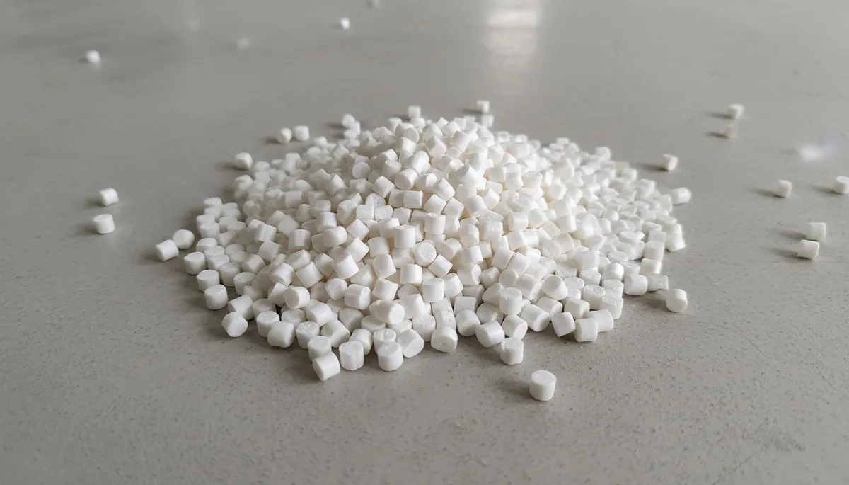
Bir enjeksiyon kalıbı tasarlamak; en iyi sonuçları ve yüksek üretim verimliliğini elde etmek için malzeme seçimi, kalıp boşluğu yerleşimi ve parça geometrisi gibi birkaç temel adımı içerir.
Kalıp tasarım ilkelerini anlamak, verimli üretim ve yüksek kaliteli çıktı için gereklidir. İster yeni bir kalıp tasarlıyor ister mevcut bir takımı optimize ediyor olun, bu faktörler kalıp performansını, çevrim süresini ve üreticilerin toplam maliyet tasarrufunu doğrudan etkiler.
- Kalıp malzemesi seçimi (çelik veya alüminyum), takım ömrünü ve parça kalitesini doğrudan etkiler
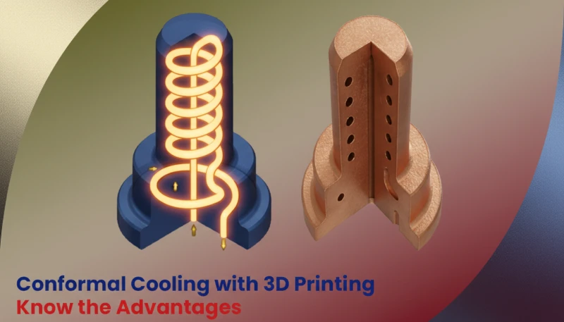
- Doğru soğutma kanalı yerleşimi çevrim süresini 70% oranına kadar azaltabilir
- Eşit et kalınlığı en kritik tasarım faktörüdür
- 0.01–0.03 mm havalandırma kanalı derinliği gaz çıkışına izin verirken çapaklanmayı önler
- Düzenli kalıp bakımı takım ömrünü uzatır ve boyutsal doğruluğu korur
Enjeksiyon Kalıplarının Temel Prensipleri Nelerdir?
Enjeksiyon kalıpları, erimiş malzemenin bir kalıp boşluğuna enjekte edildiği bir süreç kullanarak yüksek hassasiyetli parçalar üretmek için gereklidir. Bu teknoloji birçok endüstrinin temelini oluşturmakta, hızlı ve tutarlı üretim sağlamaktadır.
Tedarikçileri karşılaştırıyor veya satın alma planlıyorsanız enjeksiyon kalıplama tedarikçisi bulma kılavuzumuz RFQ hazırlığını, yeterlilik değerlendirmesini ve ticari risk kontrollerini ele alır.
Enjeksiyon kalıplama sürecinde erimiş malzeme yüksek basınçla kalıp boşluğuna enjekte edilir ve burada katılaşarak istenen ürünü oluşturur. Kalıp tasarımı, ürünün kolayca çıkarılmasını ve beklenen ölçülere çok yakın olmasını sağlar.
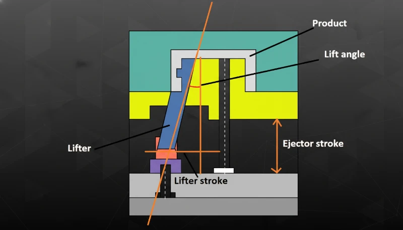
Enjeksiyon kalıplarının malzemeleri, yapısı ve yerleşimi nihai ürünün kalitesi, verimliliği ve maliyetiyle doğrudan ilişkilidir.
Enjeksiyon kalıp tasarımının temel ilkeleri birkaç kilit aşama içerir
Erimiş plastiğin hazırlanması ilk aşamadır. Plastik ham madde, vidanın kesme etkisi ve ısıtıcı aracılığıyla eritilir.
Enjeksiyon: Erimiş plastik, vidanın uyguladığı basınç yardımıyla memeden kalıp gözüne zorlanır.
20 yılı aşkın enjeksiyon kalıbı tasarımı deneyimine sahip ZetarMold, Şanghay fabrikamızda 47 enjeksiyon kalıplama makinesi (90T–1850T) çalıştırmakta ve neredeyse her boyut ve karmaşıklıktaki parçanın kalıp tasarımını gerçekleştirmektedir.
Ütüleme Basıncı ve Soğutma: Enjeksiyon kalıplama makinesi, kavitenin dolmasını sağlamak için bu basıncı bir süre korur; ardından plastik katılaşmaya başlarken soğutma prosesini başlatır.
Plastik katılaştıktan sonra kalıp açılır ve genellikle pim, plaka veya kovanlardan oluşan çıkarma sistemi bitmiş parçayı kaviteden dışarı iter. Doğru çıkarma tasarımı, parçanın deforme olmadan veya kritik yüzeyleri zarar görmeden temiz biçimde ayrılmasını sağlar.
"Doğru kalıp tasarımı kusurları azaltır ve üretim verimliliğini artırır."True
İyi tasarlanmış enjeksiyon kalıpları, üretim serileri boyunca tutarlı parça kalitesi, daha düşük hurda oranları ve daha kısa çevrim süreleri sağlar.
"Enjeksiyon kalıbı tasarımı yalnızca ürün şekliyle ilgilidir."False
Kalıp tasarımı ayrıca verimli üretim için malzeme seçimini, soğutma sistemi yerleşimini, çıkarma mekanizmalarını ve proses optimizasyonunu kapsar.
Kalıp Malzemeleri Nelerdir?
Kalıp malzemeleri, enjeksiyon kalıplama gibi üretim süreçlerinde dayanıklılık, hassasiyet ve kalite sağlamak açısından temel öneme sahiptir. Malzeme seçimi, üretim verimliliğini ve nihai ürünün özelliklerini etkiler.
Kalıp malzemesi seçimi, kalıbın hizmet ömrü ve bitmiş ürünün kalitesi üzerinde büyük bir etkiye sahiptir. Yaygın kalıp malzemeleri çelik ve alüminyumdur.
Çelik
Çelik kalıplar alüminyuma göre üstün sertlik, aşınma direnci ve ısıl işlem özellikleriyle çok daha uzun çalışma ömrü sunar; bu da onları ölçü tutarlılığının kritik olduğu yüksek hacimli üretim için ideal kılar.
Çelik kalıpların başlıca dezavantajları, alüminyuma göre daha uzun işleme süreleri ve daha yüksek malzeme maliyetleridir. Çelik ayrıca belirgin ölçüde daha ağırdır; bu da taşımayı zorlaştırır ve kalıp değiştirme ekipmanındaki aşınmayı artırır. Ancak yüksek hacimli uygulamalarda daha uzun takım ömrü genellikle bu dezavantajları dengeler.
Yaygın Çelikler:
P20 Çeliği1, kalıp tabanlarında ve büyük boşluklarda yaygın kullanılan çok yönlü, ön sertleştirilmiş bir kalıp çeliğidir (28-36 HRC). Orta adetli üretim kalıpları için uygun maliyetle mükemmel işlenebilirlik ve parlatılabilirlik sunar.
H13, yüksek sıcaklıklarda çalışan kalıplar için sıcak iş takım çeliğidir. Uzun süre ısıya maruz kaldıktan sonra sertliğini ve ısıl kararlılığını korur; işlem sonrası tipik sertliği 44–52 HRC’dir.
S136, mükemmel korozyon direncine ve parlatılabilirliğe sahip paslanmaz bir takım çeliğidir. Yüzey kalitesinin son derece önemli olduğu optik lensler, şeffaf parçalar ve medikal kalıplar için tercih edilen seçenektir.
Alüminyum
Alüminyum kalıplar önemli ölçüde ağırlık tasarrufu ve çeliğe göre yaklaşık 4–5x daha iyi ısıl iletkenlik sağlayarak daha hızlı soğutmaya ve daha kısa çevrim sürelerine imkân verir. Kolay işlenebilirlik takım teslim süresini ve maliyetini azaltır; bu da alüminyumu prototipleme ve düşük hacimli üretim için ideal kılar.
Başlıca dezavantajı, daha düşük sertlik ve aşınma direncidir; bu da alüminyum kalıpları aşındırıcı reçinelerin neden olduğu yüzey hasarına açık hâle getirir. Takım hazırlama hızının uzun ömürden daha önemli olduğu, 10,000–50,000 parçanın altındaki üretim serileri için en uygunudur.
Ortak Alüminyum:
7075, en dayanıklı alüminyum sınıflarından biridir (çekme dayanımı ~570 MPa). Buna rağmen sertliği takım çeliğinin çok altında kaldığından prototip kalıplar ve kısa üretim serileri için en uygundur.
Kalıp Yapı Tasarımı Temelde Neleri İçerir?
Kalıp yapısı tasarımı, yüksek kaliteli enjeksiyon kalıpları oluşturmanın anahtarıdır ve kalıplama işlemi sırasında verimlilik ve tutarlılık sağlar. Kalıp akışı, soğutma ve malzeme uyumluluğu gibi kritik hususları içerir.
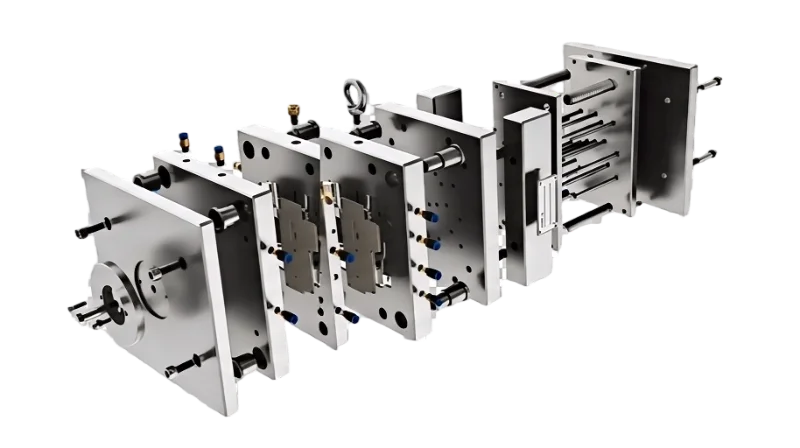
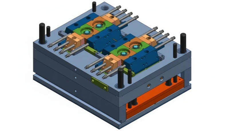
Kalıp yapısı tasarımı; boşluk, maça, çerçeve, yolluk girişi, kılavuz ve geri çekme sistemini ifade eder. Uygun verimlilik, sağlamlık ve kolay bakım için bunların tümü dikkatle tasarlanmalıdır.
Boşluk ve Çekirdek
Boşluk, ürünün dış boyutlarını oluştururken çekirdek, nihai ve istenen ürün şeklini ve boyutunu sağlamak için birbirine bağlanan iç boyutları verir.
Malzeme Seçimi: Genellikle P20 veya H13 çeliği gibi yüksek sertlikte ve aşınmaya dayanıklı çelikler kullanılır.
Tasarım Noktaları: Ürünün yüzey kalitesinde yüksek boyutsal doğruluğu korumak için boşluğun ve maçanın işlenmiş yüzeyleri pürüzsüz olmalıdır.
Kalıp Tabanı
Kalıp tabanı aynı zamanda aletin iskelet iskeletidir ve tüm bileşenleri sabitleme ve bağlama görevine sahiptir. Kalıpların montajına ve gerektiğinde değiştirilmesine izin vermek için genellikle standart bir forma sahiptir.
Malzeme Seçimi: Kalıp tabanının kararlılığını güvenceye almak için genellikle kalıp tabanında 45 steel veya Q235 steel kullanılır.
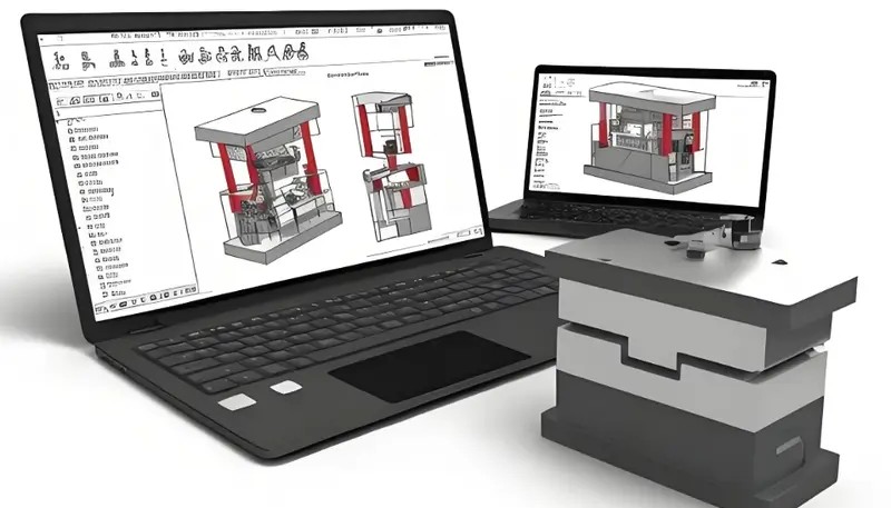
ZetarMold bünyesindeki kalıp üretim tesisimiz, işleme başlamadan önce kalıp akışını simüle etmek ve soğutma tasarımlarını doğrulamak için UG, SOLIDWORKS, MOLDFLOW ve CAD kullanarak ayda 100'den fazla kalıp seti üretir.
"Kalıp yapısı tasarımı, parça kalitesini ve üretim verimliliğini doğrudan etkiler."True
Doğru kalıp gözü yerleşimi, soğutma kanalı konumu ve itici sistem tasarımı; boyutsal doğruluğu, çevrim süresini ve kusur oranlarını belirler.
"Uygulamadan bağımsız olarak tüm kalıp yapıları aynıdır."False
Kalıp yapıları; parça geometrisine, malzeme özelliklerine, üretim hacmine ve sektöre özgü gereksinimlere bağlı olarak önemli ölçüde değişir.
Tasarım Noktaları: Kalıp tabanı; enjeksiyon basıncına, enjeksiyon sıcaklığına ve enjeksiyon sırasındaki genel ileri geri basınca dayanacak yeterli mukavemet ve rijitliğe sahip olmalıdır.
Yolluk Sistemi
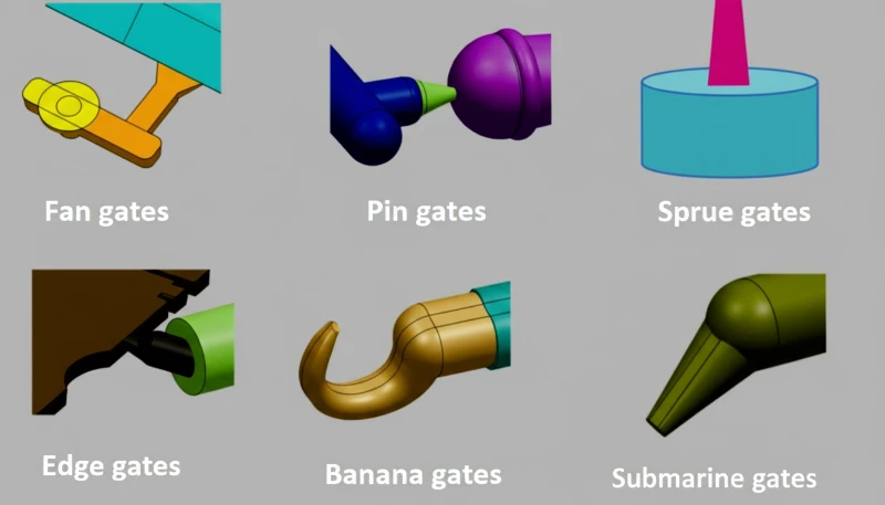
Yolluk sistemi birincil yolluk, alt yolluklar ve erimiş plastiğin boşluğa yönlendirildiği kapılardan oluşur. Etkili bir yolluk sistemi, kalıplama kalitesinin artırılmasına ve kullanılan malzeme miktarının azaltılmasına yardımcı olur.
Tasarım Noktaları: Basınç kaybını ve kesilmeleri mümkün olduğunca azaltmak için ana yolluk olabildiğince kısa ve düz olmalıdır.
Tasarım Noktaları: Tali yolluklar, her göz boşluğuna eşit miktarda malzeme sağlayacak şekilde düzenlenmelidir.
Tasarım Noktaları: Yolluk girişinin niteliği, ürünün görünümünü hiçbir şekilde etkilememeli veya dayanımından ödün vermemelidir. Kullanılan yolluk girişinin boyutu uygun olmalıdır.
Yönlendirme Mekanizması
Kılavuz mekanizması, hareketli ve sabit kalıplar arasında hizalamaya yardımcı olan kılavuz pimleri ve burçları içerir.
Malzeme Seçimi: Genellikle GCr15 gibi yüksek sertlikte çelik kullanılır.
Tasarım Noktaları: Kılavuz mekanizması, aşınmaya karşı son derece dayanıklı olmasının yanı sıra uzun süre boyunca hizasızlığı önleyecek ölçüde hassas hizalama sağlamalıdır.
Fırlatma Mekanizması
Çıkarma parçası, kalıplanmış ürünü kalıptan çıkarmak için uygulanır ve normalde çıkarma pimleri, plakaları ve manşonları kullanılır.
Tasarım Noktaları: Bu kuvvet için bir diğer gereklilik, ani kuvvet ürünü olumsuz etkileyebileceğinden sabit veya yumuşak olmasıdır. Yapışmayı önlemek için çıkarma mekanizmasının hareketi de yumuşak olmalıdır.
Akış Kanalı Tasarımı Nedir?
Akış kanalı tasarımı; erimiş plastiği makine memesinden kalıp boşluğuna yönlendiren sprue, yolluklar ve yolluk girişlerinin mühendisliğidir.
Yolluk tasarımı ürün kalitesini ve üretim verimliliğini önemli ölçüde etkiler. Yolluğun boyutu ve şekli, malzeme ve parça geometrisine uygun olmalıdır.
Ana Koşucu
Ana yolluk, enjeksiyon makinesi memesini alt yolluklara bağlar ve basınç kaybını ve malzeme israfını azaltmak için mümkün olduğunca kısa ve düz olmalıdır.
Tasarım Noktaları: Ana yolluk çapı, yeterli akışı sağlarken gereksiz malzeme kullanımını azaltacak şekilde doğru belirlenmelidir.
Alt Koşucular
Alt raylar plastik eriyiği kalıbın her bir boşluğuna dağıtır ve burada denge önemli bir husus olmalıdır.
Tasarım Noktaları: Akış direncini azaltmak için tali yolluk kesitleri tercihen dairesel veya yarı dairesel olmalıdır. Tüm kavitelerin dolum sürelerinin yaklaşık eşit olması için yolluk uzunlukları olabildiğince eşit tasarlanmalıdır.
Yolluk girişleri
Kapılar, boşluğa verilen erimiş plastiğin ürün kalitesini etkilediği araçlardır.
Tasarım Noktaları: Yolluk girişleri görünümü veya dayanımı etkilemeyen alanlara yerleştirilmelidir. Boyutları, kolayca ayrılabilirken yeterli dolum hızını sağlamalıdır. Farklı giriş tipleri, farklı ürün gereksinimlerine hizmet eder.
Ek olarak, yolluk tasarımı aşağıdakileri dikkate almalıdır:
Runner Dengesi: Çoklu boşluklar için runner uzunlukları ve kesit alanlarının kalıp dolum zamanının ana belirleyicisi olduğundan emin ol.
Yolluk Soğutma: Yüksek sıcaklığın eriyik akışını etkilememesi için yolluk bölümünde yeterli soğutma kanalları2 bulunmalıdır.
Runner Hassasiyeti: İşleme hassasiyeti yüksek ve yüzey pürüzsüz, eriyik akışına ve basınç düşüşüne engeli azaltmak için.
Soğutma Sistemi Tasarımı Nedir?
Soğutma sistemi tasarımı, üretim süreçlerini optimize etmede, tutarlı ürün kalitesi ve üretim döngülerinde verimlilik sağlamada çok önemlidir.
"Akış kanalı tasarımı, kalıplama verimliliğini ve parça kalitesini önemli ölçüde etkiler."True
Optimize runner ve gate geometrisi malzeme israfını azaltır, döngü zamanını kısaltır ve boşluklar arası dolum tutarlılığını iyileştirir.
"Akış kanalı tasarımı tüm kalıp türleri ve malzemeler için aynıdır."False
Akış kanalı geometrisi, optimum dolum desenleri için malzeme viskozitesi, parça kalınlığı, geçit tipi ve boşluk düzenine göre özelleştirilmelidir.
Soğutma sistemi, enjeksiyon kalıplama döngü süresini ve kalıp kalitesini azalttığı için enjeksiyon kalıbı tasarımında çok önemli bir rol oynar. Soğutma sistemi büyük ölçüde soğutma kanallarını ve soğutma süresi aşamalarını içerir.
Soğutma Kanalları
Soğutma kanalları, fazla ısıyı uzaklaştırmak için soğutma suyunu çeşitli kalıp parçaları boyunca yönlendirir.
Soğutma kanalları, ısı dağılımını en üst düzeye çıkarmak için olabildiğince boşluk yüzeyine yakın konumlandırılmalıdır. Kanal çapının 1,5–2,5 katı bir kanal-boşluk mesafesi, soğutma performansı ile kalıp çeliğinin yapısal bütünlüğünü dengeler.
Soğutucu akışı, yerel ısı noktalarını önlemek için tüm kanallarda eşit olarak dağıtılmalıdır. Dengesiz soğutma, bitmiş parçada farklı büzülme, iç stresler ve eğrilme yol açır. Bafflelar veya spiral ekler, akışın kalıpın az servis alan bölgelerine yönlendirilmesine yardımcı olabilir.
Kanal çapı, aşırı basınç düşüşü yaratmadan yeterli soğutucu akış hızını (genellikle 1,5–3 m/s) korumak için yeterince büyük olmalıdır. Çok küçük çaplar, kireç veya kalıntılardan tıkanma riski taşırken, aşırı büyük kanallar akış türbülansını ve ısı transfer verimliliğini azaltır.
Soğutma Süresi
Soğutma süresi ayrıca ürünün duvar kalınlıklarına, kullanılan malzeme tipine ve kalıp sıcaklıklarına bağlıdır.
Yeterli soğutma zamanı eğrilme ve büzülmeyi önlerken boyutsal stabiliteyi sağlar. Optimum süre, parça sağlamlığı ile üretim hızını dengeler — çoğu enjeksiyon kalıplama operasyonunda toplam döngü zamanının tipik olarak 60–80%‘i.
Soğutma sistemleri için dikkate alınması gereken diğer hususlar şunlardır:
Soğutucu akış hızı dikkatli kontrol gerektirir. Düşük hız soğutma verimliliğini azaltabilirken, yüksek hız tıkanma ve kalıp aşınmasına yol açabilir.
Soğutucu Isısı: Optimum ısı, yüksek ısı soğutma hızını azaltırken düşük ısı kalıp yüzeyinde yoğunlaşma yapar ve ürün kalitesini etkileyebilir.
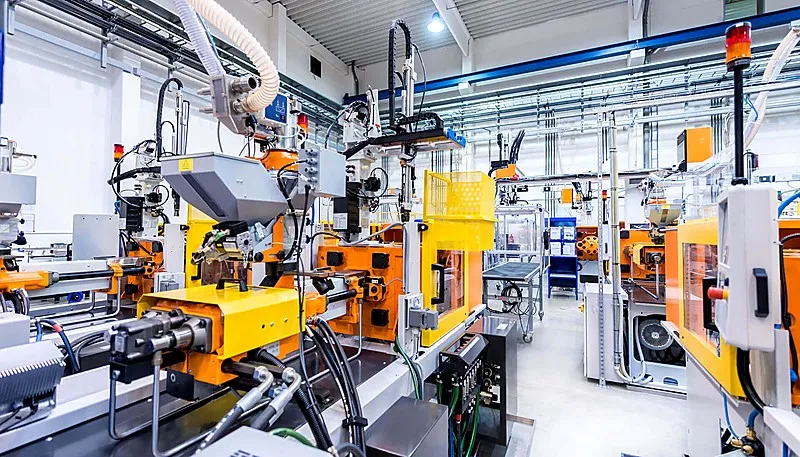
Soğutucu Kalitesi: Tıkanmaları ve kalıp hasarını önlemek için soğutucuyu temiz tutun.
Egzoz Sistemi Tasarımı Nedir?
Havalandırma sistemi tasarımı, enjeksiyon sırasında kalıp boşluğunda kalan hava ve gazların kaçmasını sağlayan havalandırma kanalları ve deliklerin mühendisliğidir.
Havalandırma sistemi, ürün kalitesini ve kalıp ömrünü doğrudan etkileyen kabarcıklar ve yanıklar gibi kusurları önlemek için kalıp boşluğundan gazı dışarı atar.
Havalandırma Olukları
Havalandırma oluğu3 gazın dışarı çıkmasını sağlayan bir kanaldır ve çoğunlukla ayırma çizgisinde bulunur.
Tasarım Noktaları: Gaz serbestçe birikebilecek yerlerde/zamanlarda yer kanalları yerleştir.
Tasarım Noktaları: Genişlik ve derinlik, plastik çıkarma tarafında sorun yaşanmaması için gerekli havalandırma için kesit alanını optimize etmelidir.
Tasarım Noktaları: Yerel havalandırma sorunlarını önlemek için eşit dağılım.
Havalandırma Delikleri
Havalandırma delikleri, normalde bir ürünün ince bölgelerinde bulunan havalandırma sisteminin bileşenleri arasındadır.
Tasarım Noktaları: Gaz birikiminin tahliyesini engellememek için uygun çap, aynı zamanda doğru havalandırma garantisi.
Tasarım Noktaları: Pozisyonlama hiçbir şekilde ürünün görünümünü ve dayanımını etkilememeli.
Tasarım Noktaları: Miktar ve konum, kalıbın yapısı ve ürünün şekli ile makul olmalıdır.
Havalandırma sistemi tasarımı da dikkate alınmalıdır:
Sistem Bakımı: Tıkanıklıkların kalite sorunlarına yol açmasını önlemek için araçları kontrol edin ve akışın engellenmemesi için zaman zaman temizlenmelidir.
Sistem Soğutma: Yüksek ısı kalıplar kullanıldığında, gazların havalandırma zamanında yoğunlaşmasını önlemek için soğutma araçlarından faydalan.
İşleme Hassasiyeti: Gaz akış direncini ve basınç kaybını azaltmak için pürüzsüz yüzeylerle yüksek hassasiyet.
ZetarMold, 400'den fazla plastik malzemeyi işler. 8 kıdemli mühendisimiz, ISO 9001, ISO 13485, ISO 14001 ve ISO 45001 sertifikalı yönetim sistemleri kapsamında kalıp işleme kalitesini denetler.
Kalıp İşlemleri Nelerdir?
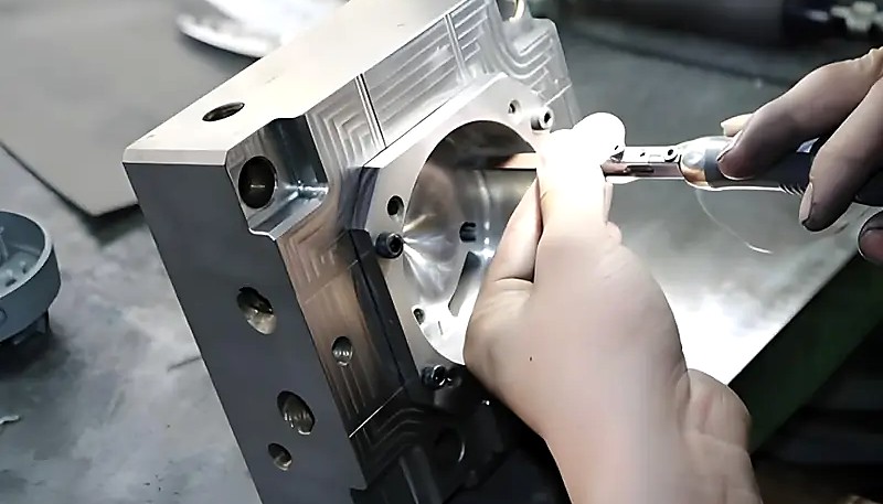
Kalıp işleme, ham çeliği hassas bir enjeksiyon kalıba dönüştüren CNC işleme, EDM, taşlama ve yüzey işlem adımları serisidir.
"Doğru kalıp işleme, ölçü doğruluğu ve yüzey kalitesi sağlar."True
Kalıp bileşenlerinin CNC işleme, EDM ve yüzey işlemi, tutarlı parça üretimi için hassas toleranslar ve pürüzsüz yüzeyler oluşturur.
"Kalıp işleme yalnızca yüksek hacimli üretim kalıpları için gereklidir."False
Tüm kalıplar, gereken toleransları elde etmek için üretim hacmi ne olursa olursa, uygun işleme, ısıl işlem ve yüzey bitirme gerektirir.
Kalıp işleme, tasarım çiziminin kaba işleme, ince işleme, yüzey işleme vb. yoluyla gerçek kalıba dönüştürülmesi sürecidir. Analiz yoluyla, işleme doğruluğu ve kalitesinin kalıbın işlevini ve dayanıklılığını doğrudan etkilediği görülebilir.
Kaba İşleme
Hammaddeden kalıp üzerinde kaba işleme yapılır ve kullanılan yaygın ekipman CNC freze ve tornadır.
Önemli Noktalar: Bitirme işlemi için yeterli pay bırakın.
Önemli Noktalar: Malzemenin deformasyonunu ve araçların/makinelerin kademeli aşınmasını önlemeye yardımcı olan optimum hız ve ilerleme oranları.
Anahtar Noktalar: Talaşı azaltmak için kaba işleme ve daha pürüzsüz yüzey elde etmek.
Bitirme
Son işlem, kalıbın boyutuna ve özelliklerine ulaşmak için yapılır ve taşlama işlemi, EDM ve parlatma kullanır.
Önemli Noktalar: Kalıbın şekil ve boyutunun doğru olduğundan emin olmak için hassasiyet.
Anahtar Noktalar: Boyutsal sapmaları önlemek için fazla polisajdan kaçın.
Önemli Noktalar: Pürüzsüz ve uygun bir bitiş elde etmek için yüzeyi en iyi ve en uygun ekipmanla bitirin.
Yüzey İşlemleri
Kalıp yüzey işlemi, su verme, nitrürleme ve yüzey kaplama işlemlerinin kullanıldığı kalıp sertliğini ve aşınma direncini artırır.
Önemli Noktalar: Kalıp malzemesi ve uygulamaya bağlı olarak uygun işlem yöntemlerini seçin.
Önemli Noktalar: Kalıp deformasyonunu ve çatlakları azaltmak için işlem süresi ve sıcaklık kontrol edilmelidir.
Önemli Noktalar: Daha iyi yapışma ve performans için işlemden önce iyice temizleyin.
Küfün Bakımı Nasıl Yapılır?
Enjeksiyon kalıplamada tutarlı kalite ve uzun ömürlülük sağlamak için uygun kalıp bakımı çok önemlidir. Düzenli bakım, duruş sürelerini ve maliyetli onarımları önleyebilir.
Kalıp bakımı, hem günlük hem periyodik, servis ömrünü uzatır ve tutarlı bakım ile üretim maliyetlerini azaltır.
Rutin Bakım
Önemli Noktalar: Kalıp yüzeyinin mümkün olduğunca temiz olmasını sağlayarak sıcaklıkların ve tozun kalıba nüfuz etmesini önleyin.
Önemli Noktalar: Kılavuz pimi ve kılavuz burcunu düzenli olarak yağlayarak kılavuz mekanizmasının esnekliğini sağlayın.
Anahtar Noktalar: Kalıpın diğer bileşenlerini sıkça kontrol etmek ve zamanında onarmak veya değiştirmek gerekliliği olabilir.
Önemli Noktalar: Soğutma kanalı ve egzoz sisteminin normalde açık olup olmadığını ve tıkanıp tıkanmadığını doğrulamak gerekir, eğer tıkanmışlarsa zamanında temizlenmelidir.
Düzenli Bakım
Bakım, bir süre kullanıldıktan sonra kalıbın genel kontrolü ve onarımı anlamına gelir.
Önemli Noktalar: Kalıp boşluğunu ve çekirdeği kontrol edin ve ciddi şekilde aşınmış boşluk kısmını bulun ve onları onarın veya değiştirin.
Önemli Noktalar: Kılavuz mekanizmasının, kalıptan çıkarma mekanizmasının ve kalıbın diğer parçalarının normal çalışıp çalışmadığını kontrol edin; gerekli ayarları veya değişimleri yapın.
Önemli Noktalar: Kalıbın soğutma ve gaz tahliye sistemlerinin normal çalışıp çalışmadığını kontrol edin; gereken temizlik ve açma işlemlerini yapın.
Temel Noktalar: Kalıbın iyi çalışır durumda olmasını sağlamak için kalıbı iyice temizleyin ve yağlayın.
Kalıp Tasarımında Sık Karşılaşılan Sorunlar ve Çözümleri Nelerdir?
Yaygın kalıp tasarımı sorunları arasında parça kalitesini etkileyen yetersiz soğutma, düzensiz malzeme akışı ve hatalı giriş konumu bulunur.
"Düzenli temizlik kalıp ömrünü uzatır ve parça kalitesini korur."True
Temizlik, yağlama ve muayeneyi içeren planlı bakım; üretim çevrimleri boyunca aşınmayı, korozyonu ve boyutsal sapmayı önler.
"Kalıp doğru tasarlanmışsa kalıp bakımı gereksizdir."False
Boyutsal doğruluğu korumak ve ilerleyici aşınmayı önlemek için tasarım kalitesinden bağımsız olarak tüm kalıplar düzenli temizlik ve inceleme gerektirir.
Kalıp tasarımı sırasında doğru şekilde ele alınmazsa çeşitli yaygın sorunlar parça kalitesini ve üretim hızını etkileyebilir.
Lavabo İşaretleri
Sorun Açıklaması: Ürün yüzeyindeki çöküntü görünümü olumsuz etkiler.
Çözüm: Girişin konumu ve boyutu, eriyiği kabul ederek kaviteyi eşit biçimde dolduracak şekilde seçilmelidir.
Çözüm: Soğutmanın ürünlere eşit dağılmasını sağlamak için soğutma devresi tasarımını ve düzenini en üst düzeye çıkarın.
Çözüm: Eriyik büzülmesini azaltmak için tutma süresini ve basıncını ayarlayın.
Flaş
Sorun Açıklaması: Ürünün çevresinde oluşan fire kötü bir görünüme yol açar ve boyutların doğruluğunu bozabilir.
Çözüm: Kalıbın ayırma yüzeyi tasarımında kalıbı mümkün olan en az açıklıkla kapatmaya çalışın.
Çözüm: Enjeksiyon kalıplama üretim sürecinde kalıbın ayrılmasını önlemek için kalıbın sıkma kuvvetini artırın.
Çözüm: Kalıbı kontrol etmek için önce kalıbın kılavuz mekanizması ve bağlama mekanizması kontrol edilmelidir.
Baloncuk
Sorun Açıklaması: Ürünün gövdesinde veya ürünün içinde görünüm ve dayanıklılığı etkileyen kabarcık biçiminde gözenekler vardır.
Çözüm: Kalıp gözündeki gazın etkili biçimde tahliye edilmesini sağlayacak şekilde egzoz sistemi tasarımını mümkün olduğunca sadeleştirin.
Çözüm: Gaz oluşumunu en aza indirmek için enjeksiyon hızı, enjeksiyon kuvveti ve enjeksiyon kalıplama malzemelerinin sıcaklığı gibi enjeksiyonda kullanılan parametreleri ayarlayın.
Çözüm: Ham maddelerin nem içeriğinin uygun düzeyde olduğundan emin olmak için kurutma işlemini kontrol edin.
Deformasyon ve Eğrilme
Sorun Açıklaması: Enjeksiyonla kalıplanmış parça soğuduktan sonra kısmen çeker veya deforme olur; ürünün boyutsal kararlılığı ve yüzey kalitesi bozulur.
Çözüm: Tüm enjeksiyon kalıplı parçalarda olabildiğince eşit sıcaklık sağlamak için soğutma sistemini iyileştirin.
Çözüm: İç gerilimi azaltmak için enjeksiyon parametrelerinde ayarlanan tutma süresini ve tutma basıncını düzenleyin.
Çözüm: Üründe eşit ve tutarlı cidar kalınlığı sağlamak için takviye nervürleri eklemek gibi kalıp yapısı tasarımı değişikliklerini güçlendirin.
Boyutsal Kararsızlık
Sorun Tanımı: Geometri, ürünün montajını ve kullanımını etkileyecek şekilde gerekli ölçü ve standartların dışındadır.
Çözüm: Kalıp ölçülerinin enjeksiyon kalıplama tasarım spesifikasyonlarına uygun olup olmadığını doğrulamak için kalıbın doğru işlenmesini ve ürün montajının gerçekleşmesini inceleyin.
Çözüm: Ürün boyutunun kararlı olması için enjeksiyon basıncı, tutma basıncı süresi ve soğutma süresi gibi proses parametreleri kontrol edilmelidir.
Çözüm: Enjeksiyon kalıplamadaki değişimi belirleyebilmek için enjeksiyon makinelerinin üretim kararlılığını doğrulayın.
Sıkça Sorulan Sorular
Enjeksiyon kalıbı tasarımındaki en önemli faktör nedir?
Enjeksiyon kalıbı tasarımındaki en kritik faktör, parça genelinde eşit cidar kalınlığı elde etmektir. Eşit olmayan cidarlar farklı hızlarda soğumaya neden olur; bu da bitmiş üründe doğrudan çöküntü izlerine, çarpılmaya ve boyutsal tutarsızlığa yol açar. ZetarMold’da 400’den fazla malzemeyle edindiğimiz deneyime göre cidar kalınlığı değişimi yüzde 15’i aşan parçalar, kabul edilebilir kaliteye ulaşmak için neredeyse her zaman maliyetli kalıp yeniden işleme gerektirir. Cidar kalınlığının yanı sıra doğru giriş konumu ve verimli bir soğutma sistemi düzeni de çevrim süresini ve kalıbın uzun vadeli dayanıklılığını belirlemede aynı derecede önemlidir.
Bir enjeksiyon kalıbının tasarımı ne kadar sürer?
Tipik bir enjeksiyon kalıbı tasarımı, parça karmaşıklığına bağlı olarak 2 ila 4 hafta sürer. Basit geometrilere yönelik tek gözlü basit kalıplarda konseptten tamamlanmış çizimlere kadar geçen süre yalnızca 5 ila 7 gün olabilir. Yan hareketler, eğik iticiler veya vida çözme mekanizmaları bulunan karmaşık çok gözlü kalıplar 4 ila 6 haftalık mühendislik çalışması gerektirebilir. Tasarım aşaması; 3D CAD modellemeyi, dolum biçimlerini doğrulamak için kalıp akış simülasyonunu ve birden çok tasarım incelemesi yinelemesini içerir. ZetarMold’da 8 kıdemli mühendisimiz sorunları erken yakalayan yapılandırılmış bir inceleme süreci uygular.
Enjeksiyon kalıbı tasarımında hangi yazılımlar kullanılır?
Enjeksiyon kalıbı tasarımında sektör standardı yazılımlar; 3D CAD modelleme için SOLIDWORKS ile NX olarak da bilinen UG’yi, akış simülasyonu ve termal analiz için Autodesk Moldflow’u kapsar. Bu araçlar, çelik işlenmeden önce mühendislerin göz yerleşimini görselleştirmesine, plastik dolum biçimlerini simüle etmesine ve soğutma kanalı konumlarını optimize etmesine olanak tanır. ZetarMold tasarım ekibi; giriş konumunu doğrulamak, birleşme çizgilerinin yerini öngörmek ve soğutma verimliliğini analiz etmek için SOLIDWORKS, MOLDFLOW ve CAD’i birlikte kullanarak geleneksel deneme-yanılma yöntemlerine kıyasla ilk numune kusurlarını 60 percent oranına kadar azaltır.
Bir enjeksiyon kalıbının tipik maliyeti nedir?
Enjeksiyon kalıbı maliyetleri karmaşıklığa ve üretim gereksinimlerine göre geniş ölçüde değişir. Basit tek gözlü alüminyum prototip kalıpları yaklaşık 1,000 ila 3,000 dolardan başlarken çok gözlü ve sıcak yolluk sistemli üretim sınıfı çelik kalıplar genellikle 10,000 ila 50,000 dolar arasındadır. Yan hareketlere, vida açan maçalara veya özel yüzey kalitelerine sahip son derece karmaşık kalıplar 100,000 doları aşabilir. Başlıca maliyet etkenleri göz sayısı, kalıp malzemesi seçimi, beklenen üretim hacmi, gerekli yüzey kalitesi ve uygulamanın tolerans gereksinimleridir.
Enjeksiyon kalıbı tasarımında çapak nasıl önlenir?
Çapak önleme, hassas ayırma yüzeyi tasarımı ve doğru kapama kuvveti hesabıyla başlar. Enjeksiyon basıncı altında tam kapanmayı sağlamak için kalıp ayırma hattı 0.01 millimeters düzlemsellik toleransı içinde işlenmelidir. Havalandırma kanalları, erimiş malzemenin sızmasına izin vermeden sıkışmış gazı tahliye etmek için 0.01 to 0.03 millimeters derinlikte doğru boyutlandırılmalıdır. Enjeksiyon makinesi yeterli tonaja sahip olmalıdır. ZetarMold’daki 47 presimiz 90T ile 1850T arasındadır; böylece makine kapasitesi her kalıba hassas biçimde eşleştirilir.
Soğuk yolluklu kalıp ile sıcak yolluklu kalıp arasındaki fark nedir?
Soğuk yolluklu kalıp, erimiş plastiği ısıtılmayan kanallardan geçirir; oluşan katı yolluk atığı ayrılmalı, kırılmalı ve geri dönüştürülmeli ya da atılmalıdır. Sıcak yolluklu kalıp ise dağıtım kanallarındaki plastiği eriyik halde tutmak için elektrikle ısıtılan manifold sistemleri kullanır; yolluk atığını tamamen ortadan kaldırır ve çevrim süresini kısaltır. Isıtmalı manifold ve sıcaklık kontrolörleri nedeniyle sıcak yolluklu kalıpların ilk maliyeti yüzde 20 ila 40 daha yüksektir; ancak yüksek hacimli üretimde malzeme maliyetinden yüzde 15 ila 30 tasarruf sağlar ve tutarlılığı artırır.
Enjeksiyon kalıplama hangi toleransa ulaşabilir?
Standart enjeksiyon kalıplama, 25 milimetrenin altındaki ölçülerde artı veya eksi 0.1 milimetre toleransa ulaşır. Optimize edilmiş proses kontrolü, sıkı sıcaklık düzenlemesi ve yüksek kaliteli takımla hassas kalıplama, kritik unsurlarda artı veya eksi 0.05 milimetre ya da daha dar toleransa ulaşabilir. Tolerans kabiliyeti büyük ölçüde malzemenin büzülme özelliklerine bağlıdır; yarı kristalin malzemeler amorf malzemelere göre daha yüksek değişkenlik gösterir. Dar toleranslı uygulamalarda ZetarMold mühendisleri, kalıp yapılmadan önce büzülmeyi öngörmek ve telafi etmek için tasarım aşamasında Moldflow simülasyonu kullanır.
Enjeksiyon Kalıbı Tasarımı Üretim Başarısı İçin Neden Önemlidir?
Plastik üretiminde parça kalitesi, üretim verimliliği ve maliyet kontrolü açısından en önemli etken enjeksiyon kalıbı tasarımıdır.
Bu makale enjeksiyon kalıbı tasarımcılarına pratik kaynaklar sunar. Özel kalıp tasarımı desteği için uzman yardımı almak üzere ZetarMold ile iletişime geçin.
Enjeksiyon Kalıplama Hakkında Bilgi Edinin: Kapsamlı Bir Kılavuz: Enjeksiyon kalıplama, yüksek doğruluk ve tekrarlanabilirliğe sahip parçalar oluşturmak için erimiş plastiğin bir kalıba enjekte edildiği üretim prosesidir. ↩
Enjeksiyon kalıplamada maça ve kalıp gözü nedir? hakkında bilgi edinin. Tipik bir plastik enjeksiyon kalıplama makinesindeki enjeksiyon kalıbının kalıp gözü ve maçaları, kalıbın kalıplama parçalarıdır . ↩
Enjeksiyon Kalıplama için Kapı Türleri Hakkında Bilgi Edinin: Kapsamlı Bir Tasarım Rehberi : Enjeksiyon kalıplama kapısı, genellikle küçük olan ve erimiş plastiğin kalıp boşluğuna akışını kontrol eden tasarlanmış bir açıklıktır. ↩
H13 Kalıp Çeliği Hakkında Bilgi Edinin : H13, ısıl yorulmaya, erozyona ve aşınmaya karşı iyi dirence sahip bir sıcak iş takım çeliğidir ve kalıp ve zımba yapımında yaygın olarak kullanılır. ↩
Duvar Kalınlığı Tasarımında Dikkate Alınması Gereken Dört Önemli İlke Hakkında Bilgi Edinin : Plastik Ürün duvar kalınlığı, plastik ürün yapılarının tasarımında sıklıkla tartışılan ve dikkate alınan kritik bir yapısal özelliktir. ↩
Enjeksiyon Kalıplamada Tutma Basıncı ve Tutma Süresi Nasıl Belirlenir? enjeksiyon basıncı hem basıncı hem de hızı içerir. ↩
ZetarMold mühendislik ekibinden rekabetçi fiyat, DFM geri bildirimi ve üretim zaman çizelgesi alın.
Ücretsiz Fiyat Teklifi İsteyin →
P20 Çeliği: ASTM A681, kalıp tabanı uygulamaları için tipik sertliği 28-36 HRC olan P20 dâhil alaşımlı takım çeliklerini tanımlar. ↩
soğutma kanalları: Polimer mühendisliği araştırmalarına göre toplam enjeksiyon kalıplama çevrim süresinin %70'ine kadar olan bölümünü etkileyebilir. ↩
oluk: Çoğu termoplastikte gazın çapak oluşturmadan çıkmasını sağlayan standart havalandırma oluğu derinliği 0,01-0,03 mm'dir. ↩