 Zum Inhalt springen

Konstruktion eines Spritzgussform umfasst mehrere wichtige Schritte wie Materialauswahl, Kavitätenlayout und Teilgeometrieüberlegungen für optimale Ergebnisse und hohe Produktionsleistung.
Das Verständnis der Prinzipien der Formenkonstruktion ist entscheidend für eine effiziente Produktion und hochwertige Ergebnisse. Ob Sie eine neue Form entwerfen oder ein bestehendes Werkzeug optimieren, diese Faktoren beeinflussen direkt die Formenleistung, die Taktzeit und die allgemeinen Kosteneinsparungen für Hersteller.
- Die Wahl des Formwerkstoffs (Stahl vs. Aluminium) beeinflusst direkt die Werkzeuglebensdauer und die Teilequalität
- Eine korrekte Anordnung der Kühlkanäle kann die Zykluszeit um bis zu 70% reduzieren.
- Gleichmäßige Wandstärke ist der wichtigste einzelne Konstruktionsfaktor.
- Eine Entlüftungsnut-Tiefe von 0,01–0,03 mm verhindert Gratbildung und ermöglicht gleichzeitig das Entweichen von Gas.
- Regelmäßige Formenwartung verlängert die Werkzeuglebensdauer und erhält die Maßgenauigkeit
Was sind die Grundprinzipien von Spritzgießwerkzeugen?
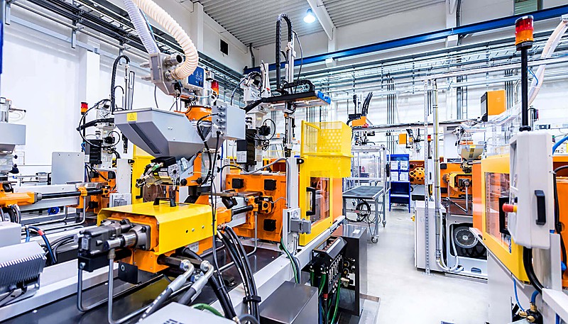
Spritzgießformen sind für die Herstellung von Hochpräzisionsteilen unerlässlich. Dabei wird geschmolzenes Material in einen Formhohlraum gespritzt. Diese Technologie kommt in vielen Branchen zum Einsatz und gewährleistet eine schnelle und gleichmäßige Produktion.
If you are comparing vendors or planning procurement, our injection molding supplier sourcing guide covers RFQ prep, qualification, and commercial risk checks.
Verfahren zum Spritzgießen injiziert unter hohem Druck geschmolzenes Material in eine Werkzeugkavität, wo es erstarrt und das gewünschte Produkt bildet. Die Werkzeugkonstruktion stellt sicher, dass das Produkt leicht entnommen werden kann und den erwarteten Abmessungen entspricht.

Die Materialien, die Struktur und der Aufbau von Spritzgusswerkzeugen stehen in direktem Zusammenhang mit der Qualität, Effizienz und den Kosten des Endprodukts.
Die Grundprinzipien der Konstruktion von Spritzgießwerkzeugen umfassen mehrere wichtige Schritte
Die Vorbereitung des geschmolzenen Kunststoffs ist die erste Phase. Das Kunststoffrohmaterial wird durch die Scherwirkung der Schnecke und des Heizgeräts geschmolzen.
Einspritzen: Das geschmolzene Plastik wird mit Hilfe des durch die Schnecke ausgeübten Drucks durch die Düse in den Formhohlraum gepresst.
Mit über 20 Jahren Erfahrung im Spritzgusswerkzeugbau betreibt ZetarMold in unserem Werk in Shanghai 47 Spritzgießmaschinen (90T–1850T) und bearbeitet Werkzeugkonstruktionen für Teile nahezu jeder Größe und Komplexität.
Nachdruck und Kühlung: Die Spritzgießmaschine hält diesen Druck für einige Zeit, um sicherzustellen, dass die Kavität gefüllt ist, und beginnt dann den Kühlprozess, wenn der Kunststoff beginnt, sich zu festigen.
Nachdem der Kunststoff ausgehärtet ist, öffnet sich die Form und das Ausstoßsystem – typischerweise Stifte, Platten oder Hülsen – drückt das fertige Teil aus der Kavität heraus. Ein geeignetes Ausstoßdesign sorgt dafür, dass das Teil sauber freigesetzt wird, ohne Verformung oder Beschädigung kritischer Oberflächen.
„Eine korrekte Werkzeugkonstruktion reduziert Fehler und verbessert die Produktionseffizienz.“Wahr
Gut konstruierte Spritzgusswerkzeuge ermöglichen eine gleichbleibende Teilequalität, geringere Ausschussraten und kürzere Zykluszeiten über die gesamte Produktion hinweg.
„Bei der Spritzgusswerkzeugkonstruktion geht es nur um die Produktform.“Falsch
Die Formkonstruktion umfasst auch Materialauswahl, Layout des Kühlsystems, Auswerfermechanismen und Prozessoptimierung für eine effiziente Produktion.
Was sind die Materialien für die Form?
Werkzeugmaterialien sind in Fertigungsprozessen wie dem Spritzgießen entscheidend, um Haltbarkeit, Präzision und Qualität zu gewährleisten. Die Materialwahl beeinflusst die Produktionseffizienz und die Eigenschaften des Endprodukts.
Die Wahl des Formenmaterials hat einen großen Einfluss auf die Lebensdauer der Form und die Qualität des Endprodukts. Gängige Formenwerkstoffe sind Stahl und Aluminium.
Stahl
Stahlformen bieten überlegene Härte, Verschleißfestigkeit und Wärmebehandlungseigenschaften mit einer deutlich längeren Arbeitslebensdauer als Aluminium – ideal für die Hochvolumenproduktion, wo Maßkonstanz kritisch ist.
Die Hauptnachteile von Stahlwerkzeugen sind längere Bearbeitungszeiten und höhere Materialkosten im Vergleich zu Aluminium. Stahl ist zudem deutlich schwerer, was die Handhabung erschwert und den Verschleiß an Wechselvorrichtungen erhöht. Bei hohen Stückzahlen gleicht die längere Werkzeuglebensdauer diese Nachteile jedoch meist aus.
Gängige Stähle:
P20-Stahl1 ist ein vielseitiger vorvergüteter Formenstahl (28–36 HRC), der weit verbreitet für Formgrundgestelle und große Kavitäten verwendet wird. Er bietet ausgezeichnete Bearbeitbarkeit und Polierbarkeit zu einem kostengünstigen Preis für Formen der mittleren Serienproduktion.
H13 ist ein Warmarbeitsstahl für Formen, die bei erhöhten Temperaturen betrieben werden. Er behält Härte und thermische Stabilität nach längerer Hitzeeinwirkung, mit einer typischen Härte von 44–52 HRC nach der Behandlung.
S136 ist ein rostfreier Werkzeugstahl mit ausgezeichneter Korrosionsbeständigkeit und Polierbarkeit. Er ist die bevorzugte Wahl für optische Linsen, transparente Teile und medizinische Formen, bei denen die Oberflächengüte von größter Bedeutung ist.
Aluminium
Aluminiumformen bieten erhebliche Gewichtsersparnis und etwa 4–5x bessere Wärmeleitfähigkeit als Stahl, was schnellere Kühlung und kürzere Zykluszeiten ermöglicht. Einfache Bearbeitbarkeit reduziert die Werkzeugvorlaufzeit und -kosten, was Aluminium ideal für Prototyping und Kleinserienproduktion macht.
Der Hauptnachteil ist geringere Härte und Verschleißfestigkeit, wodurch Aluminiumformen anfällig für Oberflächenschäden durch abrasive Harze sind. Am besten geeignet für Produktionsläufe unter 10.000–50.000 Teilen, wo die Werkzeuggeschwindigkeit wichtiger ist als die Langlebigkeit.
Gemeinsames Aluminium:
7075 ist eine der festesten Aluminiumlegierungen (Zugfestigkeit ~570 MPa). Dennoch bleibt seine Härte weit unter der von Werkzeugstahl, weshalb es sich am besten für Prototypenwerkzeuge und kleine Serien eignet.
Was umfasst die Gestaltung von Schimmelpilzstrukturen im Wesentlichen?
Die Gestaltung der Formstruktur ist der Schlüssel zur Herstellung hochwertiger Spritzgießformen, die Effizienz und Konsistenz während des Gießprozesses gewährleisten. Sie umfasst kritische Aspekte wie den Formfluss, die Kühlung und die Materialkompatibilität.
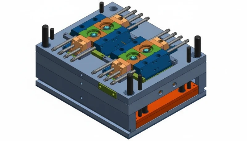
Die Werkzeugkonstruktion bezieht sich auf Kavität, Kern, Rahmen, Anguss, Führung und Auswerfsystem. Alle müssen sorgfältig ausgelegt sein, um Effizienz, Stabilität und einfache Wartung zu gewährleisten.
Hohlraum und Kern
Der Hohlraum bildet die Außenabmessungen des Produkts, während der Kern die Innenabmessungen liefert, die miteinander verbunden sind, um die endgültige und gewünschte Produktform und -größe zu erhalten.
Materialauswahl: Oft werden hochharte, verschleißfeste Stähle wie P20 oder H13 eingesetzt.
Design-Punkte: Die fertigen Oberflächen von Kavität und Kern sollten glatt sein, um eine hohe Maßhaltigkeit für die Oberflächengüte des Produkts zu gewährleisten.
Form Basis
Der Formsockel ist auch das Grundgerüst des Werkzeugs und hat die Aufgabe, alle Komponenten zu befestigen und miteinander zu verbinden. Er hat in der Regel eine Standardform, um den Zusammenbau von Formen und deren Austausch bei Bedarf zu ermöglichen.
Materialauswahl: Üblicherweise wird für das Formgrundgestell Stahl 45 oder Q235-Stahl verwendet, um die Stabilität des Grundgestells zu gewährleisten.
Bei ZetarMold produziert unsere interne Formenfertigungseinrichtung über 100 Formensätze pro Monat, wobei UG, SOLIDWORKS, MOLDFLOW und CAD verwendet werden, um den Formenfluss zu simulieren und Kühlungsdesigns zu validieren, bevor die Bearbeitung beginnt.
„Die Konstruktion der Formstruktur beeinflusst direkt die Teilequalität und die Produktionseffizienz.“Wahr
Ein geeignetes Kavitätenlayout, die Platzierung der Kühlkanäle und das Design des Ausstoßsystems bestimmen die Maßgenauigkeit, die Taktzeit und die Defektrate.
„Alle Formstrukturen sind unabhängig von der Anwendung gleich.“Falsch
Formstrukturen variieren erheblich je nach Teilgeometrie, Materialeigenschaften, Produktionsvolumen und branchenspezifischen Anforderungen.
Konstruktionspunkte: Das Formgrundgestell sollte ausreichende Robustheit und Stabilität besitzen, um mit dem Einspritzdruck, der Einspritztemperatur und dem allgemeinen Hin- und Herdruck während des Einspritzens zurechtzukommen.
Gating-System

Das Anschnittsystem besteht aus dem Hauptkanal, den Unterkanälen und den Anschnitten, durch die der geschmolzene Kunststoff in die Kavität geleitet wird. Ein effektives Anschnittsystem ist hilfreich, um die Qualität des Formteils zu erhöhen und die Menge des verwendeten Materials zu verringern.
Designpunkte: Der Hauptkanal sollte so kurz und so gerade wie möglich sein, um den Druckverlust zu minimieren und möglichst viel zu reduzieren.
Design-Punkte: Nebenkanäle sollten so angeordnet sein, dass sie eine gleichmäßige Masse auf die Kavität ausüben.
Design-Punkte: Die Art des Angusses sollte keinesfalls das Erscheinungsbild des Produkts beeinträchtigen oder seine Festigkeit mindern. Die Größe des verwendeten Angusses sollte angemessen sein.
Lenkungsmechanismus
Der Führungsmechanismus umfasst Führungsstifte und -buchsen, die bei der Ausrichtung zwischen den beweglichen und den festen Formen helfen.
Materialauswahl: Typisch wird hochharter Stahl verwendet, wie beispielsweise GCr15.
Konstruktionspunkte: Das Führungsmechanismus sollte in Bezug auf die Ausrichtung sehr präzise sein, um Fehlausrichtung über einen langen Zeitraum zu verhindern, und darüber hinaus sehr verschleißfest.
Auswurfmechanik
Der Auswerfer wird eingesetzt, um das geformte Produkt aus der Form zu nehmen, und normalerweise werden Auswerferstifte, Platten und Hülsen verwendet.
Design-Punkte: Eine weitere Anforderung an diese Kraft ist, dass sie konstant oder gleichmäßig sein sollte, da eine plötzliche Kraft das Produkt negativ beeinflussen kann. Die Bewegung des Auswerfersystems sollte ebenfalls gleichmäßig sein, um ein Haften zu vermeiden.
Was ist Flow Channel Design?
Das Fließkanaldesign umfasst die Auslegung von Anguss, Läufern und Angüssen, die das geschmolzene Plastik von der Maschinendüse in den Formhohlraum leiten.
Das Angussdesign beeinflusst die Produktqualität und Produktionseffizienz maßgeblich. Größe und Form des Angusses müssen auf Material und Bauteilgeometrie abgestimmt sein.
Hauptlaufbahn
Der Hauptkanal verbindet die Düse der Spritzgießmaschine mit den Unterkanälen und sollte so kurz und gerade wie möglich sein, um Druckverluste und Materialverluste zu reduzieren.
Designpunkte: Der Hauptkanaldurchmesser sollte richtig sein, um einen ausreichenden Fluss zu fördern und gleichzeitig den verschwenderischen Einsatz von Materialien zu reduzieren.
Sub-Runners
Die Unterkanäle verteilen die Kunststoffschmelze auf die einzelnen Kavitäten des Werkzeugs, wobei das Gleichgewicht eine wichtige Rolle spielt.
Design-Punkte: Die Querschnittsformen der Nebenkanäle sollten idealerweise kreisförmig oder halbkreisförmig sein, um den Strömungswiderstand zu verringern. Die Längen sollten möglichst gleich sein, damit die Füllzeit der Kavität für alle Längen nahezu identisch ist.
Pforten
Anschnitte sind das Mittel, mit dem die in die Kavität eingebrachte Kunststoffschmelze die Produktqualität beeinflusst.
Konstruktionspunkte: Die Angüsse sollten in Bereichen platziert werden, die das Erscheinungsbild oder die Festigkeit nicht beeinträchtigen. Ihre Größen müssen ausreichende Füllraten gewährleisten und gleichzeitig leicht zu entfernen sein. Verschiedene Angusstypen erfüllen unterschiedliche Produktanforderungen.
Darüber hinaus sollte das Design der Läufer berücksichtigt werden:
Angussausgleich: Bei Mehrfachkavitäten sicherstellen, dass die Angusslängen und deren Querschnittsfläche, da sie primär die Füllzeit der Formen bestimmen.
Angusskühlung: Ausreichende Vorkehrung für Kühlkanäle2 für den Angussbereich, sodass hohe Temperaturen den Schmelzfluss nicht beeinflussen.
Angusspräzision: Bearbeitungsgenauigkeit ist hoch und die Oberfläche glatt, um den Widerstand für Schmelzefluss und Druckabfall zu verringern.
Was ist ein Kühlsystemdesign?
Die Auslegung von Kühlsystemen ist entscheidend für die Optimierung von Fertigungsprozessen, die Gewährleistung einer gleichbleibenden Produktqualität und die Effizienz von Produktionszyklen.
„Die Fließkanalgestaltung beeinflusst die Formgebungseffizienz und die Bauteilqualität erheblich.“Wahr
Optimierte Anguss- und Einlassteilgeometrie reduziert Materialverschwendung, verkürzt die Zykluszeit und verbessert die Füllkonsistenz über alle Kavitäten hinweg.
„Das Strömungskanaldesign ist für alle Formtypen und Materialien identisch.“Falsch
Die Fließkanalgeometrie muss basierend auf Materialviskosität, Bauteildicke, Einlasstyp und Kavitätenanordnung für optimale Füllmuster angepasst werden.
Das Kühlsystem spielt bei der Konstruktion von Spritzgießwerkzeugen eine sehr wichtige Rolle, da es die Zykluszeit des Spritzgießens und die Werkzeugqualität reduziert. Zum Kühlsystem gehören vor allem die Kühlkanäle und die Kühlzeitstufen.
Kühlungskanäle
Kühlkanäle leiten Kühlwasser durch verschiedene Formteile, um überschüssige Wärme abzuführen.
Kühlkanäle sollten so nah wie möglich an der Kavitätenoberfläche positioniert werden, um die Wärmeableitung zu maximieren. Ein Abstand von Kanal zu Kavität von 1,5–2,5-fachen des Kanaldurchmessers sorgt für eine Balance zwischen Kühlleistung und struktureller Integrität des Stahlwerkzeugs.
Kühlmittelströmung sollte gleichmäßig über alle Kanäle verteilt werden, um lokale Hotspots zu vermeiden. Ungleichmäßige Kühlung führt zu differenzieller Schrumpfung, inneren Spannungen und Verzug im fertigen Teil. Strömungslenker oder Spiraleinsätze können helfen, den Fluss in unterversorgte Bereiche des Werkzeugs umzuleiten.
Der Kanaldurchmesser muss groß genug sein, um eine ausreichende Kühlmittelströmungsgeschwindigkeit – typischerweise 1,5–3 m/s – aufrechtzuerhalten, ohne einen übermäßigen Druckabfall zu erzeugen. Zu kleine Durchmesser bergen das Risiko von Verstopfungen durch Kalk oder Ablagerungen, während übermäßig große Kanäle die Strömungsturbulenz und Wärmeübertragungseffizienz reduzieren.
Abkühlungszeit
Die Abkühlzeit hängt auch von den Wandstärken des Produkts, dem verwendeten Materialtyp und den Temperaturen des Werkzeugs ab.
Ausreichende Abkühlzeit verhindert Verzug und Schrumpfung und gewährleistet Maßstabilität. Die optimale Dauer balanciert Bauteilintegrität und Durchsatz – typischerweise 60–80 % der gesamten Zykluszeit in den meisten Spritzgießprozessen.
Weitere Überlegungen zu Kühlsystemen sind:
Die Kühlmittelflussgeschwindigkeit erfordert eine sorgfältige Steuerung. Eine niedrige Geschwindigkeit kann die Kühleffizienz verringern, während eine hohe Geschwindigkeit zu Verstopfungen und Verschleiß der Form führen kann.
Kühlmitteltemperatur: Optimale Temperatur, da hohe Temperaturen die Abkühlrate verringern, während niedrige Temperaturen Kondensation auf der Formoberfläche verursachen und die Produktqualität beeinträchtigen können.
Kühlmittelqualität: Kühlmittel sauber halten, um Verstopfungen und Werkzeugschäden zu vermeiden.
Was ist ein Abgassystemdesign?
Die Entlüftungssystemgestaltung ist die Konstruktion von Entlüftungsnuten und -löchern, die eingeschlossene Luft und Gase während des Einspritzens aus der Werkzeugkavität entweichen lassen.
Das Entlüftungssystem leitet Gas aus dem Formhohlraum ab, um Defekte wie Blasen und Verbrennungen zu vermeiden, die sich direkt auf die Produktqualität und die Langlebigkeit der Form auswirken.
Entlüftungsrillen
Entlastung Nut3 ist ein Kanal für den Gastransport und befindet sich meist in der Trennlinie.
Konstruktionspunkte: Entlüftungsnuten dort anbringen, wo/wenn sich Gas frei ansammeln kann.
Designpunkte: Breite und Tiefe sollten den Querschnittsbereich für die erforderliche Entlüftung optimieren, sodass es auf der Seite des Kunststoffauswurfs keine Probleme gibt.
Designpunkte: Gleichmäßige Verteilung, um lokale Entlüftungsprobleme zu vermeiden.
Entlüftungslöcher
Die Entlüftungsöffnungen gehören zu den Komponenten des Entlüftungssystems, die sich normalerweise in dünnen Bereichen eines Produkts befinden.
Konstruktionspunkte: Angemessener Durchmesser, um die Entlüftung von Gasansammlungen nicht zu behindern und gleichzeitig einen ordnungsgemäßen Abzug zu gewährleisten.
Konstruktionspunkte: Die Positionierung sollte keinesfalls das Aussehen des Produkts oder dessen Festigkeit beeinflussen.
Entwurfspunkte: Menge und Position sollten im Einklang mit der Struktur der Form und der Form des Produkts angemessen sein.
Bei der Planung des Entlüftungssystems sollte auch berücksichtigt werden:
Systemwartung: Sie sollten regelmäßig gereinigt werden, um einen uneingeschränkten und ungehinderten Fluss zu gewährleisten, aber gelegentlich überprüft werden, um Werkzeuge vor Verstopfungen zu schützen, die Qualitätsprobleme verursachen können.
Systemkühlung: Bei Verwendung von Hochtemperaturformen Kühlmittel verwenden, um Kondensation der Gase während der Entlüftungsphase zu vermeiden.
Bearbeitungspräzision: Hohe Präzision mit glatten Oberflächen, um den Gasströmungswiderstand und Druckverlust zu reduzieren.
ZetarMold verarbeitet über 400 Kunststoffmaterialien. Unsere 8 Senior-Ingenieure überwachen die Werkzeugbearbeitungsqualität unter ISO 9001, ISO 13485, ISO 14001 und ISO 45001 zertifizierten Managementsystemen.
Was sind die Mold Processing?
Werkzeugbearbeitung ist die Reihe von CNC-Bearbeitung, EDM, Schleifen und Oberflächenbehandlungsschritten, die Rohstahl in ein Präzisionsspritzgießwerkzeug verwandeln.
„Ordentliche Werkzeugbearbeitung gewährleistet Maßgenauigkeit und Oberflächenqualität.“Wahr
CNC-Bearbeitung, EDM und Oberflächenbehandlung von Formenbauteilen schaffen präzise Toleranzen und glatte Oberflächen für eine konsistente Teileproduktion.
„Eine Werkzeugbearbeitung ist nur für Hochvolumen-Produktionswerkzeuge notwendig.“Falsch
Alle Formen benötigen unabhängig von der Stückzahl eine ordnungsgemäße Bearbeitung, Wärmebehandlung und Oberflächenveredelung, um die erforderlichen Toleranzen zu erreichen.
Die Formverarbeitung ist der Prozess der Umwandlung der Konstruktionszeichnung in die tatsächliche Form durch Grob- und Feinbearbeitung, Oberflächenbehandlung usw. Aus der Analyse geht hervor, dass die Genauigkeit und Qualität der Verarbeitung sich direkt auf die Funktion und Haltbarkeit der Form auswirken.
Grobzerspanung
Die Form wird aus dem Rohmaterial heraus grob bearbeitet, wobei üblicherweise CNC-Fräsen und Drehbänke verwendet werden.
Schlüsselpunkte: Ausreichend Bearbeitungszugabe vorsehen.
Schlüsselpunkte: Die optimale Geschwindigkeit und Vorschubrate, die helfen, Verformungen des Materials und graduellen Verschleiß von Werkzeugen und Maschinen zu vermeiden.
Schlüsselpunkte: Grobbearbeitung, um den Grat zu reduzieren und eine glattere Oberfläche zu erzielen.
Fertigstellung
Die Endbearbeitung erreicht die Form, um die Größe und die Spezifikationen der Form zu erreichen, und verwendet das Schleifverfahren, EDM und Polieren.
Schlüsselpunkte: Genauigkeit stellt sicher, dass Form und Größe für das Werkzeug korrekt sind.
Wichtige Punkte: Vermeiden Sie Überpolieren, um Maßabweichungen zu verhindern.
Schlüsselpunkte: Oberflächenbearbeitung mit der besten und geeignetsten Ausrüstung, um einen glatten und einwandfreien Finish zu erzielen.
Oberflächenbehandlung
Die Oberflächenbehandlung von Gussformen erhöht die Härte und die Verschleißfestigkeit der Gussformen, wobei die Verfahren Abschrecken, Nitrieren und die Verwendung einer Oberflächenbeschichtung zum Einsatz kommen.
Schlüsselpunkte: Wählen Sie geeignete Behandlungsmethoden basierend auf Werkzeugmaterial und Anwendung.
Wichtige Punkte: Um Formverformungen und Risse zu reduzieren, sollten die Behandlungsdauer und die Temperatur kontrolliert werden.
Schlüsselpunkte: Vor der Behandlung gründlich reinigen, um bessere Haftung und Leistung zu erzielen.
Wie pflegt man den Schimmel?
Eine ordnungsgemäße Werkzeugwartung ist entscheidend für eine gleichbleibende Qualität und Langlebigkeit beim Spritzgießen. Regelmäßige Pflege kann Ausfallzeiten und kostspielige Reparaturen verhindern.
Werkzeugwartung, sowohl täglich als auch periodisch, verlängert die Lebensdauer und senkt Produktionskosten durch konsequente Instandhaltung.
Routinemäßige Wartung
Schlüsselpunkte: Stellen Sie sicher, dass die Werkzeugoberfläche sauber ist, um zu verhindern, dass Temperaturen und Staub in das Werkzeug eindringen.
Wichtige Punkte: Schmieren Sie die Führungssäule und die Führungsbuchse regelmäßig, um die Flexibilität des Führungsmechanismus zu gewährleisten.
Wichtige Punkte: Es kann erforderlich sein, die anderen Komponenten der Form regelmäßig zu überprüfen und sie rechtzeitig zu reparieren oder auszutauschen.
Wichtige Punkte: Es ist notwendig zu bestätigen, ob der Kühlkanal und das Abgassystem normal geöffnet sind und ob sie blockiert sind. Wenn sie blockiert sind, sollten sie umgehend freigemacht werden.
Regelmäßige Wartung
Unter Wartung versteht man die allgemeine Überprüfung und Reparatur der Form, nachdem sie einige Zeit benutzt wurde.
Wichtige Punkte: Überprüfen Sie den Formhohlraum und den Kern und suchen Sie nach dem Teil des Hohlraums, der stark abgenutzt ist, und reparieren oder ersetzen Sie ihn.
Key Points: Check whether the guiding mechanism, demoulding mechanism and other parts of the mold are normal, and make necessary adjustments or replacements.
Key Points: Check whether the cooling system of the mold and the exhaust system of the mold are normal and perform the need for cleaning and clearing.
Key Points: Thoroughly clean and lubricate the mold to ensure that the mold is in good working condition.
Was sind die häufigsten Probleme bei der Formgestaltung und ihre Lösungen?
Common mold design problems include poor cooling, uneven material flow, and improper gate placement that affect part quality.
“Regular cleaning extends mold lifespan and maintains part quality.”Wahr
Scheduled maintenance including cleaning, lubrication, and inspection prevents wear, corrosion, and dimensional drift over production cycles.
“Mold maintenance is unnecessary if the mold is properly designed.”Falsch
All molds require regular cleaning and inspection regardless of design quality to maintain dimensional accuracy and prevent progressive wear.
Several common issues can affect part quality and production rate if not properly addressed during mold design.
Sinkende Markierungen
Problem Description: The surface of the product is dented, which affects the appearance.
Solution: It is advised to the position as well as the size of the gate to be such that it can accommodate melt and fill up the cavity uniformly.
Solution: Maximize the cooling circuit design and layout in order to allow equal distribution of the cooling to the products.
Solution: Adjust the holding time and pressure to reduce melt shrinkage.
Blitzlicht
Problem Description: Scrap forms on the peripheral region of the product giving it a poor appearance and may not be of accurate dimension.
Solution: About the parting surface design of the mold, try to make the mold closed to the minimum.
Solution: Enhance the clamping force of the mold to prevent the mold from separating during the injection molding manufacturing process.
Solution: To check the mold, first it is required to check the guiding mechanism of the mold and the clamping mechanism of the mold.
Blase
Problem Description: There are visible pores on the body of the product or in the product itself in the form of bubbles which influences the looks and the durability.
Solution: Minimize the design of the exhaust system so as to allow the gas in the mold cavity to be released effectively.
Solution: Adjust the parameters used in injection like the speed of injection, injection force and temperature of injection molding materials in a bid to minimize generation of gases.
Solution: Check the drying of raw materials to ensure that the moisture content of raw materials is at an appropriate level.
Verformung und Verwerfung
Problem Description: The injection molded part becomes partly shrunken or distorted after cooling and the dimensional stability and surface finish of the product are compromised.
Solution: Improve on the cooling system so as to give as equal temperatures to all the injection molded parts.
Solution: Adjust the holding time and holding pressureset in the injection parameters to reduce internal stress.
Solution: Strengthen the changes in mold structure design, such as adding reinforcing ribs to make the product have uniform wall thickness and consistent wall thickness.

Instabilität der Dimensionen
Problem Description: The geometry is out of the required sizes and standards to affect the assembly and usage of the product.
Solution: Examine the correctness of machining on the mold and assembly realization of products to verify whether or not the sizes of the mold conform with the injection molding design specifications.
Solution: Control the process parameters as injection pressure, holding pressure time and cooling time should be controlled in order to have stable size of the product.
Solution: Confirm the manufacture stability of the injection molding machines in order to have ability to determine the variation of the injection molding.
Häufig gestellte Fragen
What is the most important factor in injection mold design?
The most critical factor in injection mold design is achieving uniform wall thickness throughout the part. Uneven walls cause differential cooling, which directly leads to sink marks, warpage, and dimensional inconsistency in the finished product. In our experience at ZetarMold working with over 400 materials, parts with wall thickness variations exceeding 15 percent almost always require costly mold rework to achieve acceptable quality. Beyond wall thickness, proper gate placement and an efficient cooling system layout are equally important for determining cycle time and long-term mold durability.
How long does it take to design an injection mold?
A typical injection mold design takes 2 to 4 weeks depending on part complexity. Simple single-cavity molds for straightforward geometries may take as little as 5 to 7 days from concept to completed drawings. Complex multi-cavity molds with side actions, lifters, or unscrewing mechanisms can require 4 to 6 weeks of engineering time. The design phase includes 3D CAD modeling, mold flow simulation to validate fill patterns, and multiple design review iterations. At ZetarMold, our 8 senior engineers follow a structured review process that catches issues early.
What software is used for injection mold design?
The industry standard software for injection mold design includes SOLIDWORKS and UG also known as NX for 3D CAD modeling, and Autodesk Moldflow for flow simulation and thermal analysis. These tools allow engineers to visualize cavity layout, simulate plastic fill patterns, and optimize cooling channel placement before any steel is cut. At ZetarMold, our design team uses SOLIDWORKS, MOLDFLOW, and CAD in combination to validate gate placement, predict weld line positions, and analyze cooling efficiency, reducing first-article defects by up to 60 percent compared to traditional trial-and-error methods.
Was sind die typischen Kosten für ein Spritzgusswerkzeug?
Injection mold costs range widely depending on complexity and production requirements. Simple single-cavity aluminum prototype molds start around 1,000 to 3,000 dollars, while production-grade steel molds with multiple cavities and hot runner systems typically cost between 10,000 and 50,000 dollars. Highly complex molds with side actions, unscrewing cores, or specialized surface finishes can exceed 100,000 dollars. Key cost drivers include the number of cavities, mold material choice, expected production volume, required surface finish quality, and tolerance specifications for the application.
How do you prevent flash in injection mold design?
Flash prevention starts with precision parting surface design and proper clamping force calculation. The mold parting line must be machined to flatness tolerances within 0.01 millimeters to ensure complete closure under injection pressure. Vent grooves should be sized correctly at 0.01 to 0.03 millimeters depth to allow trapped gas to escape without permitting molten material to seep through. The injection molding machine must have sufficient tonnage. At ZetarMold, our 47 presses range from 90T to 1850T, allowing precise matching of machine capacity to each mold.
What is the difference between a cold runner and a hot runner mold?
A cold runner mold channels molten plastic through unheated passages, resulting in solidified runner waste that must be separated, reground, and recycled or discarded. A hot runner mold uses electrically heated manifold systems to keep plastic in a molten state within the distribution channels, eliminating runner waste entirely and reducing cycle time. Hot runner molds cost 20 to 40 percent more upfront due to the heated manifold and temperature controllers, but they save 15 to 30 percent on material costs for high-volume production runs and improve consistency.
What tolerance can injection molding achieve?
Standard injection molding achieves tolerances of plus or minus 0.1 millimeters for dimensions under 25 millimeters. Precision molding with optimized process control, tight temperature regulation, and high-quality tooling can achieve plus or minus 0.05 millimeters or tighter for critical features. Tolerance capability depends heavily on material shrinkage characteristics, with semi-crystalline materials exhibiting higher variability than amorphous ones. For tight-tolerance applications, ZetarMold engineers use Moldflow simulation during the design phase to predict and compensate for shrinkage before the mold is built.
Warum ist das Spritzgießformen-Design für den Herstellungserfolg entscheidend?
Injection mold design is the most important factor for part quality, production efficiency, and cost control in plastic manufacturing.
Dieser Artikel bietet praktische Referenzen für Spritzguss-Formenkonstrukteure. Für Unterstützung bei der individuellen Formkonstruktion kontaktieren Sie ZetarMold für fachkundige Unterstützung.
Erfahren Sie mehr über Spritzgießen: Ein umfassender Leitfaden: Spritzgießen ist ein Fertigungsverfahren, bei dem geschmolzener Kunststoff in eine Form gespritzt wird, um Teile mit hoher Genauigkeit und Wiederholbarkeit herzustellen. ↩
Erfahren Sie mehr über Was ist Kern und Kavität beim Spritzgießen? Die Kavität und der Kern in einer typischen Kunststoff-Spritzgießmaschine einer Spritzgussform sind die formgebenden Teile der Form. ↩
Erfahren Sie mehr über Arten von Angüssen beim Spritzgießen: Ein umfassender Designleitfaden: Ein Spritzgieß-Anguss ist eine konstruierte Öffnung, meist klein, die den Fluss von geschmolzenem Kunststoff in den Formhohlraum steuert. ↩
Erfahren Sie über H13 Werkzeugstahl: H13 ist ein Warmarbeitswerkzeugstahl, der eine gute Resistenz gegen thermische Ermüdung, Erosion und Verschleiß hat und weitgehend für die Herstellung von Formen und Werkzeugen verwendet wird. ↩
Erfahren Sie über vier wichtige Prinzipien, die bei der Design der Wandstärke berücksichtigt werden sollten: Die Wandstärke von Kunststoffprodukten ist eine kritische strukturelle Eigenschaft, die häufig bei der Design von Kunststoffproduktstrukturen diskutiert und berücksichtigt wird. ↩
Erfahren Sie über Wie man den Haltedruck und die Haltezeit beim Spritzgießen bestimmt? Der Einspritzdruck umfasst sowohl Druck als auch Geschwindigkeit. ↩
Get competitive pricing, DFM feedback, and production timeline from ZetarMold’s engineering team.
Request a Free Quote →
-
P20-Stahl: P20 Stahl bezeichnet ASTM A681, das legierte Werkzeugstähle einschließlich P20 mit typischer Härte von 28-36 HRC für Grundplattenanwendungen spezifiziert ↩
-
Kühlkanäle: Kühlkanäle können laut Forschung im Polymeringenieurwesen bis zu 70 % der gesamten Spritzgießzykluszeit ausmachen ↩
-
Nut: Nut bezieht sich auf Standard-Entlüftungsnut-Tiefen von 0,01 bis 0,03 mm für die meisten Thermoplaste, um Gasentweichung ohne Gratbildung zu ermöglichen ↩


