 Przejdź do treści

Tolerancje linii podziału są unikalne. linia podziału1 nie jest wadą; jest to nieunikniona cecha formowanie wtryskowe process. But where you put it, and how you design around it, can make the difference between a production-ready part and a costly redesign.
W naszym warsztacie form widzieliśmy, jak inżynierowie mylili się z linią podziału więcej razy, niż możemy zliczyć. Wydaje się to proste — wystarczy podzielić formę na pół — dopóki nie zdamy sobie sprawy, że linia podziału dokładnie określa, gdzie błysk2 pojawia się, które wymiary są utrzymywane w ścisłej tolerancji, czy część w ogóle może być prawidłowo wyprężona z formy i ile będzie kosztować narzędzie. Ten przewodnik obejmuje wszystko, co inżynierowie muszą wiedzieć o powierzchniach rozdzielających i liniach podziału, aby można było zrobić to dobrze za pierwszym razem.
- The parting line is the physical trace left where two mold halves meet during injection.
- Parting surface design directly impacts part quality, mold cost, and production efficiency.
- Five main types: flat, stepped, angled, curved, and composite parting surfaces.
- DFM analysis before tooling can prevent 80% of parting-line-related production issues.
- Flash at the parting line is controlled by mold precision, clamping force, and material selection.

What Is a Parting Surface in Injection Molding?
Powierzchnia rozdzielająca to płaski lub profilowany interfejs, gdzie dwie połówki formy spotykają się i uszczelniają podczas wtryskiwania. Jeśli porównujesz dostawców lub planujesz zakupy, nasz injection molding supplier sourcing guide covers RFQ prep, qualification, and commercial risk checks.
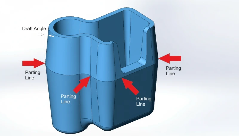
A parting surface is the contact interface between two mold halves — the cavity side (A-side) and the core side (B-side). When the mold closes, these two surfaces press together under tons of clamping force. The parting line is the narrow trace this interface leaves on the finished plastic part.
In a narrow sense, the parting surface refers specifically to the main separation plane at the largest contour of the part — the surface that divides cavity from core. In a broader sense, it includes all contact surfaces between mold modules: slider faces, lifter interfaces, insert joints, and ejector pin seats. Every one of these interfaces can leave a visible line on the part.
Industry professionals often call it the “PL surface” or “PL line” for short. The thickness and visibility of this line depend on mold precision, clamping force, material viscosity, and processing conditions. A well-designed parting surface with tight mold tolerances produces a line so fine it’s barely visible — typically 0.01 to 0.05 mm wide. A poorly designed one produces visible flash, mismatch, or step marks that require secondary trimming operations.
How Is the Parting Line Formed During Molding?
Linia podziału powstaje, gdy dwie połówki formy zamykają się pod siłą docisku, tworząc fizyczną spoinę na gotowej części. An forma wtryskowa consists of at least two halves — a fixed half mounted to the stationary platen and a moving half mounted to the moving platen. When the molding machine closes the mold, the two halves meet at the parting surface.
During injection, molten plastic fills the cavity under high pressure (typically 500–2,000 bar). Some of this pressure acts directly on the parting surface. Even with precision-ground mold faces, a microscopic gap exists between the halves. If the injection pressure exceeds what the clamping force can contain, material forces its way into this gap — that’s flash.
After cooling and solidification, the mold opens along the parting plane. The part stays on the core side (thanks to shrinkage gripping the core), and the ejector system pushes it free. The seam where the two mold halves met is now permanently recorded on the part surface as the parting line.

In most cases, the parting line runs perpendicular to the mold opening direction. But for complex geometries — parts with undercuts, side features, or asymmetrical profiles — the parting surface may include stepped, angled, or curved sections. These multi-directional parting surfaces require additional mold mechanisms like sliders, lifters, or angled pins to function correctly.
“A parting line width of 0.01 mm is considered acceptable for most cosmetic parts.”Prawda
For visible/cosmetic surfaces, parting lines under 0.05 mm are generally acceptable. High-precision molds can achieve 0.01 mm or less, which is nearly invisible to the naked eye.
“The parting line is a defect caused by poor mold manufacturing.”Fałsz
The parting line is an unavoidable feature of any two-part mold. It exists on every injection molded part regardless of mold quality. What varies is the line’s visibility — a precision mold produces a barely perceptible line, while a worn or poorly designed mold produces visible flash.
What Are the Types of Parting Surfaces?
Pięć rodzajów powierzchni rozdzielających to płaskie, schodkowe, skośne, zakrzywione i kompozytowe. Wybór odpowiedniego typu jest jedną z pierwszych i najważniejszych decyzji w projektowaniu formy. Oto pięć głównych kategorii:
Flat (Straight) Parting Surface
The simplest and most common type. The parting surface is a single flat plane perpendicular to the mold opening direction. This works well for cup-shaped parts, flat panels, and any geometry where the largest cross-section is a clean horizontal plane. Flat parting surfaces are the easiest to machine, seal, and maintain — which translates directly to lower mold cost and more consistent part quality.
Stepped Parting Surface
When a part has features at different heights that cannot be accommodated by a single flat plane, the parting surface steps up or down to follow the part contour. Stepped parting surfaces create lateral forces during injection that the mold must resist — typically using interlocking features or wedge-shaped inserts. If the step height is excessive, designers add cushion pads to partially flatten the surface while maintaining necessary clearance.
Angled (Inclined) Parting Surface
For parts with angled features or asymmetrical profiles, the parting surface follows an inclined plane. The angled surface includes a sealing section along the slope (to contain the plastic) and a flat reference section (for machining, alignment, and measurement). This type requires careful attention to lateral force management — the injection pressure creates a sideways thrust that must be balanced.
Curved (Contoured) Parting Surface
Complex consumer products — think power tool housings, automotive interior trim, or medical device enclosures — often need parting surfaces that follow curved part contours. The mold face is CNC-machined to match the 3D profile. Curved parting surfaces demand high machining precision and careful sealing surface design to prevent flash along the entire contour.
Composite (Combined) Parting Surface
Many real-world parts combine two or more of the above types. A single mold might have a flat section in one area, a step in another, and a curved section elsewhere. Composite parting surfaces require extra attention at the transition zones — sharp corners at the junction between different surface types must be smoothed to avoid weak mold steel and to prevent flash.
What Are the Key Parting Surface Design Principles?
Good parting surface design is governed by a set of practical principles that balance part quality, mold cost, and production reliability. In our 20+ years of mold making, these are the rules that separate a smooth production run from weeks of mold modifications.
Principle 1: Ensure Proper Demolding
The main parting surface should be located at the largest cross-section of the part in the mold opening direction. This is the fundamental rule. Placing the parting line anywhere else means you’ll need side actions (sliders, lifters) to release the part — adding cost, complexity, and maintenance points to the mold. Every additional side action is another potential source of flash, wear, and downtime.
Principle 2: Keep the Part on the Correct Side
Since the ejection system is on the moving mold half (B-side), the parting surface should be designed so the part stays on the core after the mold opens. If the part sticks to the cavity (A-side), you’ll need a dedicated ejection mechanism on the fixed half — adding cost and complexity. Draft angles on the core side and undercut features help ensure reliable part retention.
Principle 3: Preserve Dimensional Accuracy
Any dimension that crosses the parting line is subject to variation from mold alignment, clamping deflection, and flash formation. For critical dimensions — especially those requiring tight coaxiality or positional tolerance — place all related features on the same side of the mold. A stepped hole that requires ±0.02 mm coaxiality should be formed by a single core on one mold half, not split across both.
Jak cienką może być wykonana linia podziału?
Trapped air in the cavity causes burns, short shots, and weak weld lines. The parting surface should be positioned so that the melt front reaches the parting line last — allowing air to escape through the natural gap between mold halves. If the parting surface seals before the cavity is full, air gets trapped in dead-end regions with no escape path.
Principle 5: Simplify Mold Construction
Every additional complexity in the parting surface adds machining time, inspection cost, and maintenance risk. If the part geometry allows it, a flat parting surface is always preferable. When complexity is unavoidable — like stepped or curved surfaces — try to combine multiple features into shared surfaces to reduce the total number of parting transitions.
“Dimensions that cross the parting line have more variation than dimensions on one mold half.”Prawda
Any dimension spanning both mold halves is affected by mold alignment accuracy, clamping force consistency, thermal expansion differences, and flash thickness. Holding tight tolerances (±0.05 mm or better) across the parting line is significantly harder than on a single mold half.
“A stepped parting surface always requires side-core pulling mechanisms.”Fałsz
Stepped parting surfaces follow height changes in the part geometry but still open in the main mold direction. Side-core pulling (sliders) is needed for undercuts — features that are perpendicular to the mold opening direction. A step can exist without any undercut.
How Does Parting Line Placement Affect Part Quality?
The parting line location is arguably the single most impactful decision in mold design. It directly affects four quality dimensions: appearance, dimensional accuracy, surface finish, and tooling longevity.
Appearance: On cosmetic surfaces, the parting line is a visible seam. For consumer products, this means the parting line must be hidden in a non-visible area, disguised along a feature edge, or finished to near-invisibility. If your part has a visible Class A surface, the parting line needs to be on the back or along a natural break line. We’ve worked with automotive clients who rejected entire production batches because the parting line shifted 0.2 mm from the agreed position.
Dimensional accuracy: As discussed above, cross-parting-line dimensions inherit the alignment tolerance of the mold. For parts with ±0.1 mm general tolerances, this is usually manageable. For precision components with ±0.02 mm requirements, you need to avoid splitting critical features across the parting line entirely.
Wykończenie powierzchni: The parting line area typically has a different surface texture than the rest of the part. Even with polished molds, the junction where the two halves meet creates a slight step or witness line. If the part requires a specific SPI finish (like SPI A-2 for lens-quality surfaces), the parting line area will never match the surrounding finish perfectly.
Tooling longevity: Parting surfaces bear the full brunt of clamping force cycle after cycle. A well-designed parting surface with proper support and sufficient bearing area will last hundreds of thousands of shots. A poorly designed one — with sharp edges, insufficient sealing area, or excessive overhang — will wear, dinge, and develop flash within tens of thousands of cycles.
When Should You Use Stepped or Curved Parting Surfaces?
Schodkowe powierzchnie rozdzielające stosuje się, gdy część ma elementy na różnych wysokościach, a zakrzywione powierzchnie są potrzebne dla geometrii niepłaskiej. Oto, kiedy używać każdego typu i jakie kompromisy akceptować.
Use a stepped parting surface when: The part has features at significantly different heights that cannot be demolded with a single flat plane. Electronics housings with connector cutouts at different heights, enclosure halves with stepped mounting bosses, and pump components with multiple sealing levels are typical candidates. The key engineering concern with stepped surfaces is managing lateral injection forces — the melt pressure pushes sideways on the step, and without proper interlocks or wedge supports, the mold halves can shift, causing dimensional drift and flash.
Use a curved parting surface when: The part has organic, non-planar geometry — think consumer product housings, automotive trim, or ergonomic grips. The parting surface follows the 3D contour of the part to hide the line along a natural edge or feature boundary. This approach produces the best cosmetic results but demands high-precision CNC machining and careful mold texturing to ensure the surface finish is consistent across the curved interface.
Trade-off analysis: Going from flat to stepped to curved parting surfaces, each step roughly adds 15–30% to mold construction cost. Stepped surfaces require additional interlock machining and potentially larger mold bases. Curved surfaces demand 5-axis CNC work and extended fitting time. The production penalty is real too — complex parting surfaces wear faster, need more frequent maintenance, and are more sensitive to process parameter drift.
“Curved parting surfaces are always more expensive to manufacture than flat ones.”Prawda
Curved parting surfaces require 5-axis CNC machining, extended fitting/spotting time, and more complex inspection. A flat parting surface can be surface-ground to tolerance quickly, while a curved one must be machined and hand-fitted along the entire contour. The cost premium is typically 20–40% over a comparable flat design.
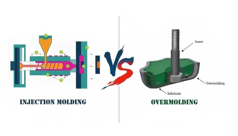
“You can eliminate the parting line entirely by using insert molding.”Fałsz
Insert molding still uses a two-part mold and therefore still produces a parting line. The insert is placed in the mold before injection, but the mold still opens and closes along a parting surface. The only way to avoid a parting line is to use a process without a split mold, such as machining from solid stock.
How Can DFM Analysis Optimize Your Parting Line?
Design for Manufacturing (DFM3) analiza jest najlepszym narzędziem do prawidłowego określenia linii podziału przed jakimkolwiek cięciem stali. W naszym fabrycznym procesie DFM mapujemy decyzję dotyczącą podziału względem etapów wtryskiwania, tak aby linia podziału wspierała napełnianie, dociskanie, chłodzenie, wyprężanie i kontrolę. Dokładny przegląd DFM ocenia geometrię części, identyfikuje optymalne położenie linii podziału, wskazuje potencjalne problemy z odformowaniem i szacuje wymaganą złożoność formy.
W ZetarMold nasi 8 starszych inżynierów wnosi do każdego przeglądu DFM ponad 10-letnie doświadczenie w projektowaniu form. W naszych próbach narzędziowych nasi inżynierowie procesowi porównują również nadlewy na linii podziału z jednorodnością stopu z wtryskarki ślimakowej, ponieważ niestabilny front stopu może sprawić, że marginalna powierzchnia rozdzielająca wygląda gorzej niż w rzeczywistości. Oto, co obejmuje prawidłowa analiza DFM linii podziału:
1. Undercut identification: Every undercut feature is catalogued. For each one, we determine whether it needs a slider, lifter, collapsible core, or can be resolved by simply relocating the parting line. In many cases, a slight redesign of the undercut feature eliminates the need for a side action entirely — saving significant tooling cost.
2. Draft angle verification: All surfaces perpendicular to the parting line need adequate draft — typically 1–3° depending on material and surface finish. Zero-draft or negative-draft walls near the parting line will cause sticking, scoring, or ejection failures.
3. Flash risk assessment: We evaluate which areas of the parting surface will see the highest melt pressure and whether the mold has sufficient bearing area to contain it. Thin-wall sections near the parting line are high-risk zones for flash.
W naszej fabryce w Szanghaju obsługujemy 47 maszyn do wtryskiwania tworzyw o zakresie od 90T do 1850T, wspieranych przez wewnętrzny zakład produkcji form. Każde narzędzie, które budujemy, przechodzi rygorystyczną weryfikację linii rozdzielającej — ponieważ nawet 0,05 mm niedopasowania może spowodować widoczny wypływ na gotowej części.
“Nylon (PA) requires tighter parting line tolerances than polycarbonate (PC) due to its lower melt viscosity.”Prawda
Nylon has a much lower melt viscosity than polycarbonate, meaning it flows more easily into microscopic gaps at the parting surface. This makes nylon parts more prone to flash, requiring tighter mold fits (typically 0.02 mm or less) compared to polycarbonate (0.05 mm or less).
“A DFM analysis is only necessary for complex or high-volume parts.”Fałsz
DFM analysis is valuable for every injection molded part, regardless of complexity or volume. Even simple parts can have parting line issues that are cheap to fix in the design stage but expensive to correct after the mold is built. A 30-minute DFM review can save thousands in mold modifications.
Często zadawane pytania
What causes visible flash along the parting line?
Flash forms when molten plastic escapes through the gap between mold halves at the parting surface during the injection phase. Common causes include insufficient clamping force relative to injection pressure, worn or damaged mold faces that no longer seal tightly, poor mold alignment causing uneven bearing pressure, excessive packing pressure held too long, and low-viscosity materials like nylon that flow easily into small gaps. Regular mold maintenance — including re-spotting parting surfaces every 50,000–100,000 shots — combined with proper process parameter control and adequate machine tonnage are the primary defenses against flash at the parting line.
Can a parting line be completely eliminated from an injection molded part?
No, it cannot. Every injection molded part produced with a conventional two-part mold will always have a parting line where the cavity and core halves meet. The goal is not elimination but minimization — through precision mold construction with ground parting surfaces, strategic parting line placement on non-cosmetic surfaces, and optimized processing parameters. For applications where any visible seam is unacceptable, alternative manufacturing processes like CNC machining from solid stock or additive manufacturing can produce seamless parts, though at significantly higher per-part cost and lower production throughput.
How thin can a parting line be made?
Przewodnik po powierzchniach i liniach rozdzielających form wtryskowych | ZetarMold
What is the difference between a parting surface and a parting line?
The parting surface is the entire mating interface between the two mold halves — it is a 2D or 3D surface within the mold tool itself. The parting line is the narrow 1D trace that this interface leaves on the surface of the molded plastic part after ejection. In other words, the parting surface is a mold design feature that exists in the tool steel, while the parting line is the visible evidence of that surface transferred to the finished part. A single parting surface can produce a complex, winding parting line if the mold geometry includes stepped, angled, or curved sections.
Does parting line location affect injection molding cost?
Yes, significantly. A simple flat parting surface is the most economical to tool, machine, and maintain. Each increase in complexity — stepping the surface, adding curves, or introducing additional parting interfaces — adds machining time, fitting labor, inspection requirements, and long-term maintenance cost. Moving from a flat to a composite parting surface typically increases mold cost by 30–50%. Parting lines that require side actions such as sliders, lifters, or angled pins add even more cost, as each side action requires its own guide system, wear plate, and return mechanism, plus additional fitting and testing during mold commissioning.
What draft angle is needed near the parting line?
A minimum of 1° draft per side is recommended for all surfaces perpendicular to the parting line in standard production molding. For parts with textured surfaces (such as MT, VDI, or spark-eroded finishes), 1.5–3° per side is required — deeper textures need more draft to prevent the texture from scuffing during ejection. Polished or mirror-finish surfaces may get by with as little as 0.5° draft. Zero-draft or negative-draft walls near the parting line risk part sticking, surface scoring during ejection, increased ejector pin marks, and cycle-to-cycle dimensional variation. Draft should be specified during part design, not discovered as a problem during mold tryout.
How does clamping force relate to parting line quality?
The molding machine’s clamping force must exceed the total separating force generated by injection pressure acting on the projected area of the parting surface. If clamping force is insufficient, the mold opens slightly during the injection and packing phases, creating a gap that allows plastic to escape as flash along the parting line. The required clamping force is calculated as: injection pressure × projected cavity area × safety factor (typically 1.1–1.2). Running a mold on an undersized machine is the single most common cause of flash at the parting line in production environments. Selecting the right machine tonnage during production planning is essential for consistent parting line quality.
Nasz zespół inżynieryjny w ZetarMold wnosi do każdego projektu ponad 20-letnie doświadczenie w projektowaniu form, 8 starszych inżynierów oraz wewnętrzny zakład produkcji form. Od analizy DFM przez produkcję optymalizujemy twoją linię rozdzielającą pod kątem jakości, kosztów i wydajności. Dzięki 47 maszynom do wtryskiwania tworzyw (90T-1850T) i ponad 400 materiałom plastikowym obsługujemy wszystko, od precyzyjnych komponentów optycznych po duże części konstrukcyjne.
Request a Free Quote →
-
linia podziału: linia podziału odnosi się do widocznej linii na odlanej części, gdzie dwie połówki formy spotykają się podczas procesu wtryskiwania. ↩
-
błysk: nadlewy oznaczają nadmiar materiału, który wydostaje się z wnęki formy na linii podziału podczas wtryskiwania, tworząc cienkie, niepożądane krawędzie. ↩
-
DFM: DFM oznacza projektowanie pod kątem wytwarzania — praktykę projektowania części tak, aby były łatwiejsze i bardziej opłacalne w produkcji. ↩


