 Zum Inhalt springen

Jede zusätzliche Komplexität in der Trennungsebene erhöht die Bearbeitungszeit, die Prüfkosten und das Wartungsrisiko. Wenn die Geometrie des Bauteils es ermöglicht, ist eine flache Trennungsebene immer vorzuziehen. Wenn Komplexität unvermeidbar ist – beispielsweise bei abgestuften oder gekrümmten Oberflächen – versuchen Sie, mehrere Merkmale in gemeinsamen Oberflächen zu kombinieren, um die Gesamtzahl der Trennungsebenenübergänge zu reduzieren. Trennungslinie1 ist kein Fehler; es ist ein unvermeidbares Merkmal der Spritzgießen process. But where you put it, and how you design around it, can make the difference between a production-ready part and a costly redesign.
In unserer Formenwerkstatt haben wir gesehen, dass Ingenieure die Trennlinie öfter falsch gesetzt haben, als wir zählen können. Es scheint einfach zu sein – einfach die Form in zwei Hälften teilen – bis man erkennt, dass die Trennlinie genau bestimmt, wo Blitzlicht2 erscheint, welche Maße mit enger Toleranz gehalten werden, ob das Teil überhaupt ordnungsgemäß aus der Form ausgeworfen werden kann und wie viel die Werkzeugkosten sein werden. Dieser Leitfaden behandelt alles, was Ingenieure über Trennflächen und Trennlinien wissen müssen, damit Sie es gleich beim ersten Mal richtig machen.
- The parting line is the physical trace left where two mold halves meet during injection.
- Parting surface design directly impacts part quality, mold cost, and production efficiency.
- Five main types: flat, stepped, angled, curved, and composite parting surfaces.
- DFM analysis before tooling can prevent 80% of parting-line-related production issues.
- Flash at the parting line is controlled by mold precision, clamping force, and material selection.

What Is a Parting Surface in Injection Molding?
Eine Trennfläche ist die flache oder konturierte Schnittstelle, an der sich zwei Formhälften während des Spritzgießens treffen und abdichten. Wenn Sie Anbieter vergleichen oder die Beschaffung planen, unsere injection molding supplier sourcing guide covers RFQ prep, qualification, and commercial risk checks.
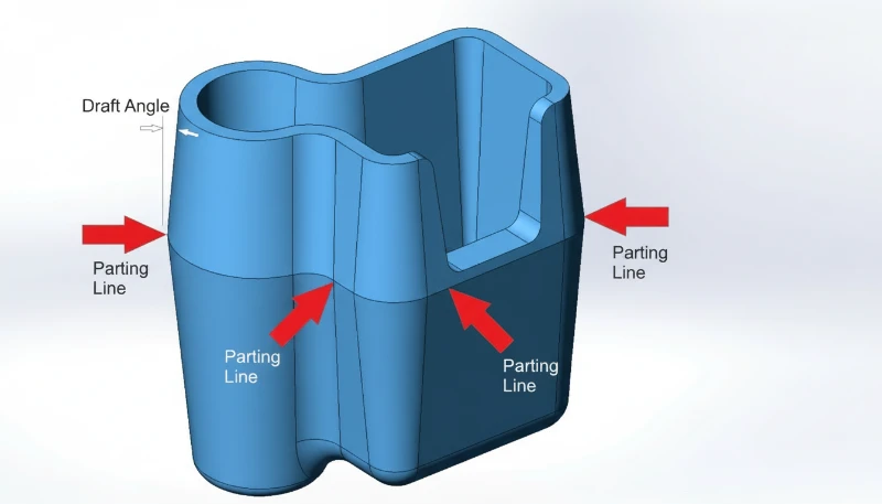
A parting surface is the contact interface between two mold halves — the cavity side (A-side) and the core side (B-side). When the mold closes, these two surfaces press together under tons of clamping force. The parting line is the narrow trace this interface leaves on the finished plastic part.
In a narrow sense, the parting surface refers specifically to the main separation plane at the largest contour of the part — the surface that divides cavity from core. In a broader sense, it includes all contact surfaces between mold modules: slider faces, lifter interfaces, insert joints, and ejector pin seats. Every one of these interfaces can leave a visible line on the part.
Fachleute der Branche nennen es oft kurz „PL-Fläche“ oder „PL-Linie“. Die Dicke und Sichtbarkeit dieser Linie hängen von der Formpräzision, der Schließkraft, der Materialviskosität und den Verarbeitungsbedingungen ab. Eine gut gestaltete Trennfläche mit engen Formtoleranzen erzeugt eine so feine Linie, dass sie kaum sichtbar ist – typischerweise 0,01 bis 0,05 mm breit. Eine schlecht gestaltete erzeugt sichtbaren Grat, Fehlausrichtung oder Stufenmarkierungen, die sekundäre Nachbearbeitungsoperationen erfordern.
How Is the Parting Line Formed During Molding?
Die Trennlinie entsteht, wenn sich zwei Formhälften unter Schließkraft schließen und eine physische Naht am fertigen Teil erzeugen. Ein Spritzgussform consists of at least two halves — a fixed half mounted to the stationary platen and a moving half mounted to the moving platen. When the molding machine closes the mold, the two halves meet at the parting surface.
Während des Einspritzens füllt geschmolzener Kunststoff unter hohem Druck (typischerweise 500–2.000 bar) die Kavität. Ein Teil dieses Drucks wirkt direkt auf die Trennfläche. Selbst mit präzisionsgeschliffenen Formflächen existiert ein mikroskopischer Spalt zwischen den Hälften. Wenn der Einspritzdruck das übersteigt, was die Schließkraft enthalten kann, drängt Material in diesen Spalt – das ist Grat.
After cooling and solidification, the mold opens along the parting plane. The part stays on the core side (thanks to shrinkage gripping the core), and the ejector system pushes it free. The seam where the two mold halves met is now permanently recorded on the part surface as the parting line.

In most cases, the parting line runs perpendicular to the mold opening direction. But for complex geometries — parts with undercuts, side features, or asymmetrical profiles — the parting surface may include stepped, angled, or curved sections. These multi-directional parting surfaces require additional mold mechanisms like sliders, lifters, or angled pins to function correctly.
„Eine Trennlinienbreite von 0,01 mm wird für die meisten kosmetischen Teile als akzeptabel angesehen.“Wahr
For visible/cosmetic surfaces, parting lines under 0.05 mm are generally acceptable. High-precision molds can achieve 0.01 mm or less, which is nearly invisible to the naked eye.
„Die Trennlinie ist ein Fehler, der durch schlechte Formherstellung verursacht wird.“Falsch
Die Trennlinie ist ein unvermeidliches Merkmal jeder zweiteiligen Form. Sie existiert auf jedem spritzgegossenen Teil, unabhängig von der Formqualität. Was variiert, ist die Sichtbarkeit der Linie – eine Präzisionsform erzeugt eine kaum wahrnehmbare Linie, während eine abgenutzte oder schlecht konstruierte Form sichtbaren Grat erzeugt.
What Are the Types of Parting Surfaces?
Die fünf Arten von Trennflächen sind flach, gestuft, abgewinkelt, gekrümmt und zusammengesetzt. Die Wahl des richtigen Typs ist eine der ersten und wichtigsten Entscheidungen im Formendesign. Hier sind die fünf Hauptkategorien:
Flat (Straight) Parting Surface
The simplest and most common type. The parting surface is a single flat plane perpendicular to the mold opening direction. This works well for cup-shaped parts, flat panels, and any geometry where the largest cross-section is a clean horizontal plane. Flat parting surfaces are the easiest to machine, seal, and maintain — which translates directly to lower mold cost and more consistent part quality.
Stepped Parting Surface
When a part has features at different heights that cannot be accommodated by a single flat plane, the parting surface steps up or down to follow the part contour. Stepped parting surfaces create lateral forces during injection that the mold must resist — typically using interlocking features or wedge-shaped inserts. If the step height is excessive, designers add cushion pads to partially flatten the surface while maintaining necessary clearance.
Angled (Inclined) Parting Surface
For parts with angled features or asymmetrical profiles, the parting surface follows an inclined plane. The angled surface includes a sealing section along the slope (to contain the plastic) and a flat reference section (for machining, alignment, and measurement). This type requires careful attention to lateral force management — the injection pressure creates a sideways thrust that must be balanced.
Curved (Contoured) Parting Surface
Complex consumer products — think power tool housings, automotive interior trim, or medical device enclosures — often need parting surfaces that follow curved part contours. The mold face is CNC-machined to match the 3D profile. Curved parting surfaces demand high machining precision and careful sealing surface design to prevent flash along the entire contour.
Composite (Combined) Parting Surface
Many real-world parts combine two or more of the above types. A single mold might have a flat section in one area, a step in another, and a curved section elsewhere. Composite parting surfaces require extra attention at the transition zones — sharp corners at the junction between different surface types must be smoothed to avoid weak mold steel and to prevent flash.
What Are the Key Parting Surface Design Principles?
Good parting surface design is governed by a set of practical principles that balance part quality, mold cost, and production reliability. In our 20+ years of mold making, these are the rules that separate a smooth production run from weeks of mold modifications.
Principle 1: Ensure Proper Demolding
Die Haupttrennfläche sollte sich am größten Querschnitt des Teils in der Richtung der Formöffnung befinden. Dies ist die grundlegende Regel. Wenn die Trennlinie an einer anderen Stelle platziert wird, benötigen Sie Seitenaktionen (Schieber, Auswerfer), um das Teil freizugeben – was Kosten, Komplexität und Wartungspunkte an der Form erhöht. Jede zusätzliche Seitenaktion ist eine weitere potenzielle Quelle für Grat, Verschleiß und Ausfallzeiten.
Principle 2: Keep the Part on the Correct Side
Da sich das Auswerfsystem auf der beweglichen Formhälfte (B-Seite) befindet, sollte die Trennfläche so gestaltet sein, dass das Teil nach dem Öffnen der Form am Kern bleibt. Wenn das Teil an der Kavität (A-Seite) haftet, benötigen Sie einen speziellen Auswerfmechanismus auf der festen Hälfte – was Kosten und Komplexität erhöht. Schrägungswinkel auf der Kernseite und Hinterschneidungen helfen, eine zuverlässige Teilerhaltung zu gewährleisten.
Principle 3: Preserve Dimensional Accuracy
Any dimension that crosses the parting line is subject to variation from mold alignment, clamping deflection, and flash formation. For critical dimensions — especially those requiring tight coaxiality or positional tolerance — place all related features on the same side of the mold. A stepped hole that requires ±0.02 mm coaxiality should be formed by a single core on one mold half, not split across both.
Principle 4: Optimize Venting
Trapped air in the cavity causes burns, short shots, and weak weld lines. The parting surface should be positioned so that the melt front reaches the parting line last — allowing air to escape through the natural gap between mold halves. If the parting surface seals before the cavity is full, air gets trapped in dead-end regions with no escape path.
Principle 5: Simplify Mold Construction
Every additional complexity in the parting surface adds machining time, inspection cost, and maintenance risk. If the part geometry allows it, a flat parting surface is always preferable. When complexity is unavoidable — like stepped or curved surfaces — try to combine multiple features into shared surfaces to reduce the total number of parting transitions.
„Abmessungen, die die Trennlinie kreuzen, weisen mehr Variation auf als Abmessungen auf einer Formhälfte.“Wahr
Any dimension spanning both mold halves is affected by mold alignment accuracy, clamping force consistency, thermal expansion differences, and flash thickness. Holding tight tolerances (±0.05 mm or better) across the parting line is significantly harder than on a single mold half.
„Eine abgestufte Trennfläche erfordert immer Seitenkern-Zugmechanismen.“Falsch
Stepped parting surfaces follow height changes in the part geometry but still open in the main mold direction. Side-core pulling (sliders) is needed for undercuts — features that are perpendicular to the mold opening direction. A step can exist without any undercut.
How Does Parting Line Placement Affect Part Quality?
The parting line location is arguably the single most impactful decision in mold design. It directly affects four quality dimensions: appearance, dimensional accuracy, surface finish, and tooling longevity.
Appearance: Auf kosmetischen Oberflächen ist die Trennlinie eine sichtbare Naht. Für Konsumgüter bedeutet dies, dass die Trennlinie in einem nicht sichtbaren Bereich versteckt, entlang einer Merkmalskante getarnt oder bis zur fast unsichtbaren Fertigung bearbeitet werden muss. Wenn Ihr Teil eine sichtbare Klasse-A-Oberfläche hat, muss die Trennlinie auf der Rückseite oder entlang einer natürlichen Bruchlinie liegen. Wir haben mit Automobilkunden gearbeitet, die ganze Produktionschargen ablehnten, weil sich die Trennlinie um 0,2 mm von der vereinbarten Position verschoben hatte.
Dimensional accuracy: As discussed above, cross-parting-line dimensions inherit the alignment tolerance of the mold. For parts with ±0.1 mm general tolerances, this is usually manageable. For precision components with ±0.02 mm requirements, you need to avoid splitting critical features across the parting line entirely.
Oberflächenbehandlung: The parting line area typically has a different surface texture than the rest of the part. Even with polished molds, the junction where the two halves meet creates a slight step or witness line. If the part requires a specific SPI finish (like SPI A-2 for lens-quality surfaces), the parting line area will never match the surrounding finish perfectly.
Tooling longevity: Parting surfaces bear the full brunt of clamping force cycle after cycle. A well-designed parting surface with proper support and sufficient bearing area will last hundreds of thousands of shots. A poorly designed one — with sharp edges, insufficient sealing area, or excessive overhang — will wear, dinge, and develop flash within tens of thousands of cycles.
When Should You Use Stepped or Curved Parting Surfaces?
Gestufte Trennflächen werden verwendet, wenn ein Teil Merkmale in verschiedenen Höhen aufweist, und gekrümmte Flächen sind für nicht-planare Geometrien erforderlich. Hier ist, wann jeder Typ verwendet werden sollte und welche Kompromisse Sie eingehen.
Use a stepped parting surface when: The part has features at significantly different heights that cannot be demolded with a single flat plane. Electronics housings with connector cutouts at different heights, enclosure halves with stepped mounting bosses, and pump components with multiple sealing levels are typical candidates. The key engineering concern with stepped surfaces is managing lateral injection forces — the melt pressure pushes sideways on the step, and without proper interlocks or wedge supports, the mold halves can shift, causing dimensional drift and flash.
Use a curved parting surface when: The part has organic, non-planar geometry — think consumer product housings, automotive trim, or ergonomic grips. The parting surface follows the 3D contour of the part to hide the line along a natural edge or feature boundary. This approach produces the best cosmetic results but demands high-precision CNC machining and careful mold texturing to ensure the surface finish is consistent across the curved interface.
Trade-off analysis: Going from flat to stepped to curved parting surfaces, each step roughly adds 15–30% to mold construction cost. Stepped surfaces require additional interlock machining and potentially larger mold bases. Curved surfaces demand 5-axis CNC work and extended fitting time. The production penalty is real too — complex parting surfaces wear faster, need more frequent maintenance, and are more sensitive to process parameter drift.
„Gekrümmte Trennflächen sind immer teurer in der Herstellung als flache.“Wahr
Curved parting surfaces require 5-axis CNC machining, extended fitting/spotting time, and more complex inspection. A flat parting surface can be surface-ground to tolerance quickly, while a curved one must be machined and hand-fitted along the entire contour. The cost premium is typically 20–40% over a comparable flat design.
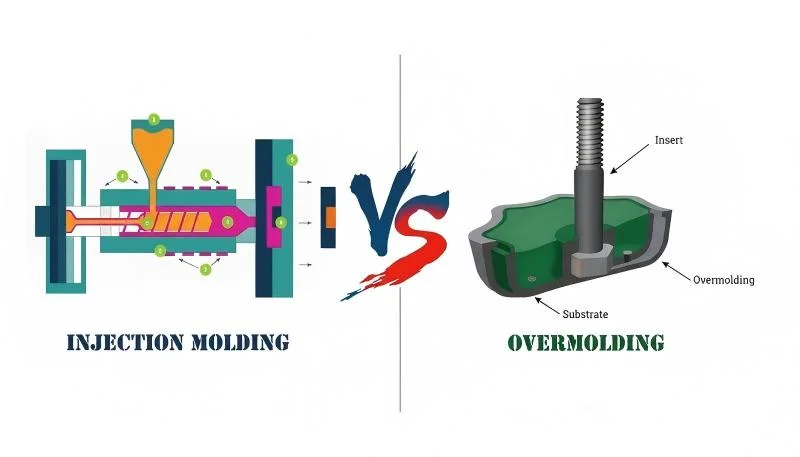
„Sie können die Trennlinie vollständig eliminieren, indem Sie Einspritzgießen verwenden.“Falsch
Insert molding still uses a two-part mold and therefore still produces a parting line. The insert is placed in the mold before injection, but the mold still opens and closes along a parting surface. The only way to avoid a parting line is to use a process without a split mold, such as machining from solid stock.
How Can DFM Analysis Optimize Your Parting Line?
Design for Manufacturing (DFM3) Analyse ist Ihr bestes Werkzeug, um die Trennlinie richtig zu setzen, bevor Stahl geschnitten wird. In unserem Fabrik-DFM-Workflow ordnen wir die Trennlinienentscheidung den Schritten des Spritzgießens zu, sodass die Trennlinie das Füllen, Nachdrücken, Kühlen, Auswerfen und die Inspektion unterstützt. Eine gründliche DFM-Prüfung bewertet die Teilgeometrie, identifiziert den optimalen Trennlinienort, markiert potenzielle Entformungsprobleme und schätzt die erforderliche Formkomplexität ab.
Bei ZetarMold bringt jeder unserer 8 leitenden Ingenieure mehr als 10 Jahre Erfahrung im Formendesign in jede DFM-Prüfung ein. In unseren Werkzeugversuchen vergleichen unsere Prozessingenieure auch den Trennlinien-Grat mit der Schmelzkonsistenz der Schneckenspritzgießmaschine, da eine instabile Schmelzfront eine marginale Trennfläche schlechter aussehen lassen kann, als sie tatsächlich ist. Hier ist, was eine ordnungsgemäße Trennlinien-DFM-Analyse umfasst:
1. Undercut identification: Every undercut feature is catalogued. For each one, we determine whether it needs a slider, lifter, collapsible core, or can be resolved by simply relocating the parting line. In many cases, a slight redesign of the undercut feature eliminates the need for a side action entirely — saving significant tooling cost.
2. Draft angle verification: All surfaces perpendicular to the parting line need adequate draft — typically 1–3° depending on material and surface finish. Zero-draft or negative-draft walls near the parting line will cause sticking, scoring, or ejection failures.
3. Flash risk assessment: We evaluate which areas of the parting surface will see the highest melt pressure and whether the mold has sufficient bearing area to contain it. Thin-wall sections near the parting line are high-risk zones for flash.
In unserer Fabrik in Shanghai betreiben wir 47 Spritzgießmaschinen mit einer Leistung von 90T bis 1850T, unterstützt durch eine eigene Formenbauanlage. Jedes Werkzeug, das wir bauen, durchläuft eine strenge Überprüfung der Trennlinie – denn bereits eine Abweichung von 0,05 mm kann sichtbare Gratbildung am fertigen Teil verursachen.
„Nylon (PA) erfordert aufgrund seiner niedrigeren Schmelzviskosität engere Toleranzen an der Trennlinie als Polycarbonat (PC).“Wahr
Nylon has a much lower melt viscosity than polycarbonate, meaning it flows more easily into microscopic gaps at the parting surface. This makes nylon parts more prone to flash, requiring tighter mold fits (typically 0.02 mm or less) compared to polycarbonate (0.05 mm or less).
„Eine DFM-Analyse ist nur für komplexe oder hochvolumige Teile notwendig.“Falsch
DFM analysis is valuable for every injection molded part, regardless of complexity or volume. Even simple parts can have parting line issues that are cheap to fix in the design stage but expensive to correct after the mold is built. A 30-minute DFM review can save thousands in mold modifications.
Häufig gestellte Fragen
What causes visible flash along the parting line?
Flash forms when molten plastic escapes through the gap between mold halves at the parting surface during the injection phase. Common causes include insufficient clamping force relative to injection pressure, worn or damaged mold faces that no longer seal tightly, poor mold alignment causing uneven bearing pressure, excessive packing pressure held too long, and low-viscosity materials like nylon that flow easily into small gaps. Regular mold maintenance — including re-spotting parting surfaces every 50,000–100,000 shots — combined with proper process parameter control and adequate machine tonnage are the primary defenses against flash at the parting line.
Can a parting line be completely eliminated from an injection molded part?
No, it cannot. Every injection molded part produced with a conventional two-part mold will always have a parting line where the cavity and core halves meet. The goal is not elimination but minimization — through precision mold construction with ground parting surfaces, strategic parting line placement on non-cosmetic surfaces, and optimized processing parameters. For applications where any visible seam is unacceptable, alternative manufacturing processes like CNC machining from solid stock or additive manufacturing can produce seamless parts, though at significantly higher per-part cost and lower production throughput.
How thin can a parting line be made?
With a precision-ground mold using hardened tool steel (HRC 48–52), parting lines can be reduced to 0.005–0.01 mm width — virtually invisible to the naked eye and undetectable by touch. Standard production molds typically produce lines of 0.02–0.05 mm, which are visible but acceptable for most non-cosmetic applications. The achievable thinness depends on several factors: mold machining accuracy (surface grinding vs. milling), steel hardness and wear resistance, clamping force adequacy, injection pressure profile, and the melt viscosity of the molding material. Higher-precision molds cost more but deliver consistently finer parting lines over longer production runs.
DFM steht für Design for Manufacturing – die Praxis, Teile so zu gestalten, dass sie einfacher und kostengünstiger herzustellen sind.
The parting surface is the entire mating interface between the two mold halves — it is a 2D or 3D surface within the mold tool itself. The parting line is the narrow 1D trace that this interface leaves on the surface of the molded plastic part after ejection. In other words, the parting surface is a mold design feature that exists in the tool steel, while the parting line is the visible evidence of that surface transferred to the finished part. A single parting surface can produce a complex, winding parting line if the mold geometry includes stepped, angled, or curved sections.
Does parting line location affect injection molding cost?
Yes, significantly. A simple flat parting surface is the most economical to tool, machine, and maintain. Each increase in complexity — stepping the surface, adding curves, or introducing additional parting interfaces — adds machining time, fitting labor, inspection requirements, and long-term maintenance cost. Moving from a flat to a composite parting surface typically increases mold cost by 30–50%. Parting lines that require side actions such as sliders, lifters, or angled pins add even more cost, as each side action requires its own guide system, wear plate, and return mechanism, plus additional fitting and testing during mold commissioning.
What draft angle is needed near the parting line?
A minimum of 1° draft per side is recommended for all surfaces perpendicular to the parting line in standard production molding. For parts with textured surfaces (such as MT, VDI, or spark-eroded finishes), 1.5–3° per side is required — deeper textures need more draft to prevent the texture from scuffing during ejection. Polished or mirror-finish surfaces may get by with as little as 0.5° draft. Zero-draft or negative-draft walls near the parting line risk part sticking, surface scoring during ejection, increased ejector pin marks, and cycle-to-cycle dimensional variation. Draft should be specified during part design, not discovered as a problem during mold tryout.
How does clamping force relate to parting line quality?
Die Schließkraft der Spritzgießmaschine muss die gesamte Trennkraft überschreiten, die durch den Einspritzdruck auf die projizierte Fläche der Trennfläche erzeugt wird. Wenn die Schließkraft unzureichend ist, öffnet sich die Form während der Einspritz- und Nachdruckphasen leicht, wodurch ein Spalt entsteht, der es dem Kunststoff ermöglicht, als Grat entlang der Trennlinie zu entweichen. Die erforderliche Schließkraft wird berechnet als: Einspritzdruck × projizierte Kavitätenfläche × Sicherheitsfaktor (typischerweise 1,1–1,2). Das Betreiben einer Form auf einer zu kleinen Maschine ist die häufigste Ursache für Grat an der Trennlinie in Produktionsumgebungen. Die Auswahl der richtigen Maschinentonnage während der Produktionsplanung ist für eine gleichbleibende Qualität der Trennlinie unerlässlich.
Unser Ingenieurteam bei ZetarMold bringt über 20 Jahre Formenbau-Erfahrung, 8 leitende Ingenieure und eine eigene Formenbauanlage in jedes Projekt ein. Von der DFM-Analyse bis zur Produktion optimieren wir Ihre Trennlinie für Qualität, Kosten und Leistung. Mit 47 Spritzgießmaschinen (90T-1850T) und über 400 Kunststoffmaterialien bewältigen wir alles von präzisen optischen Komponenten bis hin zu großen Strukturteilen.
Request a Free Quote →
-
Trennungslinie: Trennlinie bezieht sich auf die sichtbare Linie an einem geformten Teil, an der sich die beiden Hälften der Form während des Spritzgießprozesses treffen. ↩
-
Blitzlicht: Grat bezieht sich auf überschüssiges Material, das während des Spritzgießens an der Trennlinie aus dem Formhohlraum entweicht und dünne, unerwünschte Kanten bildet. ↩
-
DFM: DFM steht für Design for Manufacturing – die Praxis, Teile so zu gestalten, dass sie einfacher und kostengünstiger herzustellen sind. ↩


