 콘텐츠로 건너뛰기

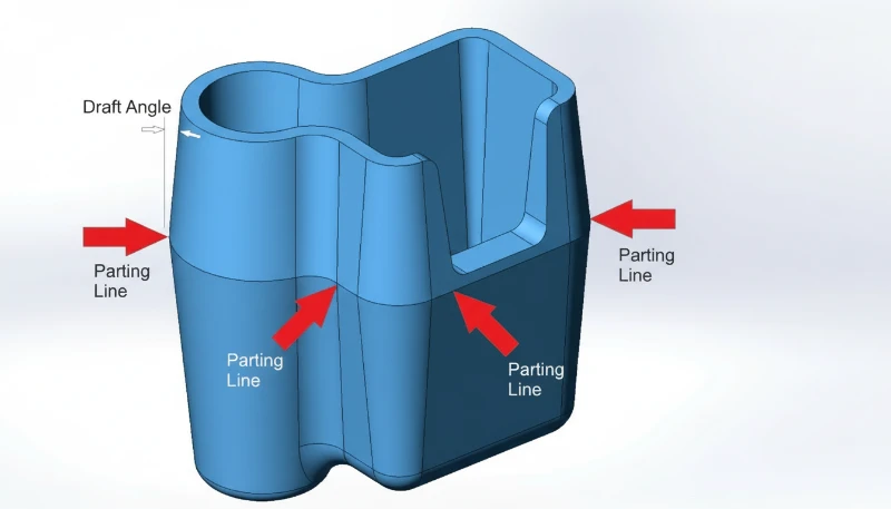
Every injection molded part has one — that thin line running along the surface where the mold halves meet. The 이별 라인1 is not a defect; it is an unavoidable feature of the 사출 성형 process. But where you put it, and how you design around it, can make the difference between a production-ready part and a costly redesign.
In our mold shop, we have seen engineers get the parting line wrong more times than we can count. It seems simple — just split the mold in half — until you realize that the parting line determines exactly where 플래시2 appears, which dimensions are held to a tight tolerance, whether the part can even be properly ejected from the mold, and how much the tooling will cost. This guide covers everything engineers need to know about parting surfaces and parting lines so you can get it right the first time.
- The parting line is the physical trace left where two mold halves meet during injection.
- Parting surface design directly impacts part quality, mold cost, and production efficiency.
- Five main types: flat, stepped, angled, curved, and composite parting surfaces.
- DFM analysis before tooling can prevent 80% of parting-line-related production issues.
- Flash at the parting line is controlled by mold precision, clamping force, and material selection.

What Is a Parting Surface in Injection Molding?
A parting surface is the flat or contoured interface where two mold halves meet and seal during injection. If you are comparing vendors or planning procurement, our injection molding supplier sourcing guide covers RFQ prep, qualification, and commercial risk checks.
A parting surface is the contact interface between two mold halves — the cavity side (A-side) and the core side (B-side). When the mold closes, these two surfaces press together under tons of clamping force. The parting line is the narrow trace this interface leaves on the finished plastic part.
In a narrow sense, the parting surface refers specifically to the main separation plane at the largest contour of the part — the surface that divides cavity from core. In a broader sense, it includes all contact surfaces between mold modules: slider faces, lifter interfaces, insert joints, and ejector pin seats. Every one of these interfaces can leave a visible line on the part.
Industry professionals often call it the “PL surface” or “PL line” for short. The thickness and visibility of this line depend on mold precision, clamping force, material viscosity, and processing conditions. A well-designed parting surface with tight mold tolerances produces a line so fine it’s barely visible — typically 0.01 to 0.05 mm wide. A poorly designed one produces visible flash, mismatch, or step marks that require secondary trimming operations.
How Is the Parting Line Formed During Molding?
The parting line is formed when two mold halves close together under clamping force, creating a physical seam on the finished part. An 사출 금형 consists of at least two halves — a fixed half mounted to the stationary platen and a moving half mounted to the moving platen. When the molding machine closes the mold, the two halves meet at the parting surface.
During injection, molten plastic fills the cavity under high pressure (typically 500–2,000 bar). Some of this pressure acts directly on the parting surface. Even with precision-ground mold faces, a microscopic gap exists between the halves. If the injection pressure exceeds what the clamping force can contain, material forces its way into this gap — that’s flash.
After cooling and solidification, the mold opens along the parting plane. The part stays on the core side (thanks to shrinkage gripping the core), and the ejector system pushes it free. The seam where the two mold halves met is now permanently recorded on the part surface as the parting line.

In most cases, the parting line runs perpendicular to the mold opening direction. But for complex geometries — parts with undercuts, side features, or asymmetrical profiles — the parting surface may include stepped, angled, or curved sections. These multi-directional parting surfaces require additional mold mechanisms like sliders, lifters, or angled pins to function correctly.
“A parting line width of 0.01 mm is considered acceptable for most cosmetic parts.”True
For visible/cosmetic surfaces, parting lines under 0.05 mm are generally acceptable. High-precision molds can achieve 0.01 mm or less, which is nearly invisible to the naked eye.
“The parting line is a defect caused by poor mold manufacturing.”False
The parting line is an unavoidable feature of any two-part mold. It exists on every injection molded part regardless of mold quality. What varies is the line’s visibility — a precision mold produces a barely perceptible line, while a worn or poorly designed mold produces visible flash.
What Are the Types of Parting Surfaces?
The five types of parting surfaces are flat, stepped, angled, curved, and composite. Choosing the right type is one of the first and most important decisions in mold design. Here are the five main categories:
Flat (Straight) Parting Surface
The simplest and most common type. The parting surface is a single flat plane perpendicular to the mold opening direction. This works well for cup-shaped parts, flat panels, and any geometry where the largest cross-section is a clean horizontal plane. Flat parting surfaces are the easiest to machine, seal, and maintain — which translates directly to lower mold cost and more consistent part quality.
Stepped Parting Surface
When a part has features at different heights that cannot be accommodated by a single flat plane, the parting surface steps up or down to follow the part contour. Stepped parting surfaces create lateral forces during injection that the mold must resist — typically using interlocking features or wedge-shaped inserts. If the step height is excessive, designers add cushion pads to partially flatten the surface while maintaining necessary clearance.
Angled (Inclined) Parting Surface
For parts with angled features or asymmetrical profiles, the parting surface follows an inclined plane. The angled surface includes a sealing section along the slope (to contain the plastic) and a flat reference section (for machining, alignment, and measurement). This type requires careful attention to lateral force management — the injection pressure creates a sideways thrust that must be balanced.
Curved (Contoured) Parting Surface
Complex consumer products — think power tool housings, automotive interior trim, or medical device enclosures — often need parting surfaces that follow curved part contours. The mold face is CNC-machined to match the 3D profile. Curved parting surfaces demand high machining precision and careful sealing surface design to prevent flash along the entire contour.
Composite (Combined) Parting Surface
Many real-world parts combine two or more of the above types. A single mold might have a flat section in one area, a step in another, and a curved section elsewhere. Composite parting surfaces require extra attention at the transition zones — sharp corners at the junction between different surface types must be smoothed to avoid weak mold steel and to prevent flash.
What Are the Key Parting Surface Design Principles?
Good parting surface design is governed by a set of practical principles that balance part quality, mold cost, and production reliability. In our 20+ years of mold making, these are the rules that separate a smooth production run from weeks of mold modifications.
Principle 1: Ensure Proper Demolding
The main parting surface should be located at the largest cross-section of the part in the mold opening direction. This is the fundamental rule. Placing the parting line anywhere else means you’ll need side actions (sliders, lifters) to release the part — adding cost, complexity, and maintenance points to the mold. Every additional side action is another potential source of flash, wear, and downtime.
Principle 2: Keep the Part on the Correct Side
Since the ejection system is on the moving mold half (B-side), the parting surface should be designed so the part stays on the core after the mold opens. If the part sticks to the cavity (A-side), you’ll need a dedicated ejection mechanism on the fixed half — adding cost and complexity. Draft angles on the core side and undercut features help ensure reliable part retention.
Principle 3: Preserve Dimensional Accuracy
Any dimension that crosses the parting line is subject to variation from mold alignment, clamping deflection, and flash formation. For critical dimensions — especially those requiring tight coaxiality or positional tolerance — place all related features on the same side of the mold. A stepped hole that requires ±0.02 mm coaxiality should be formed by a single core on one mold half, not split across both.
Principle 4: Optimize Venting
Trapped air in the cavity causes burns, short shots, and weak weld lines. The parting surface should be positioned so that the melt front reaches the parting line last — allowing air to escape through the natural gap between mold halves. If the parting surface seals before the cavity is full, air gets trapped in dead-end regions with no escape path.
Principle 5: Simplify Mold Construction
Every additional complexity in the parting surface adds machining time, inspection cost, and maintenance risk. If the part geometry allows it, a flat parting surface is always preferable. When complexity is unavoidable — like stepped or curved surfaces — try to combine multiple features into shared surfaces to reduce the total number of parting transitions.
“Dimensions that cross the parting line have more variation than dimensions on one mold half.”True
Any dimension spanning both mold halves is affected by mold alignment accuracy, clamping force consistency, thermal expansion differences, and flash thickness. Holding tight tolerances (±0.05 mm or better) across the parting line is significantly harder than on a single mold half.
“A stepped parting surface always requires side-core pulling mechanisms.”False
Stepped parting surfaces follow height changes in the part geometry but still open in the main mold direction. Side-core pulling (sliders) is needed for undercuts — features that are perpendicular to the mold opening direction. A step can exist without any undercut.
How Does Parting Line Placement Affect Part Quality?
The parting line location is arguably the single most impactful decision in mold design. It directly affects four quality dimensions: appearance, dimensional accuracy, surface finish, and tooling longevity.
외관: On cosmetic surfaces, the parting line is a visible seam. For consumer products, this means the parting line must be hidden in a non-visible area, disguised along a feature edge, or finished to near-invisibility. If your part has a visible Class A surface, the parting line needs to be on the back or along a natural break line. We’ve worked with automotive clients who rejected entire production batches because the parting line shifted 0.2 mm from the agreed position.
Dimensional accuracy: As discussed above, cross-parting-line dimensions inherit the alignment tolerance of the mold. For parts with ±0.1 mm general tolerances, this is usually manageable. For precision components with ±0.02 mm requirements, you need to avoid splitting critical features across the parting line entirely.
표면 마감: The parting line area typically has a different surface texture than the rest of the part. Even with polished molds, the junction where the two halves meet creates a slight step or witness line. If the part requires a specific SPI finish (like SPI A-2 for lens-quality surfaces), the parting line area will never match the surrounding finish perfectly.
Tooling longevity: Parting surfaces bear the full brunt of clamping force cycle after cycle. A well-designed parting surface with proper support and sufficient bearing area will last hundreds of thousands of shots. A poorly designed one — with sharp edges, insufficient sealing area, or excessive overhang — will wear, dinge, and develop flash within tens of thousands of cycles.
When Should You Use Stepped or Curved Parting Surfaces?
Stepped parting surfaces are used when a part has features at different heights, and curved surfaces are needed for non-planar geometry. Here is when to use each type and what trade-offs you accept.
Use a stepped parting surface when: The part has features at significantly different heights that cannot be demolded with a single flat plane. Electronics housings with connector cutouts at different heights, enclosure halves with stepped mounting bosses, and pump components with multiple sealing levels are typical candidates. The key engineering concern with stepped surfaces is managing lateral injection forces — the melt pressure pushes sideways on the step, and without proper interlocks or wedge supports, the mold halves can shift, causing dimensional drift and flash.
Use a curved parting surface when: The part has organic, non-planar geometry — think consumer product housings, automotive trim, or ergonomic grips. The parting surface follows the 3D contour of the part to hide the line along a natural edge or feature boundary. This approach produces the best cosmetic results but demands high-precision CNC machining and careful mold texturing to ensure the surface finish is consistent across the curved interface.
Trade-off analysis: Going from flat to stepped to curved parting surfaces, each step roughly adds 15–30% to mold construction cost. Stepped surfaces require additional interlock machining and potentially larger mold bases. Curved surfaces demand 5-axis CNC work and extended fitting time. The production penalty is real too — complex parting surfaces wear faster, need more frequent maintenance, and are more sensitive to process parameter drift.
“Curved parting surfaces are always more expensive to manufacture than flat ones.”True
Curved parting surfaces require 5-axis CNC machining, extended fitting/spotting time, and more complex inspection. A flat parting surface can be surface-ground to tolerance quickly, while a curved one must be machined and hand-fitted along the entire contour. The cost premium is typically 20–40% over a comparable flat design.
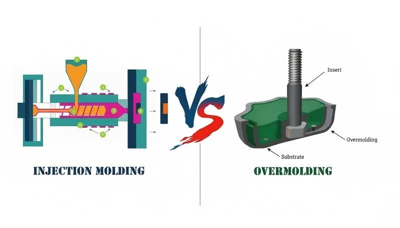
“You can eliminate the parting line entirely by using insert molding.”False
Insert molding still uses a two-part mold and therefore still produces a parting line. The insert is placed in the mold before injection, but the mold still opens and closes along a parting surface. The only way to avoid a parting line is to use a process without a split mold, such as machining from solid stock.
How Can DFM Analysis Optimize Your Parting Line?
Design for Manufacturing (DFM3) analysis is your best tool for getting the parting line right before any steel is cut. In our factory DFM workflow, we map the parting decision against the steps of injection molding so the split line supports filling, packing, cooling, ejection, and inspection. A thorough DFM review evaluates the part geometry, identifies the optimal parting line location, flags potential demolding issues, and estimates the mold complexity required.
At ZetarMold, our 8 senior engineers each bring 10+ years of mold design experience to every DFM review. In our tooling trials, our process engineers also compare parting-line flash with melt consistency from the screw injection molding machine, because an unstable melt front can make a marginal parting surface look worse than it really is. Here is what a proper parting line DFM analysis covers:
1. Undercut identification: Every undercut feature is catalogued. For each one, we determine whether it needs a slider, lifter, collapsible core, or can be resolved by simply relocating the parting line. In many cases, a slight redesign of the undercut feature eliminates the need for a side action entirely — saving significant tooling cost.
2. Draft angle verification: All surfaces perpendicular to the parting line need adequate draft — typically 1–3° depending on material and surface finish. Zero-draft or negative-draft walls near the parting line will cause sticking, scoring, or ejection failures.
3. Flash risk assessment: We evaluate which areas of the parting surface will see the highest melt pressure and whether the mold has sufficient bearing area to contain it. Thin-wall sections near the parting line are high-risk zones for flash.
In our Shanghai factory, we operate 47 injection molding machines ranging from 90T to 1850T, supported by an in-house mold manufacturing facility. Every tool we build goes through rigorous parting line verification — because even a 0.05 mm mismatch can cause visible flash on the final part.
“Nylon (PA) requires tighter parting line tolerances than polycarbonate (PC) due to its lower melt viscosity.”True
Nylon has a much lower melt viscosity than polycarbonate, meaning it flows more easily into microscopic gaps at the parting surface. This makes nylon parts more prone to flash, requiring tighter mold fits (typically 0.02 mm or less) compared to polycarbonate (0.05 mm or less).
“A DFM analysis is only necessary for complex or high-volume parts.”False
DFM analysis is valuable for every injection molded part, regardless of complexity or volume. Even simple parts can have parting line issues that are cheap to fix in the design stage but expensive to correct after the mold is built. A 30-minute DFM review can save thousands in mold modifications.
자주 묻는 질문
What causes visible flash along the parting line?
Flash forms when molten plastic escapes through the gap between mold halves at the parting surface during the injection phase. Common causes include insufficient clamping force relative to injection pressure, worn or damaged mold faces that no longer seal tightly, poor mold alignment causing uneven bearing pressure, excessive packing pressure held too long, and low-viscosity materials like nylon that flow easily into small gaps. Regular mold maintenance — including re-spotting parting surfaces every 50,000–100,000 shots — combined with proper process parameter control and adequate machine tonnage are the primary defenses against flash at the parting line.
Can a parting line be completely eliminated from an injection molded part?
No, it cannot. Every injection molded part produced with a conventional two-part mold will always have a parting line where the cavity and core halves meet. The goal is not elimination but minimization — through precision mold construction with ground parting surfaces, strategic parting line placement on non-cosmetic surfaces, and optimized processing parameters. For applications where any visible seam is unacceptable, alternative manufacturing processes like CNC machining from solid stock or additive manufacturing can produce seamless parts, though at significantly higher per-part cost and lower production throughput.
How thin can a parting line be made?
With a precision-ground mold using hardened tool steel (HRC 48–52), parting lines can be reduced to 0.005–0.01 mm width — virtually invisible to the naked eye and undetectable by touch. Standard production molds typically produce lines of 0.02–0.05 mm, which are visible but acceptable for most non-cosmetic applications. The achievable thinness depends on several factors: mold machining accuracy (surface grinding vs. milling), steel hardness and wear resistance, clamping force adequacy, injection pressure profile, and the melt viscosity of the molding material. Higher-precision molds cost more but deliver consistently finer parting lines over longer production runs.
What is the difference between a parting surface and a parting line?
파팅 표면은 두 금형 하프 사이의 전체 결합 인터페이스로, 금형 공구 자체 내의 2D 또는 3D 표면입니다. 파팅 라인은 이 인터페이스가 성형된 플라스틱 부품 표면에 이젝션 후 남기는 좁은 1D 흔적입니다. 즉, 파팅 표면은 공구 강철에 존재하는 금형 설계 특징인 반면, 파팅 라인은 완성된 부품에 전달된 그 표면의 가시적 증거입니다. 금형 형상에 계단식, 경사진 또는 곡선형 섹션이 포함된 경우 단일 파팅 표면이 복잡하고 구불구불한 파팅 라인을 생성할 수 있습니다.
파팅 라인 위치가 사출 성형 비용에 영향을 미치나요?
네, 상당히 영향을 미칩니다. 단순한 평평한 파팅 표면은 공구 제작, 가공 및 유지보수에 가장 경제적입니다. 복잡성이 증가할 때마다 — 표면을 계단식으로 만들거나 곡선을 추가하거나 추가 파팅 인터페이스를 도입하는 것 — 는 가공 시간, 조립 노동, 검사 요구 사항 및 장기 유지보수 비용을 증가시킵니다. 평평한 표면에서 복합 파팅 표면으로 전환하면 일반적으로 금형 비용이 30–50% 증가합니다. 슬라이더, 리프터 또는 경사 핀과 같은 사이드 액션이 필요한 파팅 라인은 더 많은 비용을 추가합니다. 각 사이드 액션은 자체 가이드 시스템, 웨어 플레이트 및 복귀 메커니즘이 필요하며, 금형 시운전 중 추가 조립 및 테스트가 필요하기 때문입니다.
파팅 라인 근처에 필요한 드래프트 각도는 얼마인가요?
표준 생산 성형에서는 파팅 라인에 수직인 모든 표면에 대해 측면당 최소 1°의 드래프트를 권장합니다. 질감 표면(예: MT, VDI 또는 스파크 침식 마감)이 있는 부품의 경우 측면당 1.5–3°가 필요합니다 — 더 깊은 질감은 이젝션 중 질감이 긁히는 것을 방지하기 위해 더 많은 드래프트가 필요합니다. 폴리싱 또는 미러 마감 표면은 0.5° 정도의 적은 드래프트로도 가능할 수 있습니다. 파팅 라인 근처의 제로 드래프트 또는 네거티브 드래프트 벽은 부품 고착, 이젝션 중 표면 손상, 이젝터 핀 자국 증가 및 사이클 간 치수 변동 위험이 있습니다. 드래프트는 부품 설계 단계에서 지정되어야 하며, 금형 시운전 중 문제로 발견되어서는 안 됩니다.
클램핑력은 파팅 라인 품질과 어떤 관련이 있나요?
성형기의 클램핑력은 파팅 표면의 투영 면적에 작용하는 사출 압력에 의해 발생하는 총 분리력을 초과해야 합니다. 클램핑력이 불충분하면 사출 및 패킹 단계에서 금형이 약간 열리며, 이로 인해 파팅 라인을 따라 플래시로 플라스틱이 빠져나갈 수 있는 간극이 생성됩니다. 필요한 클램핑력은 다음과 같이 계산됩니다: 사출 압력 × 캐비티 투영 면적 × 안전 계수(일반적으로 1.1–1.2). 생산 환경에서 파팅 라인의 플래시 발생 원인 중 가장 흔한 것은 저용량 기계에서 금형을 가동하는 것입니다. 일관된 파팅 라인 품질을 위해 생산 계획 단계에서 적절한 기계 토너지를 선택하는 것이 필수적입니다.
ZetarMold의 엔지니어링 팀은 20년 이상의 금형 설계 경험, 8명의 시니어 엔지니어, 그리고 사내 금형 제조 시설을 각 프로젝트에 제공합니다. DFM 분석부터 생산까지, 우리는 품질, 비용 및 성능을 위해 귀사의 파팅 라인을 최적화합니다. 47대의 사출 성형기(90T-1850T)와 400종 이상의 플라스틱 소재를 보유하여 정밀 광학 부품부터 대형 구조 부품까지 모든 것을 처리합니다.
Request a Free Quote →
-
이별 라인: parting line refers to the visible line on a molded part where the two halves of the mold meet during the injection molding process. ↩
-
플래시: flash refers to excess material that escapes from the mold cavity at the parting line during injection, forming thin unwanted edges. ↩
-
DFM: DFM은 제조를 위한 설계를 의미하며, 부품을 더 쉽고 비용 효율적으로 생산할 수 있도록 설계하는 관행을 말합니다. ↩


