 Saltar para o conteúdo

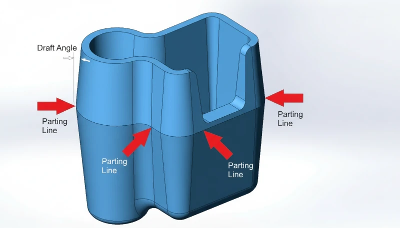
Toda peça injetada tem uma — essa linha fina que corre pela superfície onde as metades do molde se encontram. O linha de separação1 não é um defeito; é uma característica inevitável da moldagem por injeção processo. Mas onde você coloca ela, e como você designa em torno dela, pode fazer a diferença entre uma peça pronta para produção e um redesign custoso.
Na nossa oficina de moldes, vimos engenheiros errar a linha de separação mais vezes do que conseguimos contar. Parece simples — basta dividir o molde ao meio — até perceber que a linha de separação determina exatamente onde flash2 aparece, quais dimensões são mantidas com uma tolerância rigorosa, se a peça pode ser adequadamente ejectada do molde, e quanto custará a ferramentaria. Este guia aborda tudo que os engenheiros precisam saber sobre superfícies de separação e linhas de separação para que possa fazer corretamente desde a primeira vez.
- A linha de separação é o traço físico deixado onde duas metades do molde se encontram durante a injecção.
- O desenho da superfície de separação impacta diretamente a qualidade da peça, o custo do molde e a eficiência de produção.
- Cinco tipos principais: superfícies de separação planas, escalonadas, anguladas, curvas e compostas.
- Análise DFM antes da ferramentaria pode prevenir 80% de problemas de produção relacionados com linha de separação.
- O rebarbado na linha de separação é controlado pela precisão do molde, força de fecho e seleção de material.

What Is a Parting Surface in Injection Molding?
Uma superfície de separação é a interface plana ou contornada onde duas metades do molde se encontram e selam durante a injecção. Se está comparando fornecedores ou planeando procurement, nosso injection molding supplier sourcing guide covers RFQ prep, qualification, and commercial risk checks.
Uma superfície de separação é a interface de contacto entre duas metades do molde — o lado da cavidade (lado A) e o lado do núcleo (lado B). Quando o molde fecha, estas duas superfícies pressionam-se juntas sob toneladas de força de fecho. A linha de separação é o traço estreito que esta interface deixa na peça plástica acabada.
Num sentido restrito, a superfície de separação refere-se especificamente ao plano principal de separação no maior contorno da peça — a superfície que divide a cavidade do núcleo. Num sentido mais amplo, inclui todas as superfícies de contacto entre módulos do molde: faces de cursor, interfaces de elevador, juntas de inserção e assentos de pinos ejetores. Cada uma destas interfaces pode deixar uma linha visível na peça.
Os profissionais da indústria frequentemente chamam-lhe "superfície PL" ou "linha PL", para abreviar. A espessura e visibilidade desta linha dependem da precisão do molde, da força de fecho, da viscosidade do material e das condições de processamento. Uma superfície de separação bem projetada, com tolerâncias apertadas do molde, produz uma linha tão fina que é quase invisível — tipicamente com 0,01 a 0,05 mm de largura. Uma mal projetada produz rebarbas visíveis, desalinhamentos ou marcas de degrau que exigem operações secundárias de aparagem.
Como é Formada a Linha de Separação Durante a Moldagem?
A linha de separação é formada quando duas metades do molde se fecham sob a força de aperto, criando uma costura física na peça acabada. Um molde de injeção consiste em pelo menos duas metades — uma metade fixa montada no plato fixo e uma metade móvel montada no plato móvel. Quando a máquina de moldagem fecha o molde, as duas metades encontram-se na superfície de separação.
Durante a injecção, plástico fundido preenche a cavidade sob alta pressão (tipicamente 500–2,000 bar). Parte desta pressão actua directamente na superfície de separação. Mesmo com faces do molde rectificadas com precisão, existe um espaço microscópico entre as metades. Se a pressão de injecção excede o que a força de fecho pode conter, o material força entrada neste espaço — isso é rebarba.
Após o arrefecimento e solidificação, o molde abre ao longo do plano de separação. A peça permanece no lado do núcleo (devido à retração que agarra o núcleo), e o sistema ejector empurra-a para libertar. A junta onde as duas metades do molde se encontraram está agora permanentemente registada na superfície da peça como a linha de separação.

Na maioria dos casos, a linha de separação é perpendicular à direção de abertura do molde. Mas para geometrias complexas — peças com reentrâncias, características laterais ou perfis assimétricos — a superfície de separação pode incluir secções escalonadas, anguladas ou curvadas. Estas superfícies de separação multidirecionais requerem mecanismos adicionais no molde, como guias, elevadores ou pinos angulados, para funcionar correctamente.
"Uma largura de linha de separação de 0,01 mm é considerada aceitável para a maioria das peças cosméticas."Verdadeiro
Para superfícies visíveis/cosméticas, linhas de separação abaixo de 0.05 mm são geralmente aceitáveis. Moldes de alta precisão podem atingir 0.01 mm ou menos, que é quase invisível ao olho nu.
“A linha de separação é um defeito causado por fabricação deficiente do molde.”Falso
A linha de separação é uma característica inevitável de qualquer molde de duas partes. Ela existe em todas as peças moldadas por injecção, independentemente da qualidade do molde. O que varia é a visibilidade da linha — um molde de precisão produz uma linha quase imperceptível, enquanto um molde desgastado ou mal projetado produz rebarbas visíveis.
Quais São os Tipos de Superfícies de Separação?
Os cinco tipos de superfícies de separação são planas, escalonadas, anguladas, curvadas e compostas. Escolher o tipo adequado é uma das primeiras e mais importantes decisões no design do molde. Eis as cinco principais categorias:
Superfície de Separação Plana (Reta)
O tipo mais simples e comum. A superfície de separação é um único plano plano perpendicular à direção de abertura do molde. Funciona bem para peças em forma de copo, painéis planos e qualquer geometria onde a maior secção transversal é um plano horizontal limpo. Superfícies de separação planas são as mais fáceis de maquinar, selar e manter — o que traduz directamente em custo inferior do molde e qualidade de peça mais consistente.
Superfície de Separação Escalonada
Quando uma peça tem características em alturas diferentes que não podem ser acomodadas por um único plano plano, a superfície de separação sobe ou desce em degraus para seguir o contorno da peça. As superfícies de separação escalonadas criam forças laterais durante a injecção que o molde deve resistir — tipicamente usando características de encaixe ou insertos em forma de cunha. Se a altura do degrau for excessiva, os projetistas adicionam almofadas para achatar parcialmente a superfície, mantendo o afastamento necessário.
Superfície de Separação Angulada (Inclinada)
Para peças com características angulares ou perfis assimétricos, a superfície de separação segue um plano inclinado. A superfície angular inclui uma secção de vedação ao longo da inclinação (para conter o plástico) e uma secção de referência plana (para maquinação, alinhamento e medição). Este tipo requer atenção cuidadosa à gestão da força lateral — a pressão de injecção cria um impulso lateral que deve ser equilibrado.
Superfície de Separação Curvada (Contornada)
Os produtos de consumo complexos — pense em caixas de ferramentas elétricas, revestimentos interiores automóveis ou invólucros de dispositivos médicos — muitas vezes necessitam de superfícies de separação que sigam os contornos curvos da peça. A face do molde é maquinada por CNC para coincidir com o perfil 3D. As superfícies de separação curvas exigem alta precisão de maquinação e um desenho cuidadoso da superfície de vedação para evitar rebarbas ao longo de todo o contorno.
Superfície de Separação Composta (Combinada)
Muitas peças reais combinam dois ou mais dos tipos acima. Um molde único pode ter uma secção plana numa área, um degrau noutra e uma secção curva noutro local. As superfícies de separação compostas exigem atenção extra nas zonas de transição — os cantos vivos na junção entre diferentes tipos de superfície devem ser suavizados para evitar aço do molde frágil e impedir rebarbas.
Quais são os Princípios de Design Cruciais da Superfície de Separação?
Um bom design da superfície de separação é governado por um conjunto de princípios práticos que equilibram qualidade da peça, custo do molde e fiabilidade da produção. Nos nossos 20+ anos de fabricação de moldes, estas são as regras que separam uma produção fluída de semanas de modificações do molde.
Princípio 1: Garantir uma Desmoldagem Adequada
A superfície de separação principal deve estar localizada na maior secção transversal da peça na direção de abertura do molde. Esta é a regra fundamental. Colocar a linha de separação noutro local qualquer significa que serão necessárias ações laterais (carrinhos, extractores) para libertar a peça — acrescentando custo, complexidade e pontos de manutenção ao molde. Cada ação lateral adicional é outra fonte potencial de rebarbas, desgaste e tempo de inatividade.
Princípio 2: Manter a Peça no Lado Correto
Como o sistema de ejeção está na metade móvel do molde (lado B), a superfície de separação deve ser projetada para que a peça permaneça no núcleo após a abertura do molde. Se a peça ficar presa na cavidade (lado A), será necessário um mecanismo de ejeção dedicado na metade fixa — aumentando custos e complexidade. Ângulos de saída no lado do núcleo e características de rebaixo ajudam a garantir uma retenção confiável da peça.
Princípio 3: Preservar a Precisão Dimensional
Qualquer dimensão que atravesse a linha de separação está sujeita a variações devido ao alinhamento do molde, à deflexão do fecho e à formação de rebarbas. Para dimensões críticas — especialmente aquelas que requerem co-axialidade apertada ou tolerância posicional — coloque todas as características relacionadas no mesmo lado do molde. Um furo escalonado que exija uma co-axialidade de ±0,02 mm deve ser formado por um único núcleo numa das metades do molde, e não dividido pelas duas.
Princípio 4: Optimizar Ventilação
O ar aprisionado na cavidade causa queimaduras, peças incompletas e linhas de solda fracas. A superfície de separação deve ser posicionada de modo que a frente de fusão atinja a linha de separação por último — permitindo que o ar escape através da folga natural entre as metades do molde. Se a superfície de separação selar antes da cavidade estar cheia, o ar fica aprisionado em regiões sem saída sem caminho de escape.
Princípio 5: Simplificar a Construção do Molde
Cada complexidade adicional na superfície de separação acrescenta tempo de maquinação, custo de inspeção e risco de manutenção. Se a geometria da peça o permitir, uma superfície de separação plana é sempre preferível. Quando a complexidade é inevitável — como superfícies escalonadas ou curvas — tente combinar múltiplas características em superfícies partilhadas para reduzir o número total de transições de separação.
“As dimensões que cruzam a linha de separação têm mais variação do que as dimensões numa metade do molde.”Verdadeiro
Qualquer dimensão que abranja ambas as metades do molde é afetada pela precisão do alinhamento do molde, consistência da força de fecho, diferenças de expansão térmica e espessura do rebarbado. Manter tolerâncias apertadas (±0,05 mm ou melhor) ao longo da linha de separação é significativamente mais difícil do que numa única metade do molde.
“Uma superfície de separação escalonada requer sempre mecanismos de extração de núcleos laterais.”Falso
As superfícies de separação escalonadas acompanham as alterações de altura na geometria da peça, mas ainda abrem na direção principal do molde. É necessário extração de núcleos laterais (carrinhos) para reentrâncias — características que são perpendiculares à direção de abertura do molde. Um degrau pode existir sem qualquer reentrância.
Como a Localização da Linha de Separação Afeta a Qualidade da Peça?
A localização da linha de separação é, sem dúvida, a decisão mais impactante no design do molde. Afeta diretamente quatro dimensões de qualidade: aparência, precisão dimensional, acabamento superficial e longevidade da ferramentaria.
Aparência: Em superfícies cosméticas, a linha de separação é uma costura visível. Para produtos de consumo, isto significa que a linha de separação deve estar escondida numa área não visível, disfarçada ao longo da borda de uma característica, ou acabada para quase invisibilidade. Se a sua peça tem uma superfície Classe A visível, a linha de separação precisa de estar na parte de trás ou ao longo de uma linha de quebra natural. Trabalhámos com clientes automóveis que rejeitaram lotes de produção inteiros porque a linha de separação se deslocou 0,2 mm da posição acordada.
Precisão dimensional: Como discutido acima, as dimensões que cruzam a linha de separação herdam a tolerância de alinhamento do molde. Para peças com tolerâncias gerais de ±0,1 mm, isto é normalmente gerível. Para componentes de precisão com requisitos de ±0,02 mm, é necessário evitar completamente a divisão de características críticas pela linha de separação.
Acabamento da superfície: A área da linha de separação tem tipicamente uma textura superficial diferente do resto da peça. Mesmo com moldes polidos, a junção onde as duas metades se encontram cria um ligeiro degrau ou linha de testemunho. Se a peça requer um acabamento SPI específico (como SPI A-2 para superfícies de qualidade de lente), a área da linha de separação nunca corresponderá perfeitamente ao acabamento circundante.
Longevidade do ferramental: As superfícies de separação suportam a força total do fecho ciclo após ciclo. Uma superfície de separação bem projetada, com suporte adequado e área de apoio suficiente, durará centenas de milhares de ciclos. Uma mal projetada — com arestas vivas, área de vedação insuficiente ou saliência excessiva — desgastar-se-á, amassar-se-á e desenvolverá rebarbado em dezenas de milhares de ciclos.
Quando Se Deve Usar Superfícies de Separação Escalonadas ou Curvas?
Superfícies de separação escalonadas são utilizadas quando uma peça tem características a diferentes alturas, e superfícies curvas são necessárias para geometria não planar. Eis quando usar cada tipo e que compromissos se aceita.
Use uma superfície de separação escalonada quando: A peça tem características em alturas significativamente diferentes que não podem ser desmoldadas com um único plano plano. Caixas de eletrónica com cortes para conectores em alturas diferentes, metades de invólucros com reforços de montagem escalonados e componentes de bomba com múltiplos níveis de vedação são candidatos típicos. A principal preocupação de engenharia com superfícies escalonadas é gerir as forças de injeção laterais — a pressão da fusão empurra lateralmente no degrau, e sem interlocks ou apoios em cunha adequados, as metades do molde podem deslocar-se, causando deriva dimensional e rebarba.
Use uma superfície de separação curva quando: A peça tem geometria orgânica e não planar — pense em invólucros de produtos de consumo, guarnições automóveis ou pegas ergonómicas. A superfície de separação segue o contorno 3D da peça para ocultar a linha ao longo de uma aresta natural ou limite de característica. Esta abordagem produz os melhores resultados cosméticos, mas exige maquinagem CNC de alta precisão e texturização cuidadosa do molde para garantir que o acabamento superficial seja consistente através da interface curva.
Análise de compromisso: Passar de superfícies planas para escalonadas e depois para curvas, cada passo adiciona aproximadamente 15–30% ao custo de construção do molde. Superfícies escalonadas exigem maquinagem adicional de intertravamento e, potencialmente, bases de molde maiores. Superfícies curvas exigem trabalho CNC de 5 eixos e tempo de ajuste prolongado. A penalização na produção também é real — superfícies de separação complexas desgastam-se mais rapidamente, necessitam de manutenção mais frequente e são mais sensíveis à deriva dos parâmetros do processo.
“Superfícies de separação curvas são sempre mais caras de fabricar do que as planas.”Verdadeiro
Superfícies de separação curvas requerem maquinação CNC de 5 eixos, tempo de ajuste/assentamento estendido e inspeção mais complexa. Uma superfície de separação plana pode ser retificada superficialmente para tolerância rapidamente, enquanto uma curva deve ser maquinada e ajustada manualmente ao longo de todo o contorno. O custo adicional é tipicamente 20–40% superior a um design plano comparável.
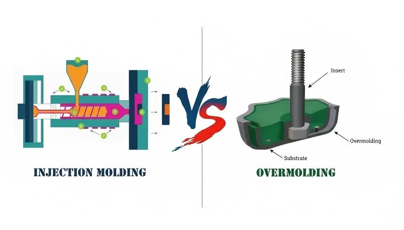
“Pode eliminar completamente a linha de separação utilizando moldação por inserção.”Falso
A moldação por inserção ainda utiliza um molde de duas partes e, portanto, ainda produz uma linha de separação. O inserto é colocado no molde antes da injeção, mas o molde ainda abre e fecha ao longo de uma superfície de separação. A única forma de evitar uma linha de separação é utilizar um processo sem molde dividido, como maquinagem a partir de material sólido.
Como Pode a Análise DFM Otimizar a Sua Linha de Separação?
Design para Fabrico (DFM3) é a sua melhor ferramenta para acertar a linha de separação antes de qualquer aço ser cortado. No nosso fluxo de trabalho de DFM na fábrica, mapeamos a decisão de separação contra as etapas da moldação por injeção para que a linha de separação suporte o enchimento, compactação, arrefecimento, ejeção e inspeção. Uma revisão completa de DFM avalia a geometria da peça, identifica a localização ótima da linha de separação, sinaliza potenciais problemas de desmoldagem e estima a complexidade do molde necessária.
Na ZetarMold, os nossos 8 engenheiros seniores trazem cada um mais de 10 anos de experiência em design de moldes para cada revisão DFM. Nos nossos testes de ferramental, os nossos engenheiros de processo também comparam a rebarba da linha de separação com a consistência da fusão da máquina de moldagem por injeção de parafuso, porque uma frente de fusão instável pode fazer uma superfície de separação marginal parecer pior do que realmente é. Eis o que uma análise DFM adequada da linha de separação abrange:
1. Identificação de reentrâncias: Cada característica de reentrância é catalogada. Para cada uma, determinamos se necessita de um cursor, elevador, núcleo recolhível ou pode ser resolvida simplesmente relocalizando a linha de separação. Em muitos casos, um ligeiro redesenho da característica de reentrância elimina completamente a necessidade de uma ação lateral — poupando custos significativos de ferramentaria.
2. Verificação do ângulo de saída: Todas as superfícies perpendiculares à linha de separação necessitam de ângulo de saída adequado — tipicamente 1–3°, dependendo do material e do acabamento superficial. Paredes com ângulo de saída zero ou negativo perto da linha de separação causarão aderência, riscos ou falhas de ejeção.
3. Avaliação do risco de rebarbado: Avaliamos quais áreas da superfície de separação enfrentarão a maior pressão de fusão e se o molde tem área de apoio suficiente para a conter. Secções de parede fina perto da linha de separação são zonas de alto risco para rebarbado.
Na nossa fábrica de Xangai, operamos 47 máquinas de moldação por injeção, desde 90T a 1850T, apoiadas por uma instalação interna de fabrico de moldes. Cada ferramenta que construímos passa por uma verificação rigorosa da linha de separação — porque mesmo um desalinhamento de 0,05 mm pode causar rebarbado visível na peça final.
“O nylon (PA) requer tolerâncias de linha de separação mais apertadas do que o policarbonato (PC) devido à sua menor viscosidade de fusão.”Verdadeiro
O nylon tem uma viscosidade de fusão muito mais baixa do que o policarbonato, o que significa que flui mais facilmente para fendas microscópicas na superfície de separação. Isto torna as peças de nylon mais propensas a rebarbado, exigindo ajustes mais apertados do molde (tipicamente 0,02 mm ou menos) em comparação com o policarbonato (0,05 mm ou menos).
“Uma análise DFM só é necessária para peças complexas ou de alto volume.”Falso
A análise DFM é valiosa para todas as peças injetadas, independentemente da complexidade ou volume. Mesmo peças simples podem ter problemas na linha de separação que são baratos de corrigir na fase de projeto, mas caros de corrigir após a construção do molde. Uma revisão DFM de 30 minutos pode poupar milhares em modificações do molde.
Perguntas mais frequentes
O que causa rebarba visível ao longo da linha de separação?
A rebarba forma-se quando o plástico fundido escapa através do espaço entre as metades do molde na superfície de separação durante a fase de injeção. Causas comuns incluem força de fecho insuficiente em relação à pressão de injeção, faces do molde desgastadas ou danificadas que já não vedam hermeticamente, mau alinhamento do molde que causa pressão de apoio desigual, pressão de embalagem excessiva mantida por demasiado tempo e materiais de baixa viscosidade, como o nylon, que fluem facilmente para pequenos espaços. A manutenção regular do molde — incluindo o reajuste das superfícies de separação a cada 50.000–100.000 ciclos — combinada com o controlo adequado dos parâmetros do processo e tonelagem suficiente da máquina são as principais defesas contra a rebarba na linha de separação.
Pode uma linha de separação ser completamente eliminada de uma peça moldada por injeção?
Não, não pode. Cada peça moldada por injeção produzida com um molde convencional de duas partes terá sempre uma linha de separação onde as metades da cavidade e do núcleo se encontram. O objetivo não é a eliminação, mas a minimização — através da construção de moldes de precisão com superfícies de separação retificadas, colocação estratégica da linha de separação em superfícies não cosméticas e parâmetros de processamento otimizados. Para aplicações onde qualquer costura visível é inaceitável, processos de fabricação alternativos, como usinagem CNC a partir de blocos maciços ou fabricação aditiva, podem produzir peças sem costuras, embora a um custo por peça significativamente mais alto e com menor capacidade de produção.
Quão fina pode ser feita uma linha de separação?
Com um molde retificado de precisão usando aço-ferramenta temperado (HRC 48–52), as linhas de separação podem ser reduzidas a uma largura de 0,005–0,01 mm — praticamente invisíveis a olho nu e indetetáveis ao toque. Os moldes de produção padrão normalmente produzem linhas de 0,02–0,05 mm, que são visíveis mas aceitáveis para a maioria das aplicações não cosméticas. A finura alcançável depende de vários fatores: precisão da usinagem do molde (retificação superficial vs. fresagem), dureza e resistência ao desgaste do aço, adequação da força de fecho, perfil de pressão de injeção e a viscosidade do fundido do material de moldagem. Moldes de maior precisão custam mais, mas proporcionam linhas de separação consistentemente mais finas ao longo de séries de produção mais longas.
Qual é a diferença entre uma superfície de separação e uma linha de separação?
A superfície de separação é toda a interface de acoplamento entre as duas metades do molde — é uma superfície 2D ou 3D dentro da própria ferramenta do molde. A linha de separação é o traço estreito 1D que esta interface deixa na superfície da peça plástica moldada após a ejeção. Por outras palavras, a superfície de separação é uma característica de design do molde que existe no aço da ferramenta, enquanto a linha de separação é a evidência visível dessa superfície transferida para a peça acabada. Uma única superfície de separação pode produzir uma linha de separação complexa e sinuosa se a geometria do molde incluir secções escalonadas, anguladas ou curvas.
A localização da linha de separação afeta o custo da moldagem por injeção?
Sim, significativamente. Uma superfície de separação plana simples é a mais económica para ferramentar, maquinar e manter. Cada aumento de complexidade — escalonar a superfície, adicionar curvas ou introduzir interfaces de separação adicionais — aumenta o tempo de maquinação, a mão-de-obra de ajuste, os requisitos de inspeção e o custo de manutenção a longo prazo. Passar de uma superfície plana para uma superfície de separação composta tipicamente aumenta o custo do molde em 30–50%. Linhas de separação que requerem ações laterais, como deslizadores, elevadores ou pinos angulados, acrescentam ainda mais custo, uma vez que cada ação lateral requer o seu próprio sistema de guia, placa de desgaste e mecanismo de retorno, além de ajuste e testes adicionais durante a comissionamento do molde.
Que ângulo de saída é necessário perto da linha de separação?
Um mínimo de 1° de saída por lado é recomendado para todas as superfícies perpendiculares à linha de separação na moldagem de produção padrão. Para peças com superfícies texturizadas (como acabamentos MT, VDI ou por erosão por faísca), são necessários 1,5–3° por lado — texturas mais profundas precisam de mais saída para evitar que a textura seja arranhada durante a ejeção. Superfícies polidas ou com acabamento espelhado podem funcionar com apenas 0,5° de saída. Paredes com saída zero ou negativa perto da linha de separação arriscam a peça a ficar presa, arranhões na superfície durante a ejeção, aumento das marcas dos pinos ejetores e variação dimensional de ciclo para ciclo. A saída deve ser especificada durante o design da peça, não descoberta como um problema durante o teste do molde.
Como é que a força de fecho se relaciona com a qualidade da linha de separação?
A força de fecho da máquina de moldagem deve exceder a força total de separação gerada pela pressão de injeção que actua na área projetada da superfície de separação. Se a força de fecho é insuficiente, o molde abre-se ligeiramente durante as fases de injeção e compactação, criando uma abertura que permite que o plástico escape como rebarba ao longo da linha de separação. A força de fecho necessária é calculada como: pressão de injeção × área projetada da cavidade × factor de segurança (tipicamente 1.1–1.2). Operar um molde numa máquina de dimensão insuficiente é a causa mais comum de rebarba na linha de separação em ambientes de produção. Selecionar a tonelagem adequada da máquina durante o planeamento da produção é essencial para uma qualidade consistente da linha de separação.
A nossa equipa de engenharia na ZetarMold traz mais de 20 anos de experiência em design de moldes, 8 engenheiros seniores e uma instalação de fabrico de moldes interna para cada projeto. Desde a análise DFM até à produção, otimizamos a sua linha de separação para qualidade, custo e desempenho. Com 47 máquinas de moldagem por injeção (90T-1850T) e mais de 400 materiais plásticos, tratamos de tudo, desde componentes óticos de precisão até peças estruturais grandes.
Request a Free Quote →
-
linha de separação: linha de separação refere-se à linha visível numa peça moldada onde as duas metades do molde se encontram durante o processo de moldagem por injeção. ↩
-
flash: rebarba refere-se ao excesso de material que escapa da cavidade do molde na linha de separação durante a injeção, formando bordas finas indesejadas. ↩
-
DFM: DFM refere-se a design for Manufacturing — a prática de projetar componentes para que sejam mais fáceis e econômicos de produzir. ↩


