Ogni componente stampato a iniezione ne presenta una: quella sottile linea che corre sulla superficie nel punto in cui si incontrano le due metà dello stampo. La linea di divisione1 non è un difetto, ma una caratteristica inevitabile del processo di stampaggio a iniezione. Tuttavia, la sua posizione e il modo in cui viene integrata nel progetto possono fare la differenza tra un componente pronto per la produzione e una costosa riprogettazione.
Nella nostra officina stampi abbiamo visto ingegneri sbagliare la linea di divisione innumerevoli volte. Sembra semplice — basta dividere lo stampo a metà — finché non ci si rende conto che la linea di divisione determina esattamente dove compare la bava2, quali quote rispettano tolleranze strette, se il componente può essere espulso correttamente dallo stampo e quanto costerà l’attrezzatura. Questa guida illustra tutto ciò che gli ingegneri devono sapere su superfici e linee di divisione per impostarle correttamente fin dall’inizio.
- La linea di divisione è la traccia fisica lasciata nel punto in cui le due metà dello stampo si incontrano durante l'iniezione.
- La progettazione della superficie di divisione influisce direttamente sulla qualità del pezzo, sul costo dello stampo e sull'efficienza produttiva.
- Cinque tipi principali: superfici di separazione piane, a gradini, inclinate, curve e composite.
- L’analisi DFM prima dell’attrezzaggio può prevenire l’80% dei problemi produttivi legati alla linea di divisione.
- La bava sulla linea di divisione è controllata dalla precisione dello stampo, dalla forza di chiusura e dalla selezione del materiale.
Che cos’è una superficie di divisione nello stampaggio a iniezione?
Una superficie di divisione è l’interfaccia piana o sagomata lungo la quale le due metà dello stampo si incontrano e assicurano la tenuta durante l’iniezione. Se state confrontando fornitori o pianificando gli acquisti, la nostra guida all’approvvigionamento dei fornitori di stampaggio a iniezione tratta la preparazione delle richieste di offerta, la qualifica e i controlli dei rischi commerciali.
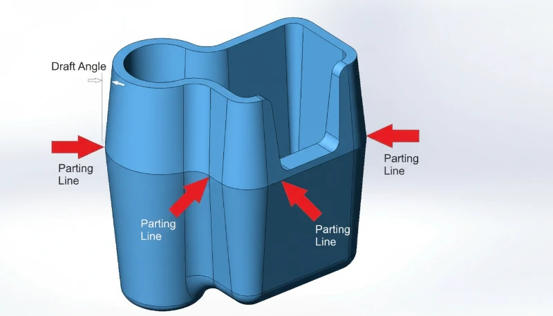
Una superficie di divisione è l’interfaccia di contatto tra le due metà dello stampo: il lato cavità (lato A) e il lato anima (lato B). Quando lo stampo si chiude, queste due superfici vengono premute l’una contro l’altra da tonnellate di forza di chiusura. La linea di divisione è la sottile traccia lasciata da questa interfaccia sul pezzo di plastica finito.
In senso stretto, la superficie di separazione indica specificamente il piano principale di divisione in corrispondenza del contorno più ampio del pezzo, ossia la superficie che separa la cavità dal nucleo. In senso più ampio, comprende tutte le superfici di contatto tra i moduli dello stampo: facce delle slitte, interfacce degli estrattori inclinati, giunti degli inserti e sedi dei perni di espulsione. Ognuna di queste interfacce può lasciare una linea visibile sul pezzo.
I professionisti del settore la chiamano spesso “superficie PL” o “linea PL”. Spessore e visibilità dipendono da precisione dello stampo, forza di chiusura, viscosità del materiale e condizioni di processo. Una superficie di divisione ben progettata e tolleranze strette producono una linea quasi invisibile — tipicamente larga 0.01–0.05 mm. Una progettazione scadente produce bave, disallineamenti o gradini visibili che richiedono rifilatura secondaria.
Come si forma la linea di divisione durante lo stampaggio?
La linea di divisione si forma quando le due metà dello stampo si chiudono sotto la forza di serraggio, creando una giunzione fisica sul componente finito. Uno stampo a iniezione è costituito da almeno due metà: una fissa, montata sul piano fisso, e una mobile, montata sul piano mobile. Quando la pressa chiude lo stampo, le due metà si incontrano sulla superficie di divisione.
Durante l’iniezione, la plastica fusa riempie la cavità ad alta pressione (in genere 500–2,000 bar). Parte di questa pressione agisce direttamente sulla superficie di divisione. Anche con facce rettificate di precisione, esiste un’intercapedine microscopica tra le metà. Se la pressione di iniezione supera la forza di chiusura disponibile, il materiale penetra in questa fessura: questa è la bava.
Dopo il raffreddamento e la solidificazione, lo stampo si apre lungo il piano di divisione. Il pezzo rimane sul lato dell’anima (grazie al ritiro che lo fa aderire all’anima) e il sistema di espulsione lo libera. La giunzione in cui si incontravano le due metà dello stampo rimane impressa in modo permanente sulla superficie del pezzo come linea di divisione.
Nella maggior parte dei casi, la linea di divisione è perpendicolare alla direzione di apertura dello stampo. Tuttavia, per geometrie complesse — pezzi con sottosquadri, caratteristiche laterali o profili asimmetrici — la superficie di divisione può includere sezioni a gradino, inclinate o curve. Queste superfici di divisione multidirezionali richiedono meccanismi aggiuntivi dello stampo, come slitte, estrattori inclinati o perni inclinati, per funzionare correttamente.
"Una larghezza della linea di divisione di 0,01 mm è considerata accettabile per la maggior parte dei pezzi estetici."True
Per le superfici visibili/estetiche, linee di divisione inferiori a 0.05 mm sono generalmente accettabili. Gli stampi ad alta precisione possono raggiungere 0.01 mm o meno, un valore quasi invisibile a occhio nudo.
"La linea di divisione è un difetto causato da una fabbricazione inadeguata dello stampo."False
La linea di divisione è una caratteristica inevitabile di qualsiasi stampo in due metà. È presente su ogni pezzo stampato a iniezione, indipendentemente dalla qualità dello stampo. A variare è la sua visibilità — uno stampo di precisione produce una linea appena percettibile, mentre uno stampo usurato o mal progettato genera bava visibile.
Quali sono i tipi di superfici di divisione?
I cinque tipi di superfici di separazione sono: piana, a gradini, inclinata, curva e composita. Scegliere il tipo giusto è una delle prime e più importanti decisioni nella progettazione dello stampo. Ecco le cinque categorie principali:
Superficie di divisione piana (rettilinea)
È il tipo più semplice e comune. La superficie di divisione è un unico piano piatto perpendicolare alla direzione di apertura dello stampo. È adatto a pezzi a forma di coppa, pannelli piatti e qualsiasi geometria in cui la sezione trasversale più grande sia un piano orizzontale netto. Le superfici di divisione piane sono le più facili da lavorare, sigillare e manutenere — traducendosi direttamente in costi inferiori dello stampo e qualità più uniforme dei pezzi.
Superficie di divisione a gradini
Quando il pezzo presenta caratteristiche ad altezze diverse incompatibili con un unico piano, la superficie di divisione sale o scende seguendone il profilo. Le superfici a gradini creano forze laterali durante l’iniezione, contrastate generalmente con incastri o inserti a cuneo. Se l’altezza è eccessiva, si aggiungono tamponi per appiattire parzialmente la superficie mantenendo il gioco necessario.
Superficie di divisione angolata (inclinata)
Per pezzi con elementi inclinati o profili asimmetrici, la superficie di divisione segue un piano inclinato. La superficie inclinata comprende una sezione di tenuta lungo la pendenza (per contenere la plastica) e una sezione di riferimento piana (per lavorazione, allineamento e misurazione). Questo tipo richiede particolare attenzione alla gestione delle forze laterali: la pressione di iniezione crea una spinta laterale che deve essere bilanciata.
Superficie di divisione curva (sagomata)
I prodotti di consumo complessi, come alloggiamenti per elettroutensili, rivestimenti interni per automobili o involucri di dispositivi medicali, richiedono spesso superfici di divisione che seguano i contorni curvi del pezzo. La faccia dello stampo viene lavorata a CNC per corrispondere al profilo 3D. Le superfici di divisione curve richiedono un’elevata precisione di lavorazione e un’attenta progettazione delle superfici di tenuta per prevenire la bava lungo l’intero contorno.
Superficie di divisione composita (combinata)
Molti pezzi reali combinano due o più dei tipi descritti sopra. Un singolo stampo può avere una sezione piana in un’area, un gradino in un’altra e una sezione curva altrove. Le superfici di divisione composite richiedono particolare attenzione nelle zone di transizione: gli spigoli vivi nella giunzione tra tipi di superficie diversi devono essere raccordati per evitare zone deboli nell’acciaio dello stampo e prevenire le bave.
Quali sono i principi fondamentali di progettazione della superficie di divisione?
Una buona progettazione della superficie di divisione è governata da principi pratici che bilanciano qualità del pezzo, costo dello stampo e affidabilità produttiva. Nei nostri oltre 20 anni di costruzione stampi, queste sono le regole che distinguono una produzione regolare da settimane di modifiche allo stampo.
Principio 1: garantire uno sformo corretto
La superficie di divisione principale deve trovarsi in corrispondenza della sezione massima del pezzo nella direzione di apertura dello stampo. È la regola fondamentale. Collocare altrove la linea di divisione richiede movimenti laterali (carrelli, sollevatori) per liberare il pezzo, aggiungendo costi, complessità e punti di manutenzione allo stampo. Ogni movimento laterale aggiuntivo è un’altra potenziale fonte di bava, usura e fermo macchina.
Principio 2: mantenere il pezzo sul lato corretto
Poiché il sistema di espulsione si trova sul semistampo mobile (B-side), la superficie di divisione deve essere progettata in modo che il pezzo rimanga sull’anima dopo l’apertura dello stampo. Se il pezzo resta aderente alla cavità (A-side), sarà necessario un meccanismo di espulsione dedicato sul semistampo fisso, con un aumento di costi e complessità. Gli angoli di sformo sul lato anima e i sottosquadri contribuiscono a garantire una ritenzione affidabile del pezzo.
Principio 3: preservare la precisione dimensionale
Qualsiasi dimensione che attraversi la linea di divisione è soggetta a variazioni dovute all’allineamento dello stampo, alla flessione in chiusura e alla formazione di bava. Per le dimensioni critiche, soprattutto quelle che richiedono coassialità o tolleranze di posizione strette, collocate tutti gli elementi correlati sullo stesso lato dello stampo. Un foro a gradino che richiede una coassialità di ±0.02 mm deve essere formato da un’unica anima su una metà dello stampo, non diviso tra entrambe.
Principio 4: ottimizzare la ventilazione
L’aria intrappolata nella cavità causa bruciature, riempimenti incompleti e linee di saldatura deboli. La superficie di separazione deve essere posizionata in modo che il fronte del fuso raggiunga per ultima la linea di divisione, consentendo all’aria di fuoriuscire attraverso il gioco naturale tra le due metà dello stampo. Se la superficie di separazione si chiude prima che la cavità sia piena, l’aria rimane intrappolata in zone cieche prive di vie di fuga.
Principio 5: semplificare la costruzione dello stampo
Ogni ulteriore complessità della superficie di divisione aumenta il tempo di lavorazione, il costo di ispezione e il rischio di manutenzione. Se la geometria del pezzo lo consente, è sempre preferibile una superficie di divisione piana. Quando la complessità è inevitabile, come nelle superfici a gradini o curve, cerca di combinare più caratteristiche in superfici condivise per ridurre il numero totale di transizioni della linea di divisione.
"Le dimensioni che attraversano la linea di divisione presentano variazioni maggiori rispetto a quelle situate su una sola metà dello stampo."True
Qualsiasi quota che attraversi entrambe le metà dello stampo è influenzata dalla precisione di allineamento, dall’uniformità della forza di chiusura, dalle differenze di dilatazione termica e dallo spessore della bava. Mantenere tolleranze strette (±0.05 mm o migliori) attraverso la linea di separazione è molto più difficile che su una singola metà dello stampo.
"Una superficie di separazione a gradini richiede sempre meccanismi di estrazione laterale dell'anima."False
Le superfici di divisione a gradini seguono le variazioni di altezza della geometria del pezzo, ma si aprono comunque nella direzione principale dello stampo. L'estrazione laterale dell'anima (slitte) è necessaria per i sottosquadri, ossia le caratteristiche perpendicolari alla direzione di apertura dello stampo. Può esistere un gradino senza alcun sottosquadro.
In che modo la posizione della linea di divisione influisce sulla qualità?
La posizione della linea di divisione è probabilmente la decisione con il maggiore impatto nella progettazione dello stampo. Influisce direttamente su quattro aspetti della qualità: aspetto, precisione dimensionale, finitura superficiale e durata dell’attrezzatura.
Aspetto: sulle superfici estetiche, la linea di divisione è una giunzione visibile. Nei prodotti di consumo deve quindi essere nascosta in un’area non visibile, dissimulata lungo il bordo di una caratteristica oppure rifinita fino a renderla quasi impercettibile. Se il componente presenta una superficie visibile di Classe A, la linea di divisione deve trovarsi sul retro o lungo una naturale linea di discontinuità. Abbiamo lavorato con clienti del settore automobilistico che hanno respinto interi lotti perché la linea di divisione si era spostata di 0,2 mm rispetto alla posizione concordata.
Precisione dimensionale: come già indicato, le quote che attraversano la linea di divisione ereditano la tolleranza di allineamento dello stampo. Per componenti con tolleranze generali di ±0,1 mm è in genere gestibile. Per componenti di precisione con requisiti di ±0,02 mm, invece, occorre evitare del tutto di suddividere caratteristiche critiche tra i due lati della linea di divisione.
Finitura superficiale: l’area della linea di divisione presenta normalmente una texture diversa dal resto del componente. Anche con stampi lucidati, la giunzione tra le due metà crea un leggero gradino o segno di riscontro. Se il componente richiede una finitura SPI specifica, come SPI A-2 per superfici di qualità ottica, l’area della linea di divisione non potrà mai corrispondere perfettamente alla finitura circostante.
Durata dell’attrezzatura: ciclo dopo ciclo, le superfici di divisione sopportano l’intera forza di serraggio. Una superficie ben progettata, con sostegno adeguato e un’area di appoggio sufficiente, resiste per centinaia di migliaia di cicli. Una superficie mal progettata, con spigoli vivi, area di tenuta insufficiente o sporgenze eccessive, si usura, si ammacca e sviluppa bave già dopo decine di migliaia di cicli.
Quando utilizzare superfici di divisione a gradini o curve?
Le superfici di separazione a gradini vengono utilizzate quando un componente presenta caratteristiche a diverse altezze e sono necessarie superfici curve per geometrie non piane. Ecco quando utilizzare ciascun tipo e quali compromessi si accettano.
Utilizzate una superficie di divisione a gradini quando il componente presenta caratteristiche ad altezze molto diverse che non possono essere sformate con un unico piano. Alloggiamenti elettronici con aperture per connettori a quote differenti, semigusci con risalti di montaggio sfalsati e componenti di pompe con più livelli di tenuta sono esempi tipici. La principale criticità ingegneristica è la gestione delle forze laterali di iniezione: la pressione del fuso spinge lateralmente sul gradino e, senza opportuni interblocchi o supporti a cuneo, le metà dello stampo possono spostarsi causando deriva dimensionale e bave.
Utilizzate una superficie di divisione curva quando il componente presenta una geometria organica e non planare, come negli alloggiamenti di prodotti di consumo, nei rivestimenti automobilistici o nelle impugnature ergonomiche. La superficie segue il profilo 3D del componente per nascondere la linea lungo un bordo naturale o il limite di una caratteristica. Questo approccio offre i migliori risultati estetici, ma richiede lavorazioni CNC ad alta precisione e un’accurata texturizzazione dello stampo per mantenere uniforme la finitura lungo l’interfaccia curva.
Analisi dei compromessi: passando da superfici di divisione piane a gradini e poi curve, ogni livello aggiunge indicativamente il 15–30% al costo di costruzione dello stampo. Le superfici a gradini richiedono lavorazioni aggiuntive degli interblocchi e, potenzialmente, basi stampo più grandi. Quelle curve esigono lavorazioni CNC a 5 assi e tempi di aggiustaggio più lunghi. Anche la penalizzazione produttiva è concreta: le superfici complesse si usurano più rapidamente, richiedono manutenzione più frequente e sono più sensibili alle variazioni dei parametri di processo.
"Le superfici di divisione curve sono sempre più costose da produrre rispetto a quelle piane."True
Le superfici di divisione curve richiedono lavorazione CNC a 5 assi, tempi prolungati di adattamento/riscontro e ispezioni più complesse. Una superficie di divisione piana può essere rettificata rapidamente entro tolleranza, mentre una curva deve essere lavorata e adattata manualmente lungo l’intero profilo. Il sovrapprezzo è in genere del 20–40% rispetto a un progetto piano comparabile.
"Con l'insert molding è possibile eliminare completamente la linea di divisione."False
Lo stampaggio con inserti utilizza comunque uno stampo in due parti e produce quindi una linea di divisione. L'inserto viene collocato nello stampo prima dell'iniezione, ma lo stampo continua ad aprirsi e chiudersi lungo una superficie di divisione. L'unico modo per evitare una linea di divisione consiste nell'utilizzare un processo senza stampo diviso, come la lavorazione da materiale pieno.
In che modo l’analisi DFM può ottimizzare la linea di divisione?
L’analisi Design for Manufacturing (DFM3) è lo strumento migliore per definire correttamente la linea di divisione prima di tagliare l’acciaio. Nel flusso DFM della nostra fabbrica, confrontiamo la decisione sulla divisione con le fasi dello stampaggio a iniezione, affinché la linea favorisca riempimento, mantenimento, raffreddamento, espulsione e ispezione. Un esame DFM approfondito valuta la geometria del componente, individua la posizione ottimale della linea di divisione, segnala potenziali problemi di sformatura e stima la complessità necessaria dello stampo.
Presso ZetarMold, i nostri 8 ingegneri senior portano ciascuno oltre 10 anni di esperienza nella progettazione di stampi in ogni revisione DFM. Nelle nostre prove di attrezzatura, i nostri ingegneri di processo confrontano anche lo sfrido della linea di separazione con la consistenza del fuso dalla macchina di stampaggio a iniezione a vite, perché un fronte di fusione instabile può far sembrare una superficie di separazione marginale peggiore di quanto non sia in realtà. Ecco cosa copre un’analisi DFM corretta della linea di separazione:
1. Individuazione dei sottosquadri: ogni caratteristica in sottosquadro viene catalogata. Per ciascuna si stabilisce se occorra un carrello, un estrattore inclinato, un’anima collassabile oppure se basti riposizionare la linea di divisione. In molti casi, una lieve riprogettazione del sottosquadro elimina completamente la necessità di un movimento laterale, con un notevole risparmio sui costi di attrezzaggio.
2. Verifica dell’angolo di sformo: tutte le superfici perpendicolari alla linea di divisione devono avere uno sformo adeguato, in genere 1–3° a seconda del materiale e della finitura. Pareti senza sformo o con sformo negativo vicino alla linea di divisione provocano incollaggi, rigature o problemi di espulsione.
3. Valutazione del rischio di bave: analizziamo quali aree della superficie di divisione saranno sottoposte alla massima pressione del fuso e se lo stampo dispone di un’area di appoggio sufficiente a contenerla. Le sezioni a parete sottile vicine alla linea di divisione sono zone ad alto rischio di formazione di bave.
Nel nostro stabilimento di Shanghai, operiamo 47 macchine per stampaggio a iniezione da 90T a 1850T, supportate da una struttura interna per la produzione di stampi. Ogni utensile che costruiamo passa attraverso una rigorosa verifica della linea di separazione — perché anche un disallineamento di 0,05 mm può causare evidenti sbavature sulla parte finale.

"Il nylon (PA) richiede tolleranze della linea di divisione più strette del policarbonato (PC) a causa della sua minore viscosità allo stato fuso."True
Il nylon ha una viscosità del fuso molto inferiore al policarbonato e scorre più facilmente negli interstizi microscopici della superficie di divisione. I pezzi in nylon sono quindi più soggetti a bava e richiedono accoppiamenti più stretti dello stampo (in genere 0,02 mm o meno) rispetto al policarbonato (0,05 mm o meno).
"Un’analisi DFM è necessaria solo per pezzi complessi o prodotti in grandi volumi."False
L'analisi DFM è utile per ogni componente stampato a iniezione, indipendentemente dalla complessità o dal volume. Anche i componenti semplici possono presentare problemi sulla linea di divisione, economici da risolvere in fase di progettazione ma costosi da correggere dopo la costruzione dello stampo. Una revisione DFM di 30 minuti può far risparmiare migliaia di euro in modifiche allo stampo.
Domande frequenti
Che cosa causa la bava visibile lungo la linea di divisione?
La bava si forma quando la plastica fusa fuoriesce attraverso lo spazio tra le due metà dello stampo sulla superficie di divisione durante la fase di iniezione. Tra le cause comuni figurano una forza di chiusura insufficiente rispetto alla pressione di iniezione, superfici dello stampo usurate o danneggiate che non garantiscono più una tenuta adeguata, un allineamento errato che causa una pressione di appoggio non uniforme, una pressione di mantenimento eccessiva applicata troppo a lungo e materiali a bassa viscosità, come il nylon, che penetrano facilmente nelle piccole fessure. La manutenzione regolare dello stampo, compreso il ripristino delle superfici di divisione ogni 50.000–100.000 cicli, insieme al corretto controllo dei parametri di processo e a un tonnellaggio adeguato della macchina, costituisce la principale difesa contro la bava sulla linea di divisione.
È possibile eliminare completamente la linea di divisione da un componente stampato a iniezione?
No, non è possibile. Ogni parte stampata a iniezione prodotta con uno stampo convenzionale in due metà avrà sempre una linea di divisione nel punto di incontro tra cavità e anima. L’obiettivo non è eliminarla, ma ridurla al minimo mediante una costruzione precisa dello stampo con superfici di divisione rettificate, un posizionamento strategico della linea su superfici non estetiche e parametri di processo ottimizzati. Per applicazioni in cui qualsiasi giunzione visibile è inaccettabile, processi produttivi alternativi come la lavorazione CNC da materiale pieno o la produzione additiva possono realizzare parti senza giunzioni, ma con un costo per parte notevolmente superiore e una produttività inferiore.
Quanto puo essere sottile una linea di divisione?
Con uno stampo rettificato di precisione che utilizza acciaio temprato per utensili (HRC 48–52), le linee di divisione possono essere ridotte a una larghezza di 0,005–0,01 mm, risultando praticamente invisibili a occhio nudo e impercettibili al tatto. Gli stampi di produzione standard generano generalmente linee di 0,02–0,05 mm, visibili ma accettabili per la maggior parte delle applicazioni non estetiche. Lo spessore ottenibile dipende da diversi fattori: precisione di lavorazione dello stampo (rettifica superficiale rispetto a fresatura), durezza e resistenza all’usura dell’acciaio, adeguatezza della forza di chiusura, profilo della pressione di iniezione e viscosità del fuso del materiale da stampare. Gli stampi di maggiore precisione costano di più, ma producono linee di divisione costantemente più sottili durante cicli di produzione più lunghi.
DFM si riferisce al design per la produzione — la pratica di progettare parti per renderle più facili ed economiche da produrre.
La superficie di divisione è l’intera interfaccia di accoppiamento tra le due metà dello stampo: una superficie 2D o 3D all’interno dello stampo stesso. La linea di divisione è la sottile traccia 1D che questa interfaccia lascia sulla superficie del pezzo plastico dopo l’espulsione. In altri termini, la superficie di divisione è un elemento progettuale presente nell’acciaio dello stampo, mentre la linea di divisione è l’evidenza visibile trasferita sul pezzo finito. Una singola superficie può produrre una linea complessa e sinuosa se la geometria comprende sezioni a gradino, inclinate o curve.
La posizione della linea di divisione influisce sul costo dello stampaggio a iniezione?
Sì, in misura significativa. Una superficie di divisione piana e semplice è la più economica da attrezzare, lavorare e mantenere. Ogni aumento di complessità, come gradini nella superficie, curve o ulteriori interfacce di divisione, aggiunge tempo di lavorazione, manodopera per l’aggiustaggio, requisiti di ispezione e costi di manutenzione a lungo termine. Il passaggio da una superficie piana a una composita aumenta in genere il costo dello stampo del 30–50%. Le linee di divisione che richiedono azioni laterali, come cursori, estrattori inclinati o perni angolati, aggiungono ancora più costi: ogni azione richiede il proprio sistema di guida, una piastra antiusura e un meccanismo di ritorno, oltre a ulteriore aggiustaggio e collaudo durante la messa in servizio dello stampo.
Quale angolo di sformo è necessario vicino alla linea di divisione?
Per lo stampaggio di produzione standard si consiglia almeno 1° di sformo per lato su tutte le superfici perpendicolari alla linea di divisione. Per componenti con superfici testurizzate, come finiture MT, VDI o elettroerose, sono necessari 1,5–3° per lato: le texture più profonde richiedono maggiore sformo per evitare sfregamenti durante l’espulsione. Per superfici lucidate o a specchio possono bastare 0,5°. Pareti con sformo nullo o negativo vicino alla linea di divisione rischiano di trattenere il pezzo, graffiarne la superficie durante l’espulsione, accentuare i segni degli estrattori e causare variazioni dimensionali da ciclo a ciclo. Lo sformo deve essere specificato durante la progettazione del componente, non scoperto come problema durante la prova stampo.
In che modo la forza di chiusura influisce sulla qualità della linea di divisione?
La forza di chiusura della pressa deve superare la forza totale di separazione generata dalla pressione di iniezione sull’area proiettata del piano di divisione. Se è insufficiente, lo stampo si apre leggermente durante iniezione e mantenimento, lasciando fuoriuscire plastica come bava. La forza richiesta si calcola come: pressione di iniezione × area proiettata della cavità × fattore di sicurezza (di norma 1.1–1.2). Usare una macchina sottodimensionata è la causa più comune di bava sulla linea di divisione. Scegliere il tonnellaggio corretto è essenziale per una qualità costante.
Il nostro team di ingegneria di ZetarMold porta oltre 20 anni di esperienza in design di stampi, 8 ingegneri senior e una struttura interna per la produzione di stampi in ogni progetto. Dall’analisi DFM alla produzione, ottimizziamo la tua linea di separazione per qualità, costo e performance. Con 47 macchine per stampaggio a iniezione (90T-1850T) e oltre 400 materiali plastici, gestiamo tutto, dai componenti ottici di precisione alle grandi parti strutturali.
Richiedete un preventivo gratuito →
linea di divisione: per linea di divisione si intende la linea visibile su un componente stampato nel punto in cui le due metà dello stampo si incontrano durante il processo di stampaggio a iniezione. ↩
bava: per bava si intende il materiale in eccesso che fuoriesce dalla cavità dello stampo lungo la linea di divisione durante l'iniezione, formando sottili bordi indesiderati. ↩
DFM: DFM significa Design for Manufacturing, ossia la pratica di progettare i componenti in modo che siano più semplici ed economici da produrre. ↩