 Overslaan naar inhoud

Het ontwerpen van spuitgietproducten is het werk van het omzetten van een nuttig productidee in geometrie die kan worden gevuld, gekoeld, uitgeworpen, gemonteerd en herhaald in productie. Een onderdeel kan er eenvoudig uitzien in CAD, maar toch zinkmarkeringen, sleepkrassen, ingesloten gas, uitstulpingen, gebroken uitwerperpennen of matrijsherwerking veroorzaken als het ontwerp de gereedschaps- en proceslimieten negeert.
Deze handleiding herbouwt de ontwerpprincipes voor spuitgietproducten rond productierealiteit. Het richt zich op wanddikte, ribben, trekhoek1, afsluitingen, tolerantie, materiaalgedrag en beoordelingsdiscipline, omdat die keuzes bepalen of een gereedschap stabiel draait nadat staal is gestanst.
Gebruik het vóór ontwerpbevriezing, niet na eerste shots. Wanneer onze fabriek een nieuw kunststofonderdeel beoordeelt, proberen we het matrijsrisico te vinden terwijl het nog een CAD-beslissing is, omdat een geometrische wijziging van 0,3 mm vóór gereedschap veel goedkoper is dan een gelaste insert of een noodstalen modificatie later.
- Ontwerpen voor spuitgieten begint met uniforme materiaalstroom, voorspelbare koeling en veilige uitwerping.
- Wanddikte, ribben, penanten en hoeken moeten worden gedimensioneerd als één verbonden systeem.
- Ontwerphelling en scheidingsstrategie moeten vóór gereedschap worden beoordeeld omdat ze het vrijkom- en uitstulpingsrisico beheersen.
- Tolerantie moet worden toegewezen op basis van functie en procescapaciteit, niet gekopieerd van gefreesde metaaltekeningen.
- Een korte DFM-beoordeling vóór de matrijsbouw voorkomt veel defecten in een laat stadium en kostenverrassingen.
Wat zijn de kernontwerpprincipes voor spuitgietproducten?
De kernontwerpprincipes voor spuitgietproducten zijn de belangrijkste categorieën of opties die in deze sectie worden uitgelegd. De kernontwerpprincipes voor spuitgietproducten zijn uniforme wanddikte, gebalanceerde stroomlengte, gecontroleerde koeling, betrouwbaar uitwerpen, realistische tolerantie en gereedschap-veilige geometrie. Deze principes werken samen omdat kunststof krimpt tijdens het afkoelen en omdat de matrijs het voltooide onderdeel moet kunnen vrijgeven zonder slepen of vervorming.
Begin door het onderdeel als een stroom- en koelprobleem te behandelen. Een poort kan gesmolten materiaal maar tot een bepaalde afstand duwen voordat druk, afschuiving en koeling het vulpatroon veranderen. Als één zone veel dikker is dan de rest, blijft die zone langer heet, krimpt later en veroorzaakt vaak zinkgaten, holtes of lokale vervorming.
De veiligste vroege beoordeling verbindt productfunctie met productiegrenzen. Een nuttige productspecificatie geeft aan welke oppervlakken cosmetisch zijn, welke afmetingen de montage beheersen, welke gebieden uitwerppunten kunnen accepteren en welke belastingen het onderdeel moet kunnen weerstaan. Die informatie stelt de ontwerper en matrijzenmaker in staat om geometrie, poortlocatie en materiaal af te wegen voordat de gereedschapslay-out vaststaat.
Voor een breder procesfundament, gebruik ZetarMold’s handleiding spuitgietproces. Voor gereedschapsbeslissingen zoals scheidingslijn, schuiven, lifters, koeling en staalveilige wijzigingen, koppel de beoordeling aan de injection mold guide. Als de koper een fabriek selecteert, de supplier sourcing guide helpt deze controles om te zetten in inkoopvragen.
“Een gespoten onderdeel moet worden ontworpen rond smeltstroom, koeling en uitstoting voordat cosmetische styling wordt vastgelegd.”Echt
Dit is waar omdat de matrijs niet elk geometrieprobleem kan corrigeren na het stansen van staal. Styling, ribben, penanten, clips en tolerantieopstapelingen beïnvloeden allemaal drukverlies, krimp, ontwerphelling en ontwerpkracht.
“Elk kunststofonderdeel kan dezelfde geometrie behouden als een CNC-gefreesd onderdeel als het materiaal sterk genoeg is.”Vals
Dit is onjuist omdat spuitgieten krimp, koelgradiënten, uitstootkrachten, scheidingsbeperkingen en poortresten toevoegt. Materiaalsterkte elimineert de noodzaak voor spuitgiet-specifieke geometrie niet.
| Principe | What to Check | Risico indien genegeerd |
|---|---|---|
| Wandbeheersing | Houd overgangen geleidelijk en vermijd geïsoleerde massa | Inzinking, holtes, vervorming |
| Matrijsontsmetting | Voeg trekkegel toe en vermijd ingesloten ondertappen | Sleepsporen, vastzittende onderdelen |
| Functionele tolerantie | Beperk strakke toleranties tot kritieke interfaces | Hoog schroot en matrijsrevisie |
| Timing beoordelen | Voer DFM uit voor gereedschapsbouw | Late ontwerpwijzigingen |
Een praktische DFM-ronde zou moeten vragen of de nominale wanddikte2 is consistent genoeg voor de gekozen hars, of het langste stromingspad kan worden gevuld zonder overvulling, en of het cosmetische oppervlak kan worden beschermd tegen ingangen en uitwerpermarkeringen. Onze ingenomen markeren meestal eerst hoogrisicogebieden, rangschikken vervolgens elke aanpassing op basis van kosten, levertijd en effect op productfunctionaliteit.
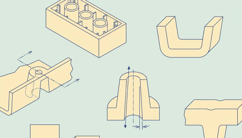
Hoe moeten wanddikte, ribben en penanten worden ontworpen?
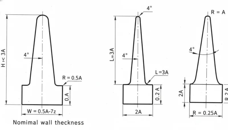
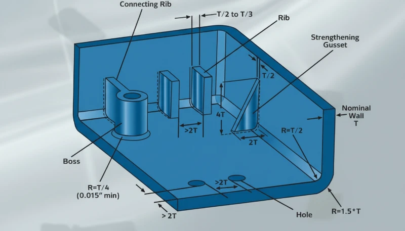
Wanddikte is de belangrijkste controle voor koeltijd, krimp en lokale spanning in een gespoten onderdeel. Het moet zo uniform zijn als de productfunctionaliteit toelaat, omdat dikte de koeltijd, krimp en lokale spanning bepaalt. Een nominale wanddikte is een doelwandwaarde die over het hele onderdeel wordt gebruikt, zodat stroming en koeling voorspelbaar blijven in plaats van sterk te veranderen van het ene naar het andere gebied.
Voor veel technische thermoplasten beginnen vroege concepten vaak met wanden van ongeveer 1,5 mm tot 3,0 mm, en worden aangepast nadat hars, stromingslengte, stijfheid en valtestbehoeften bekend zijn. Dunne secties kunnen bevriezen voordat de holte gevuld is, terwijl dikke secties warmte kunnen vasthouden en zichtbare zinkmarkeringen aan de cosmetische kant kunnen veroorzaken.
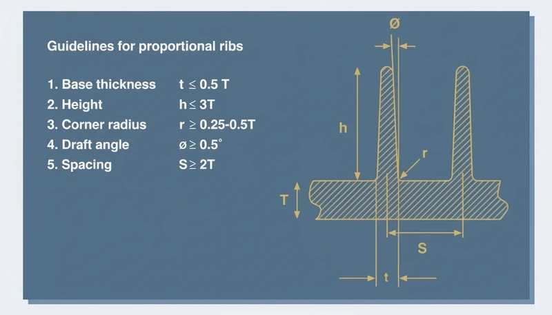
Ribben voegen stijfheid toe zonder het onderdeel in een dik blok te veranderen. Een veelvoorkomende rib-tot-wandverhouding3 doel is ongeveer 40% tot 60% van de aangrenzende wand, met ruime wortelstralen en voldoende tussenruimte voor staalsterkte. Als een rib te dik is, kan het buitenoppervlak indeuken; als hij te hoog en dun is, worden vullen en uitwerpen onstabiel.
Pennen vereisen dezelfde discipline. Een schroefpen moet verbonden zijn met ribben of steunribben, niet met een zware cilinder die op een dunne wand rust. De buitendiameter van de pen, de sterkte van de kernpen, de schroefinrijging en de uitwerprichting moeten samen worden beoordeeld, zodat het ontwerp geen kortschieten, brandsporen of gebroken kernpennen veroorzaakt.
In our factory DFM reviews, a wall transition above about 30% of the nearby wall is usually marked for discussion. We also review rib bases under magnification after first shots because a small sink mark on a visible housing can be harder to sell than a small tooling change.
Corners should be rounded instead of sharp. Internal radii improve flow and reduce stress concentration, while external radii keep wall thickness consistent around the corner. A sharp internal corner may look clean in CAD, but it makes the polymer turn abruptly and can leave a weak point under impact or vibration.
When the part must remain stiff, combine ribs, material selection, and local geometry. The best design is rarely the thickest design. It is the design that puts material where load paths need it while keeping the cooling profile even enough for repeatable molding.
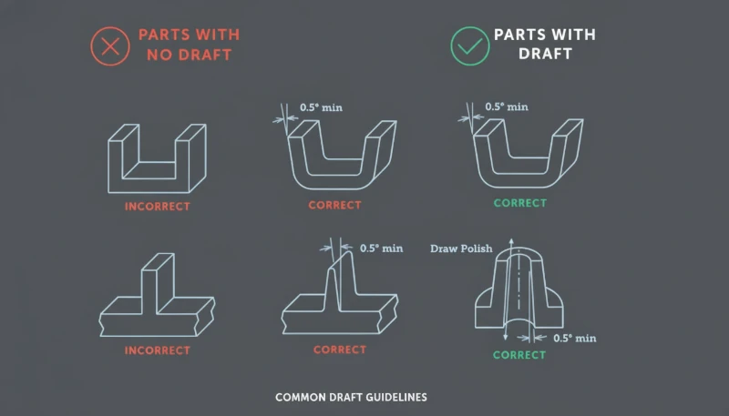
Hoe verminderen ontwerphelling, scheidingslijn en afsluitingen het gereedschapsrisico?
Draft angle is the clearance that helps a molded part release from the cavity or core. It reduces tooling risk by giving the molded part clearance as it leaves the cavity or core. Without enough draft angle, textured surfaces, deep ribs, and tall walls can rub against steel during ejection, causing drag marks, whitening, distortion, or stuck parts.
A typical early target is 1.0 degrees to 2.0 degrees per side for many smooth vertical faces, with more draft for texture or deep features. The final value depends on material shrinkage, surface finish, draw depth, tool polish, and whether the surface is cavity side or core side.
Parting line strategy should be chosen before the visual surface is locked. The parting line decides where flash may appear, where shutoff faces meet, and whether slides or lifters are needed. A beautiful product split can become expensive if it hides an unavoidable undercut or forces weak shutoff steel.
Shutoffs need enough angle and bearing area to survive repeated cycles. Very thin steel edges can chip, wear, or create flash after production starts. If a clip, window, vent, or snap requires a shutoff, the DFM review should check steel thickness, polishing access, and whether the feature can be redesigned for a safer mold action.
“Draft and parting line choices should be visible in the DFM review before the mold layout is approved.”Echt
This is true because these choices determine mold opening direction, slide count, shutoff wear, cosmetic marks, and ejection reliability. Late changes often require steel redesign.
“A zero-draft wall is acceptable when the CAD model has a smooth surface finish.”Vals
This is false because even a smooth surface can grip steel after shrinkage. Zero draft increases ejection force and can mark or deform the part during release.
Use mold-open direction as a design constraint, not as an afterthought. Mark core side, cavity side, slide pulls, lifter motion, and expected witness lines on the model. When our engineers review a housing, we often color-code those areas so the customer can see where function, appearance, and tooling cost are competing.
This is also where buyer and supplier communication matters. A supplier who only quotes the drawing may miss hidden tool risk; a supplier who explains draw direction, steel safety, and first-shot risk gives the buyer a better basis for decision-making. That is why design review should sit inside the commercial RFQ workflow, not after purchase order release.
Hoe moeten toleranties, materiaalkeuze en montagekenmerken in balans worden gebracht?
Tolerance balance is the process of matching dimensions, resin behavior, and assembly risk to real molding capability. Tolerance, material selection, and assembly features should be balanced by function, because every tight dimension adds process risk. GD&T is a drawing language that defines allowable variation in form, orientation, location, and runout so suppliers know which dimensions truly control assembly.
A molded plastic tolerance should consider resin shrinkage, tool temperature, moisture, filler content, part geometry, and measurement method. A 0.05 mm tolerance may be reasonable for a short steel feature in a machined part, but it can be unrealistic across a long molded span that cools unevenly.
Material choice changes the design rules. Glass-filled nylon may need stronger tool steel and more attention to fiber direction, while PC, ABS, PP, POM, PPSU, and PEEK each bring different shrinkage, stiffness, temperature resistance, and weld-line behavior. For early comparisons, review both product performance and molding stability.
Assembly features should be forgiving where possible. Snap fits need lead-in, strain control, and testable deflection limits. Screw bosses need core pin support and anti-splitting geometry. Living hinges, clips, seals, and ultrasonic welding ribs all require process-specific details, not generic wall additions.
| Design Area | Recommended Review | Factory Risk |
|---|---|---|
| Critical fit | Define datum and measurement method | Inspection dispute |
| Snap fit | Check strain and release direction | Cracking or weak retention |
| Baas | Check core pin and screw load | Short shot or split boss |
| Cosmetic face | Protect from gates and ejector marks | Visible defect |
For prototype-to-production programs, compare the molded design with the prototype process. A CNC prototype can hide molding risks because it does not need gate flow, shrinkage compensation, or ejection. The rapid prototyping injection molding explains when prototype tooling can reduce that gap before production steel.
Defect history should also feed the design review. If similar products had sink, flash, short shot, or warpage, use that evidence before the next mold is built. The common injection molding defects is useful when converting known failure modes into geometry checks.
Our team treats tolerance review as a risk-ranking exercise. We prefer to hold tight tolerance only where the product function needs it, then open noncritical surfaces to protect cycle stability, inspection speed, and long-term production yield.
Before approving steel, convert those tolerance choices into inspection notes. Define the datum surfaces, the fixture concept, the measurement temperature, and the sampling rule. This prevents a drawing from asking for precision that no one can measure consistently during production.
Welke ontwerpbeoordelingsworkflow moeten kopers vereisen vóór gereedschapsbouw?
A design review workflow is a staged DFM gate before tooling begins. It checks product function, resin choice, mold action, gate location, cooling, ejection, tolerance, and inspection. This workflow turns design principles into decisions that can be verified instead of opinions exchanged by email.
The first gate is a geometry review. Confirm wall map, rib map, boss layout, corner radii, draft, parting line, and undercuts. The second gate is a tooling review. Confirm cavity count, slide and lifter actions, gate type, cooling channel access, venting, steel safety, and expected maintenance points.
The third gate is a production review. Confirm resin drying, expected cycle time, cosmetic acceptance criteria, inspection fixtures, packaging loads, and change-control rules. A mold that passes sample approval but lacks a production plan can still fail when order volume increases.
Keep the review evidence append-only. Save marked screenshots, DFM comments, customer approvals, first-shot reports, and mold-change records. When a later defect appears, this history shows whether the issue came from design, tooling, material, process setup, or an undocumented change.
The best outcome is not a longer checklist. It is a shorter path from product requirement to stable production. When the design file, mold plan, and inspection criteria are aligned, the supplier can quote more accurately, the buyer can compare proposals more fairly, and the first production run has fewer avoidable surprises.
For rank-recovery content, this workflow also matters to search quality. Readers need a page that answers design questions directly, shows production evidence, and gives them a practical review sequence they can use on the next project. That combination is stronger than a generic list of plastic design tips.
It also gives the sales team a clearer inquiry path, because a buyer can attach drawings, highlight the risky features, and ask for a focused DFM response instead of sending only a price request.
Veelgestelde vragen
Wat is de belangrijkste ontwerpregel voor spuitgietproducten?
De belangrijkste regel is om het onderdeel te ontwerpen rond consistente vulling, koeling en uitwerping in plaats van alleen rond de uiteindelijke productvorm. Uniforme wanddikte, vloeiende overgangen, realistische toleranties en voldoende ontluchtingshoek voorkomen veelvoorkomende gietfouten. Wanneer die basisprincipes worden genegeerd, kan de matrijsmaker nog steeds monsters produceren, maar de productie kan lijden onder zinkmerken, vervorming, vastzittende onderdelen, uitvloeiing en instabiele afmetingen. Dit verandert DFM in een gedeelde checklist voor zowel koper als leverancier en voorkomt late geschillen over wat de matrijs moest oplossen.
Hoeveel ontluchtingshoek moet een kunststofonderdeel hebben?
Een nuttig vroeg doel is vaak 1,0 graden tot 2,0 graden per zijde op gladde verticale wanden, maar de uiteindelijke ontluchting hangt af van materiaal, textuur, trekkracht, krimp en cosmetische vereisten. Diepe ribben, getextureerde oppervlakken en met glasvezel versterkte materialen hebben meestal een conservatievere beoordeling nodig. De juiste vraag is niet alleen hoeveel ontluchting zichtbaar is in CAD, maar of het onderdeel schoon kan worden vrijgegeven voor de verwachte productievolume zonder sleepsporen, verbleking, vervorming of overmatige uitwerpkracht. Textuurdiepte en polijsttoegang moeten ook in die beslissing worden meegenomen.
Waarom veroorzaken ribben zinkmerken bij spuitgieten?
Ribben veroorzaken zinkmerken wanneer de ribbasis een lokaal dikke sectie creëert die langzamer afkoelt dan de omliggende wand. Terwijl dat zware gebied krimpt, kan het buitenste cosmetische oppervlak naar binnen trekken en een zichtbare indeuking vertonen. De gebruikelijke oplossing is om de ribdikte te verminderen, royale stralen toe te voegen, één zware rib in meerdere lichtere ribben te splitsen of de functie weg te halen van een kritisch uiterlijk oppervlak. De rib moet de stijfheid verbeteren zonder zich te gedragen als een verborgen blok kunststof dat de koeling vertraagt.
Moet een gegoten kunststofonderdeel overal zeer strakke toleranties gebruiken?
Nee. Strakke toleranties moeten worden gereserveerd voor functionele interfaces zoals afdichtingsvlakken, klikverbindingen, tandwieluitlijning, connectorlocaties of assemblage-referentiepunten. Niet-kritieke oppervlakken moeten ruimere toleranties gebruiken zodat het spuitgietproces stabiel kan blijven. Overal strakke toleranties toepassen verhoogt de inspectiekosten, het risico op afval, de matrijsaanpassingstijd en de verwarring bij leveranciers zonder de uiteindelijke productfunctie te verbeteren. Een betere tekening scheidt kritische functiedimensies van cosmetische of spelingdimensies en maakt de meetverantwoordelijkheid duidelijk. Dit helpt de leverancier ook eerlijk inspectie-inrichtingen, steekproeffrequentie en verwachte procescapaciteit te quoteren.
Wanneer moet DFM-beoordeling plaatsvinden in een nieuw spuitgietproject?
DFM-beoordeling moet plaatsvinden voordat de matrijsofferte wordt afgerond en opnieuw voordat het matrijzenstaal wordt gesneden. De eerste beoordeling identificeert geometrie- en procesrisico's terwijl ontwerpwijzigingen nog goedkoop zijn. De tweede beoordeling bevestigt de overeengekomen matrijsindeling, poortlocatie, scheidingslijn, uitwerpplan en inspectievereisten. Wachten tot de eerste shots verandert veel eenvoudige CAD-wijzigingen in dure matrijswijzigingen. Een gedocumenteerde beoordeling geeft de koper ook beter bewijs bij het vergelijken van leveranciers en het goedkeuren van de matrijslancering. Het moet worden opgeslagen met tekeningen, matrijsindeling en goedkeuringsrecords.
-
draft angle: De ontwerphelling is een kleine tapsheid die wordt toegepast op verticale vlakken, zodat een gegoten onderdeel met minder wrijving uit de holte of kern kan worden losgemaakt. ↩
-
nominale wanddikte: Nominale wanddikte is een doelwandwaarde die wordt gebruikt als basislijn voor de beoordeling van koeling, vulling, stijfheid en krimp in een gegoten kunststofonderdeel. ↩
-
rib-tot-wandverhouding: Rib-tot-wandverhouding verwijst naar de relatie tussen de dikte van de ribbasis en de aangrenzende nominale wand, zodat de stijfheid kan toenemen zonder overmatige zink. ↩


