 コンテンツへスキップ

Injection molded product design is the work of turning a useful product idea into geometry that can fill, cool, eject, assemble, and repeat in production. A part can look simple in CAD yet still create sink marks, drag scratches, trapped gas, flash, broken ejector pins, or mold rework if the design ignores tooling and process limits.
This guide rebuilds the design principles for injection molding products around production reality. It focuses on wall thickness, ribs, 抜き勾配1, shutoffs, tolerance, material behavior, and review discipline, because those choices decide whether a tool runs stable after steel is cut.
Use it before design freeze, not after first shots. When our factory reviews a new plastic part, we try to find the mold risk while it is still a CAD decision, because a 0.3 mm geometry change before tooling is much cheaper than a welded insert or an emergency steel modification later.
- Design for molding starts with uniform material flow, predictable cooling, and safe ejection.
- Wall thickness, ribs, bosses, and corners should be sized as one connected system.
- Draft angle and parting strategy must be reviewed before tooling because they control release and flash risk.
- Tolerance should be assigned by function and process capability, not copied from machined-metal drawings.
- A short DFM review before mold build prevents many late-stage defects and cost surprises.
What are the core design principles for injection molding products?
The core design principles for injection molding products are the main categories or options explained in this section. The core design principles for injection molding products are uniform wall thickness, balanced flow length, controlled cooling, reliable ejection, realistic tolerance, and tool-safe geometry. These principles work together because plastic shrinks while it cools and because the mold must release the finished part without dragging or deformation.
Start by treating the part as a flow-and-cooling problem. A gate can only push molten material so far before pressure, shear, and cooling change the filling pattern. If one zone is much thicker than the rest, that zone stays hot longer, shrinks later, and often creates sink, voids, or local warpage.
The safest early review connects product function to manufacturing limits. A useful product spec says which surfaces are cosmetic, which dimensions control assembly, which areas can accept ejector marks, and which loads the part must survive. That information lets the designer and mold maker trade geometry, gate location, and material before the tool layout is fixed.
For a broader process foundation, use ZetarMold’s 射出成形プロセスガイド. For tooling decisions such as parting line, slides, lifters, cooling, and steel-safe changes, connect the review to the injection mold guide. If the buyer is selecting a factory, the supplier sourcing guide helps turn those checks into sourcing questions.
“A molded part should be designed around melt flow, cooling, and ejection before cosmetic styling is locked.”真
This is true because the mold cannot correct every geometry problem after steel cutting. Styling, ribs, bosses, clips, and tolerance stacks all influence pressure loss, shrinkage, draft, and release force.
“Any plastic part can keep the same geometry as a CNC machined part if the material is strong enough.”偽
This is false because molding adds shrinkage, cooling gradients, ejector loads, parting constraints, and gate vestige. Material strength does not remove the need for molding-specific geometry.
| Principle | What to Check | Risk if Ignored |
|---|---|---|
| Wall control | Keep transitions gradual and avoid isolated mass | Sink, voids, warpage |
| Mold release | Add draft and avoid trapped undercuts | Drag marks, stuck parts |
| Functional tolerance | Limit tight tolerances to critical interfaces | High scrap and mold rework |
| Review timing | Run DFM before tool build | Late design changes |
A practical DFM pass should ask whether the nominal wall thickness2 is consistent enough for the chosen resin, whether the longest flow path can fill without overpacking, and whether the cosmetic face can be protected from gates and ejector marks. Our engineers usually flag high-risk zones first, then rank each fix by cost, lead time, and effect on product function.
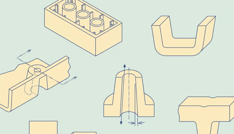
How should wall thickness, ribs, and bosses be designed?
Wall thickness is the main control for cooling time, shrinkage, and local stress in a molded part. It should be as uniform as the product function allows, because thickness controls cooling time, shrinkage, and local stress. A nominal wall thickness is a target wall value used across the part so flow and cooling remain predictable instead of changing sharply from one region to another.
For many engineering thermoplastics, early concepts often start near 1.5 mm to 3.0 mm walls, then move after resin, flow length, stiffness, and drop-test needs are known. Thin sections may freeze before the cavity fills, while thick sections can hold heat and create visible sink on the cosmetic side.
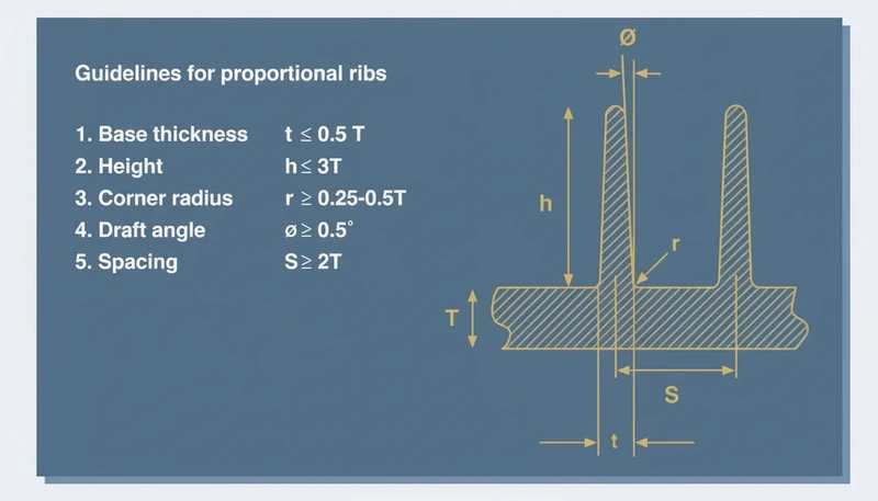
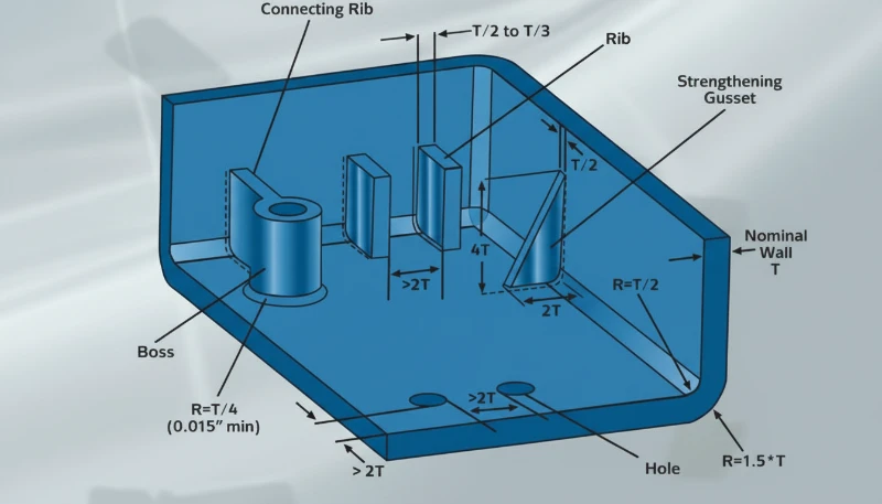
Ribs add stiffness without turning the part into one thick block. A common rib-to-wall ratio3 target is about 40% to 60% of the adjacent wall, with generous root radii and enough spacing for steel strength. If a rib is too thick, the outer surface can sink; if it is too tall and thin, filling and ejection become unstable.
Bosses need the same discipline. A screw boss should be connected with ribs or gussets, not a heavy cylinder sitting on a thin wall. The boss outside diameter, core pin strength, screw engagement, and ejection direction should be reviewed together so the design does not create short shots, burn marks, or broken core pins.
In our factory DFM reviews, a wall transition above about 30% of the nearby wall is usually marked for discussion. We also review rib bases under magnification after first shots because a small sink mark on a visible housing can be harder to sell than a small tooling change.
Corners should be rounded instead of sharp. Internal radii improve flow and reduce stress concentration, while external radii keep wall thickness consistent around the corner. A sharp internal corner may look clean in CAD, but it makes the polymer turn abruptly and can leave a weak point under impact or vibration.
When the part must remain stiff, combine ribs, material selection, and local geometry. The best design is rarely the thickest design. It is the design that puts material where load paths need it while keeping the cooling profile even enough for repeatable molding.
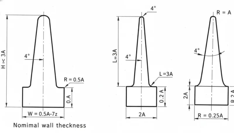
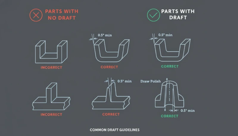
How do draft angle, parting line, and shutoffs reduce tooling risk?
Draft angle is the clearance that helps a molded part release from the cavity or core. It reduces tooling risk by giving the molded part clearance as it leaves the cavity or core. Without enough draft angle, textured surfaces, deep ribs, and tall walls can rub against steel during ejection, causing drag marks, whitening, distortion, or stuck parts.
A typical early target is 1.0 degrees to 2.0 degrees per side for many smooth vertical faces, with more draft for texture or deep features. The final value depends on material shrinkage, surface finish, draw depth, tool polish, and whether the surface is cavity side or core side.
Parting line strategy should be chosen before the visual surface is locked. The parting line decides where flash may appear, where shutoff faces meet, and whether slides or lifters are needed. A beautiful product split can become expensive if it hides an unavoidable undercut or forces weak shutoff steel.
Shutoffs need enough angle and bearing area to survive repeated cycles. Very thin steel edges can chip, wear, or create flash after production starts. If a clip, window, vent, or snap requires a shutoff, the DFM review should check steel thickness, polishing access, and whether the feature can be redesigned for a safer mold action.
“Draft and parting line choices should be visible in the DFM review before the mold layout is approved.”真
This is true because these choices determine mold opening direction, slide count, shutoff wear, cosmetic marks, and ejection reliability. Late changes often require steel redesign.
“A zero-draft wall is acceptable when the CAD model has a smooth surface finish.”偽
This is false because even a smooth surface can grip steel after shrinkage. Zero draft increases ejection force and can mark or deform the part during release.
Use mold-open direction as a design constraint, not as an afterthought. Mark core side, cavity side, slide pulls, lifter motion, and expected witness lines on the model. When our engineers review a housing, we often color-code those areas so the customer can see where function, appearance, and tooling cost are competing.
This is also where buyer and supplier communication matters. A supplier who only quotes the drawing may miss hidden tool risk; a supplier who explains draw direction, steel safety, and first-shot risk gives the buyer a better basis for decision-making. That is why design review should sit inside the commercial RFQ workflow, not after purchase order release.
How should tolerances, material selection, and assembly features be balanced?
Tolerance balance is the process of matching dimensions, resin behavior, and assembly risk to real molding capability. Tolerance, material selection, and assembly features should be balanced by function, because every tight dimension adds process risk. GD&T is a drawing language that defines allowable variation in form, orientation, location, and runout so suppliers know which dimensions truly control assembly.
A molded plastic tolerance should consider resin shrinkage, tool temperature, moisture, filler content, part geometry, and measurement method. A 0.05 mm tolerance may be reasonable for a short steel feature in a machined part, but it can be unrealistic across a long molded span that cools unevenly.
Material choice changes the design rules. Glass-filled nylon may need stronger tool steel and more attention to fiber direction, while PC, ABS, PP, POM, PPSU, and PEEK each bring different shrinkage, stiffness, temperature resistance, and weld-line behavior. For early comparisons, review both product performance and molding stability.
Assembly features should be forgiving where possible. Snap fits need lead-in, strain control, and testable deflection limits. Screw bosses need core pin support and anti-splitting geometry. Living hinges, clips, seals, and ultrasonic welding ribs all require process-specific details, not generic wall additions.
| Design Area | Recommended Review | Factory Risk |
|---|---|---|
| Critical fit | Define datum and measurement method | Inspection dispute |
| Snap fit | Check strain and release direction | Cracking or weak retention |
| ボス | Check core pin and screw load | Short shot or split boss |
| Cosmetic face | Protect from gates and ejector marks | Visible defect |
For prototype-to-production programs, compare the molded design with the prototype process. A CNC prototype can hide molding risks because it does not need gate flow, shrinkage compensation, or ejection. The rapid prototyping injection molding explains when prototype tooling can reduce that gap before production steel.
Defect history should also feed the design review. If similar products had sink, flash, short shot, or warpage, use that evidence before the next mold is built. The common injection molding defects is useful when converting known failure modes into geometry checks.
Our team treats tolerance review as a risk-ranking exercise. We prefer to hold tight tolerance only where the product function needs it, then open noncritical surfaces to protect cycle stability, inspection speed, and long-term production yield.
Before approving steel, convert those tolerance choices into inspection notes. Define the datum surfaces, the fixture concept, the measurement temperature, and the sampling rule. This prevents a drawing from asking for precision that no one can measure consistently during production.
What design review workflow should buyers require before tooling?
A design review workflow is a staged DFM gate before tooling begins. It checks product function, resin choice, mold action, gate location, cooling, ejection, tolerance, and inspection. This workflow turns design principles into decisions that can be verified instead of opinions exchanged by email.
The first gate is a geometry review. Confirm wall map, rib map, boss layout, corner radii, draft, parting line, and undercuts. The second gate is a tooling review. Confirm cavity count, slide and lifter actions, gate type, cooling channel access, venting, steel safety, and expected maintenance points.
The third gate is a production review. Confirm resin drying, expected cycle time, cosmetic acceptance criteria, inspection fixtures, packaging loads, and change-control rules. A mold that passes sample approval but lacks a production plan can still fail when order volume increases.
Keep the review evidence append-only. Save marked screenshots, DFM comments, customer approvals, first-shot reports, and mold-change records. When a later defect appears, this history shows whether the issue came from design, tooling, material, process setup, or an undocumented change.
The best outcome is not a longer checklist. It is a shorter path from product requirement to stable production. When the design file, mold plan, and inspection criteria are aligned, the supplier can quote more accurately, the buyer can compare proposals more fairly, and the first production run has fewer avoidable surprises.
For rank-recovery content, this workflow also matters to search quality. Readers need a page that answers design questions directly, shows production evidence, and gives them a practical review sequence they can use on the next project. That combination is stronger than a generic list of plastic design tips.
It also gives the sales team a clearer inquiry path, because a buyer can attach drawings, highlight the risky features, and ask for a focused DFM response instead of sending only a price request.
よくある質問
What is the most important design rule for injection molded products?
The most important rule is to design the part around consistent filling, cooling, and ejection instead of only around the final product shape. Uniform wall thickness, smooth transitions, realistic tolerance, and sufficient draft prevent many common molding failures. When those basics are ignored, the mold maker may still produce samples, but production can suffer from sink marks, warpage, stuck parts, flash, and unstable dimensions. This turns DFM into a shared checklist for both buyer and supplier and prevents late disputes about what the tool was expected to solve.
プラスチック部品にはどの程度の抜き勾配が必要ですか?
有用な初期目標は、平滑な垂直壁に対して通常片側1.0度から2.0度ですが、最終的な抜き勾配は材料、テクスチャ、引き出し深さ、収縮、外観要件に依存します。深いリブ、テクスチャ面、ガラス充填材料は通常、より保守的なレビューが必要です。正しい質問は、CADでどの程度の抜き勾配が見えるかだけでなく、部品が期待される生産量において、引き跡、白化、変形、過剰なエジェクター力なしに、きれいに離脱できるかどうかです。テクスチャ深さと研磨アクセスもその決定に含めるべきです。
射出成形において、リブがシンクマークを引き起こす理由は何ですか?
リブは、リブ基部が局所的に厚い断面を作り、周囲の壁よりも冷却が遅くなることでシンクマークを引き起こします。その厚い領域が収縮すると、外側の外観面が内側に引き込まれ、目に見える凹みが現れます。通常の修正方法は、リブ厚を減らす、十分な半径を追加する、1つの厚いリブをいくつかの細いリブに分割する、または重要な外観面から特徴を遠ざけることです。リブは、剛性を向上させるべきですが、冷却を遅らせる隠れたプラスチックブロックのように振る舞うべきではありません。
成形プラスチック部品は、どこにも非常に厳しい公差を使用するべきですか?
いいえ。厳しい公差は、シール面、スナップフィット、歯車位置合わせ、コネクタ位置、組み合わせ基準などの機能インターフェースに限定されるべきです。非重要な表面は広い公差を使用し、成形工程を安定させます。厳しい公差をどこにも適用すると、検査コスト、スクラップリスク、金型調整時間、サプライヤーの混乱を増加させ、最終製品機能を改善しません。より良い図面は、機能上重要な寸法と外観またはクリアランス寸法を分離し、測定責任を明確にします。これはまた、サプライヤーが検査治具、サンプリング頻度、期待される工程能力を正直に見積るのに役立ちます。
新しい射出成形プロジェクトにおいて、DFMレビューはいつ実施されるべきですか?
DFMレビューは、金型見積が確定する前と、工具鋼材が切削される前の2回実施する必要があります。最初のレビューでは、設計変更がまだ低コストな段階で形状と工程リスクを発見します。第2回のレビューでは、合意された金型レイアウト、ゲート位置、パーティングライン、エジェクション計画、検査要件を確認します。初回試作まで待つと、多くの単純なCAD変更が高額な金型修正に変わります。文書化されたレビューは、買い手がサプライヤーを比較し、工具立ち上げを承認する際に、より良い証拠を提供します。これは、図面、金型レイアウト、承認記録とともに保管されるべきです。


