 Skip to content

La conception de produits en injection plastique consiste à transformer une idée de produit utile en une géométrie qui peut être remplie, refroidie, éjectée, assemblée et répétée en production. Une pièce peut sembler simple en CAO, mais générer encore des retassures, des rayures de traînée, du gaz piégé, des bavures, des éjecteurs cassés ou une retouche de moule si la conception ignore les limites de l'outillage et du procédé.
Ce guide reconstitue les principes de conception pour les produits moulés par injection autour de la réalité de production. Il se concentre sur l'épaisseur de paroi, les nervures, angle de dépouille1, les obturations, la tolérance, le comportement de la matière et la discipline de revue, car ces choix déterminent si un outillage fonctionne de manière stable après l'usinage de l'acier.
Utilisez-le avant la finalisation du design, pas après les premiers tirages. Lorsque notre usine examine une nouvelle pièce plastique, nous essayons de identifier le risque de moule lorsqu'il est encore une décision CAO, car un changement géométrique de 0,3 mm avant l'outillage est beaucoup moins cher qu'une insertion soudée ou une modification urgente du métal ultérieure.
- La conception pour le moulage commence avec un flux de matériau uniforme, un refroidissement prévisible et une éjection sûre.
- L'épaisseur des parois, les nervures, les bossages et les angles doivent être dimensionés comme un système connecté.
- L'angle de dépouille et la stratégie de séparation doivent être revus avant la fabrication de l'outillage car ils contrôlent le démoulage et le risque de bavure.
- La tolérance doit être assignée selon la fonction et la capacité du processus, pas copiée des dessins de métal usiné.
- Une courte revue DFM avant la construction du moule prévient beaucoup de défauts de dernière étape et de surprises de coût.
Quels sont les principes de conception fondamentaux pour les produits en injection plastique ?
Les principes de conception fondamentaux pour les produits en injection plastique sont les principales catégories ou options expliquées dans cette section. Ces principes sont l'épaisseur de paroi uniforme, la longueur d'écoulement équilibrée, le refroidissement maîtrisé, l'éjection fiable, la tolérance réaliste et la géométrie sûre pour l'outillage. Ces principes agissent ensemble car le plastique rétrécit en refroidissant et le moule doit libérer la pièce finie sans traînée ni déformation.
Commencez par traiter la pièce comme un problème d'écoulement et de refroidissement. Une porte d'injection ne peut pousser la matière fondue que jusqu'à une certaine distance avant que la pression, le cisaillement et le refroidissement ne modifient le motif de remplissage. Si une zone est beaucoup plus épaisse que le reste, cette zone reste chaude plus longtemps, rétrécit plus tard et crée souvent des retassures, des vides ou un voilage local.
L'examen précoce le plus sûr relie la fonction du produit aux limites de fabrication. Une spécification produit utile indique quelles surfaces sont cosmétiques, quelles dimensions contrôlent l'assemblage, quelles zones peuvent accepter les marques d'éjecteurs, et quelles charges la pièce doit supporter. Ces informations permettent au concepteur et au mouliste d'échanger sur la géométrie, l'emplacement de l'attaque et le matériau avant que la disposition de l'outillage ne soit fixée.
Pour une base de procédé plus large, utilisez guide de processus de moulage par injection. Pour les décisions d'outillage telles que la ligne de joint, les coulisseaux, les éjecteurs latéraux, le refroidissement et les modifications sûres pour l'acier, reliez la revue au injection mold guide. Si l'acheteur sélectionne une usine, le supplier sourcing guide aide à transformer ces vérifications en questions d'approvisionnement.
« Une pièce moulée doit être conçue autour de l'écoulement de la matière fondue, du refroidissement et de l'éjection avant que le style esthétique ne soit figé. »Vrai
C'est vrai car le moule ne peut corriger tous les problèmes géométriques après la coupe du métal. Le style, les nervures, les bossages, les clips et les cumuls de tolérance influencent tous la perte de pression, le retrait, la dépouille et la force de démoulage.
« Toute pièce plastique peut garder la même géométrie qu'une pièce usinée CNC si le matériau est suffisamment résistant. »Faux
Ceci est faux car le moulage ajoute le retrait, les gradients de refroidissement, les charges d'éjection, les contraintes de joint et les vestiges d'attaque. La résistance du matériau n'élimine pas le besoin d'une géométrie spécifique au moulage.
| Principe | What to Check | Risque si ignoré |
|---|---|---|
| Maîtrise de la paroi | Garder les transitions graduelles et éviter les masses isolées | Enfoncement, cavités, déformation |
| Démoulage | Ajouter une dépouille et éviter les contre-dépouilles bloquées | Marques de traînée, pièces coincées |
| Tolérance fonctionnelle | Limiter les tolérances serrées aux interfaces critiques | Fort taux de rebut et retouche de moule |
| Calendrier de revue | Exécuter une DFM avant la construction de l'outillage | Modifications tardives de la conception |
Une passe DFM pratique devrait demander si le épaisseur nominale de paroi2 est suffisamment cohérent pour la résine choisie, si le chemin d'écoulement le plus long peut se remplir sans surcompaction, et si la face cosmétique peut être protégée des attaques et des marques d'éjecteurs. Nos ingénieurs signalent généralement d'abord les zones à haut risque, puis classent chaque correction par coût, délai et impact sur la fonction du produit.
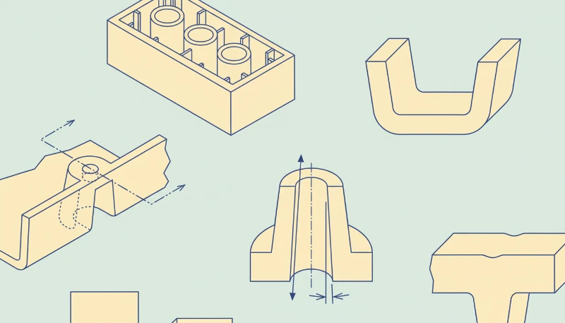
Comment concevoir l'épaisseur de paroi, les nervures et les bossages ?
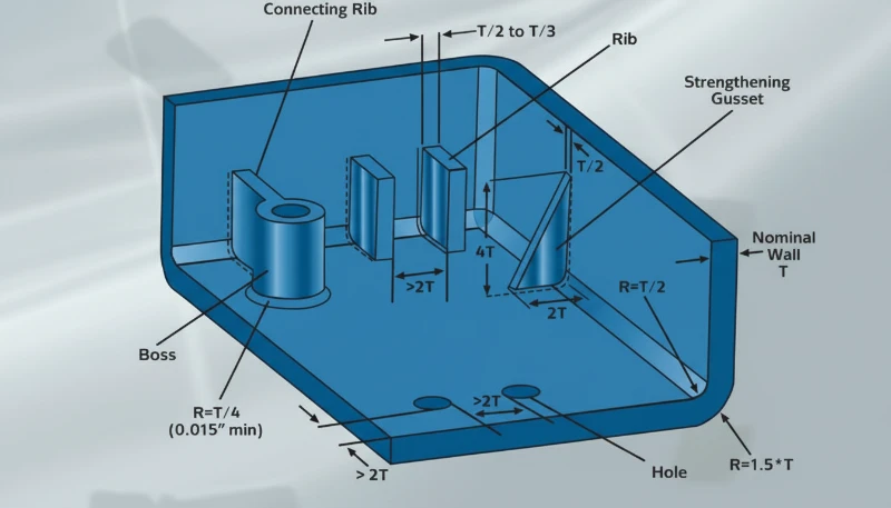
L'épaisseur de paroi est le principal paramètre de contrôle du temps de refroidissement, du retrait et des contraintes locales dans une pièce moulée. Elle doit être aussi uniforme que la fonction du produit le permet, car l'épaisseur contrôle le temps de refroidissement, le retrait et les contraintes locales. Une épaisseur de paroi nominale est une valeur cible utilisée sur toute la pièce afin que l'écoulement et le refroidissement restent prévisibles au lieu de changer brutalement d'une région à l'autre.
Pour de nombreux thermoplastiques techniques, les premiers concepts commencent souvent avec des parois de 1,5 mm à 3,0 mm, puis sont ajustés après que les besoins en résine, longueur de flux, rigidité et tests de chute sont connus. Les sections fines peuvent figer avant que la cavité soit remplie, tandis que les sections épaisse peuvent retenir la chaleur et créer un enfoncement visible sur la face esthétique.
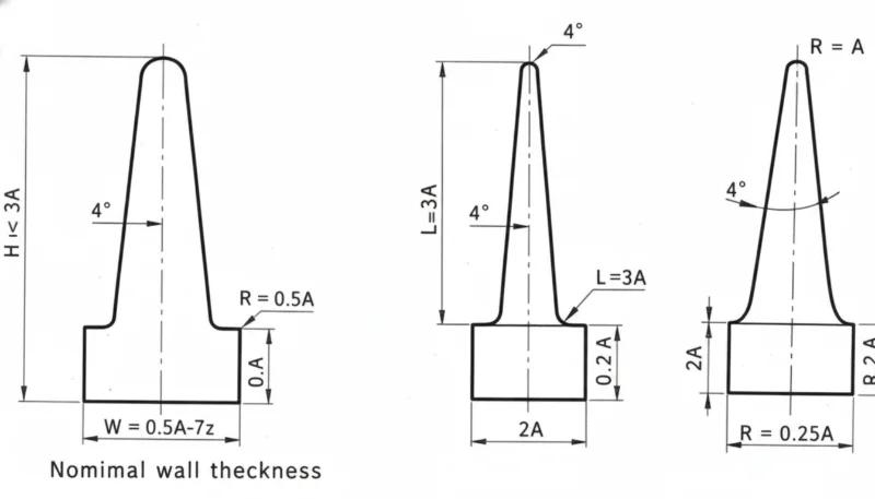
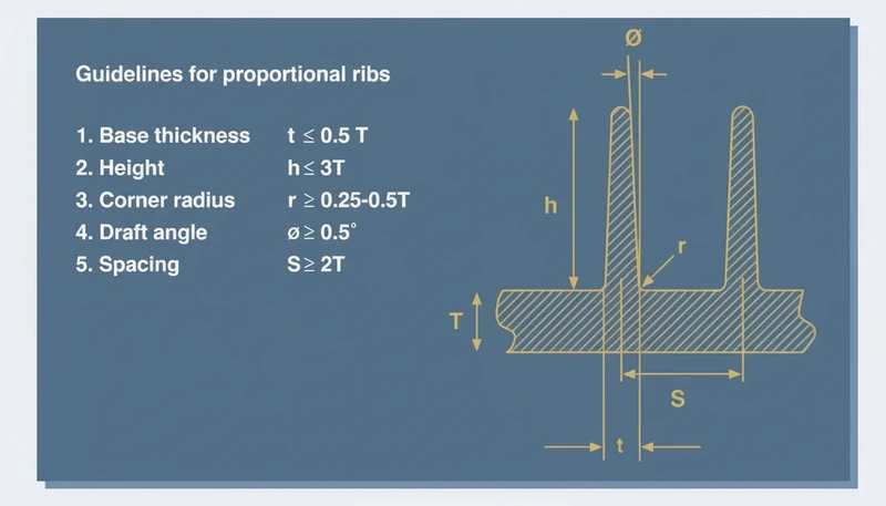
Les nervures ajoutent de la rigidité sans transformer la pièce en un bloc épais. Une pratique courante ratio nervure/paroi3 L'objectif est environ 40% à 60% de la paroi adjacente, avec des rayons de racine généreux et un espacement suffisant pour la résistance du métal. Si une nervure est trop épaisse, la surface externe peut s'enfoncer ; si elle est trop haute et fine, le remplissage et l'éjection deviennent instables.
Les bossages nécessitent la même discipline. Un bossage de vis doit être relié par des nervures ou des goussets, et non par un cylindre massif reposant sur une paroi fine. Le diamètre extérieur du bossage, la résistance de l'âme, l'engagement de la vis et la direction d'éjection doivent être revus ensemble afin que la conception ne crée pas de manques de matière, de marques de brûlure ou d'âmes cassées.
In our factory DFM reviews, a wall transition above about 30% of the nearby wall is usually marked for discussion. We also review rib bases under magnification after first shots because a small sink mark on a visible housing can be harder to sell than a small tooling change.
Corners should be rounded instead of sharp. Internal radii improve flow and reduce stress concentration, while external radii keep wall thickness consistent around the corner. A sharp internal corner may look clean in CAD, but it makes the polymer turn abruptly and can leave a weak point under impact or vibration.
When the part must remain stiff, combine ribs, material selection, and local geometry. The best design is rarely the thickest design. It is the design that puts material where load paths need it while keeping the cooling profile even enough for repeatable molding.
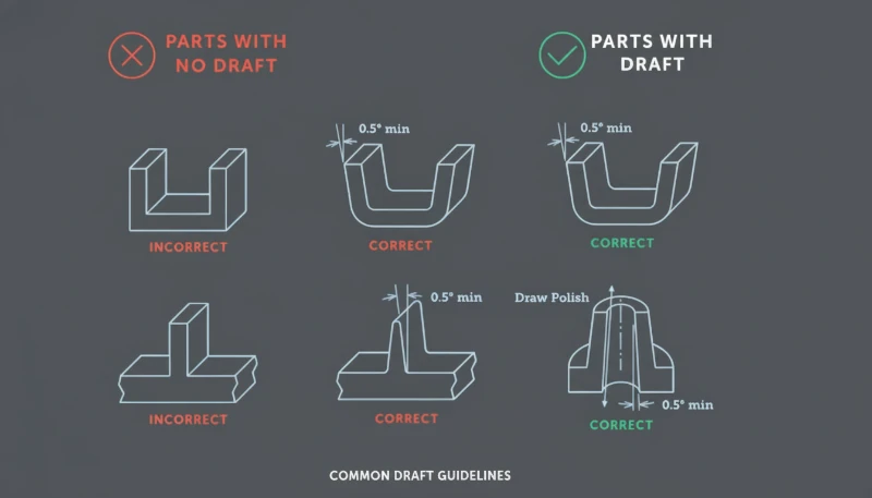
Comment l'angle de dépouille, la ligne de séparation et les fermetures réduisent le risque d'outillage ?
Draft angle is the clearance that helps a molded part release from the cavity or core. It reduces tooling risk by giving the molded part clearance as it leaves the cavity or core. Without enough draft angle, textured surfaces, deep ribs, and tall walls can rub against steel during ejection, causing drag marks, whitening, distortion, or stuck parts.
A typical early target is 1.0 degrees to 2.0 degrees per side for many smooth vertical faces, with more draft for texture or deep features. The final value depends on material shrinkage, surface finish, draw depth, tool polish, and whether the surface is cavity side or core side.
Parting line strategy should be chosen before the visual surface is locked. The parting line decides where flash may appear, where shutoff faces meet, and whether slides or lifters are needed. A beautiful product split can become expensive if it hides an unavoidable undercut or forces weak shutoff steel.
Shutoffs need enough angle and bearing area to survive repeated cycles. Very thin steel edges can chip, wear, or create flash after production starts. If a clip, window, vent, or snap requires a shutoff, the DFM review should check steel thickness, polishing access, and whether the feature can be redesigned for a safer mold action.
“Draft and parting line choices should be visible in the DFM review before the mold layout is approved.”Vrai
This is true because these choices determine mold opening direction, slide count, shutoff wear, cosmetic marks, and ejection reliability. Late changes often require steel redesign.
“A zero-draft wall is acceptable when the CAD model has a smooth surface finish.”Faux
This is false because even a smooth surface can grip steel after shrinkage. Zero draft increases ejection force and can mark or deform the part during release.
Use mold-open direction as a design constraint, not as an afterthought. Mark core side, cavity side, slide pulls, lifter motion, and expected witness lines on the model. When our engineers review a housing, we often color-code those areas so the customer can see where function, appearance, and tooling cost are competing.
This is also where buyer and supplier communication matters. A supplier who only quotes the drawing may miss hidden tool risk; a supplier who explains draw direction, steel safety, and first-shot risk gives the buyer a better basis for decision-making. That is why design review should sit inside the commercial RFQ workflow, not after purchase order release.
Comment équilibrer les tolérances, le choix des matériaux et les caractéristiques d'assemblage ?
Tolerance balance is the process of matching dimensions, resin behavior, and assembly risk to real molding capability. Tolerance, material selection, and assembly features should be balanced by function, because every tight dimension adds process risk. GD&T is a drawing language that defines allowable variation in form, orientation, location, and runout so suppliers know which dimensions truly control assembly.
A molded plastic tolerance should consider resin shrinkage, tool temperature, moisture, filler content, part geometry, and measurement method. A 0.05 mm tolerance may be reasonable for a short steel feature in a machined part, but it can be unrealistic across a long molded span that cools unevenly.
Material choice changes the design rules. Glass-filled nylon may need stronger tool steel and more attention to fiber direction, while PC, ABS, PP, POM, PPSU, and PEEK each bring different shrinkage, stiffness, temperature resistance, and weld-line behavior. For early comparisons, review both product performance and molding stability.
Assembly features should be forgiving where possible. Snap fits need lead-in, strain control, and testable deflection limits. Screw bosses need core pin support and anti-splitting geometry. Living hinges, clips, seals, and ultrasonic welding ribs all require process-specific details, not generic wall additions.
| Design Area | Recommended Review | Factory Risk |
|---|---|---|
| Critical fit | Define datum and measurement method | Inspection dispute |
| Snap fit | Check strain and release direction | Cracking or weak retention |
| Patron | Check core pin and screw load | Short shot or split boss |
| Cosmetic face | Protect from gates and ejector marks | Visible defect |
For prototype-to-production programs, compare the molded design with the prototype process. A CNC prototype can hide molding risks because it does not need gate flow, shrinkage compensation, or ejection. The rapid prototyping injection molding explains when prototype tooling can reduce that gap before production steel.
Defect history should also feed the design review. If similar products had sink, flash, short shot, or warpage, use that evidence before the next mold is built. The common injection molding defects is useful when converting known failure modes into geometry checks.
Our team treats tolerance review as a risk-ranking exercise. We prefer to hold tight tolerance only where the product function needs it, then open noncritical surfaces to protect cycle stability, inspection speed, and long-term production yield.
Before approving steel, convert those tolerance choices into inspection notes. Define the datum surfaces, the fixture concept, the measurement temperature, and the sampling rule. This prevents a drawing from asking for precision that no one can measure consistently during production.
Quel workflow de revue de conception les acheteurs doivent exiger avant l'outillage ?
A design review workflow is a staged DFM gate before tooling begins. It checks product function, resin choice, mold action, gate location, cooling, ejection, tolerance, and inspection. This workflow turns design principles into decisions that can be verified instead of opinions exchanged by email.
The first gate is a geometry review. Confirm wall map, rib map, boss layout, corner radii, draft, parting line, and undercuts. The second gate is a tooling review. Confirm cavity count, slide and lifter actions, gate type, cooling channel access, venting, steel safety, and expected maintenance points.
The third gate is a production review. Confirm resin drying, expected cycle time, cosmetic acceptance criteria, inspection fixtures, packaging loads, and change-control rules. A mold that passes sample approval but lacks a production plan can still fail when order volume increases.
Keep the review evidence append-only. Save marked screenshots, DFM comments, customer approvals, first-shot reports, and mold-change records. When a later defect appears, this history shows whether the issue came from design, tooling, material, process setup, or an undocumented change.
The best outcome is not a longer checklist. It is a shorter path from product requirement to stable production. When the design file, mold plan, and inspection criteria are aligned, the supplier can quote more accurately, the buyer can compare proposals more fairly, and the first production run has fewer avoidable surprises.
For rank-recovery content, this workflow also matters to search quality. Readers need a page that answers design questions directly, shows production evidence, and gives them a practical review sequence they can use on the next project. That combination is stronger than a generic list of plastic design tips.
It also gives the sales team a clearer inquiry path, because a buyer can attach drawings, highlight the risky features, and ask for a focused DFM response instead of sending only a price request.
Questions fréquemment posées
Quelle est la règle de conception la plus importante pour les produits injectés ?
La règle la plus importante est de concevoir la pièce autour d'un remplissage, d'un refroidissement et d'une ejection uniformes, plutôt que seulement autour de la forme finale du produit. Une épaisseur de paroi uniforme, des transitions douces, des tolérances réalistes et un dépouille suffisant préviennent de nombreux défauts de moulage courants. Lorsque ces bases sont ignorées, le fabricant de moules peut encore produire des échantillons, mais la production peut souffrir de marques de retassure, de déformation, de pièces bloquées, de bavures et de dimensions instables. Cela transforme la DFM en une liste de contrôle commune pour le client et le fournisseur et prévient les disputes tardives sur ce que l'outil était censé résoudre.
Quel angle de dépouille doit avoir une pièce plastique ?
Une cible utile en phase initiale est souvent de 1,0 à 2,0 degrés par côté sur les parois verticales lisses, mais la dépouille finale dépend du matériau, de la texture, de la profondeur de tirage, du retrait et des exigences esthétiques. Les nervures profondes, les faces texturées et les matériaux chargés de verre nécessitent généralement une analyse plus conservatrice. La bonne question n'est pas seulement de savoir quelle dépouille est visible en CAO, mais si la pièce peut se démouler proprement pour le volume de production attendu sans marques de frottement, blanchiment, déformation ou force d'éjection excessive. La profondeur de texture et l'accessibilité pour le polissage doivent également être prises en compte dans cette décision.
Pourquoi les nervures provoquent-elles des marques de retrait en moulage par injection ?
Les nervures provoquent des marques de retrait lorsque leur base crée une section localement épaisse qui refroidit plus lentement que la paroi environnante. Lorsque cette zone massive se rétracte, la face esthétique extérieure peut se déformer vers l'intérieur et présenter une dépression visible. La correction habituelle consiste à réduire l'épaisseur de la nervure, à ajouter des rayons généreux, à diviser une nervure épaisse en plusieurs nervures plus fines, ou à éloigner l'élément d'une surface d'apparence critique. La nervure doit améliorer la rigidité sans se comporter comme un bloc caché de plastique retardant le refroidissement.
Une pièce plastique moulée doit-elle utiliser des tolérances très serrées partout ?
Non. Les tolérances serrées doivent être réservées aux interfaces fonctionnelles telles que les surfaces d'étanchéité, les clips, l'alignement des engrenages, les emplacements de connecteurs ou les références d'assemblage. Les surfaces non critiques doivent utiliser des tolérances plus larges pour maintenir la stabilité du processus de moulage. Appliquer des tolérances serrées partout augmente les coûts d'inspection, le risque de rebut, le temps de réglage du moule et la confusion des fournisseurs sans améliorer la fonction du produit final. Un meilleur plan sépare les dimensions critiques pour la fonction des dimensions esthétiques ou de jeu et clarifie la responsabilité des mesures. Cela aide également le fournisseur à chiffrer honnêtement les gabarits de contrôle, la fréquence d'échantillonnage et la capacité attendue du processus.
Quand la revue DFM doit-elle avoir lieu dans un nouveau projet de moulage par injection ?
La revue de la fabrication (DFM) doit avoir lieu avant que le devis du moule ne soit finalisé, puis à nouveau avant que l'acier du moule ne soit usiné. La première revue identifie les risques géométriques et de processus tant que les modifications de conception sont encore peu coûteuses. La seconde revue confirme la disposition du moule convenue, l'emplacement de l'attaque, la ligne de jointure, le plan d'éjection et les exigences d'inspection. Attendre les premiers tirages transforme de nombreuses modifications simples en CAO en modifications coûteuses du moule. Une revue documentée donne également à l'acheteur de meilleurs éléments de comparaison entre fournisseurs et pour l'approbation du lancement de l'outillage. Elle doit être archivée avec les plans, la disposition du moule et les enregistrements d'approbation.
-
draft angle: L'angle de dépouille est un léger cône appliqué aux faces verticales pour permettre à une pièce moulée de se démouler de l'empreinte ou du noyau avec moins de frottement. ↩
-
épaisseur de paroi nominale : L'épaisseur de paroi nominale est une valeur cible utilisée comme référence pour l'analyse du refroidissement, du remplissage, de la rigidité et du retrait dans une pièce plastique moulée. ↩
-
ratio nervure/paroi : Le ratio nervure/paroi désigne la relation entre l'épaisseur de base d'une nervure et la paroi nominale adjacente, permettant d'augmenter la rigidité sans retrait excessif. ↩


