 Перейти к содержанию

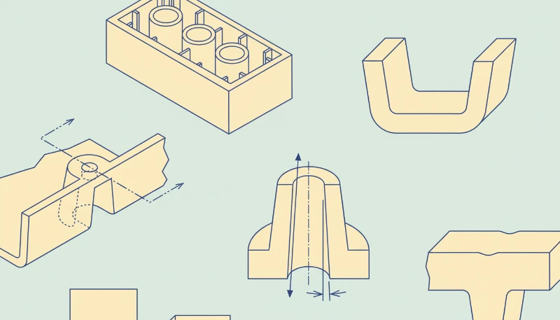
Injection molded product design is the work of turning a useful product idea into geometry that can fill, cool, eject, assemble, and repeat in production. A part can look simple in CAD yet still create sink marks, drag scratches, trapped gas, flash, broken ejector pins, or mold rework if the design ignores tooling and process limits.
This guide rebuilds the design principles for injection molding products around production reality. It focuses on wall thickness, ribs, угол осадки1, shutoffs, tolerance, material behavior, and review discipline, because those choices decide whether a tool runs stable after steel is cut.
Use it before design freeze, not after first shots. When our factory reviews a new plastic part, we try to find the mold risk while it is still a CAD decision, because a 0.3 mm geometry change before tooling is much cheaper than a welded insert or an emergency steel modification later.
- Design for molding starts with uniform material flow, predictable cooling, and safe ejection.
- Wall thickness, ribs, bosses, and corners should be sized as one connected system.
- Draft angle and parting strategy must be reviewed before tooling because they control release and flash risk.
- Tolerance should be assigned by function and process capability, not copied from machined-metal drawings.
- A short DFM review before mold build prevents many late-stage defects and cost surprises.
What are the core design principles for injection molding products?
The core design principles for injection molding products are the main categories or options explained in this section. The core design principles for injection molding products are uniform wall thickness, balanced flow length, controlled cooling, reliable ejection, realistic tolerance, and tool-safe geometry. These principles work together because plastic shrinks while it cools and because the mold must release the finished part without dragging or deformation.
Start by treating the part as a flow-and-cooling problem. A gate can only push molten material so far before pressure, shear, and cooling change the filling pattern. If one zone is much thicker than the rest, that zone stays hot longer, shrinks later, and often creates sink, voids, or local warpage.
The safest early review connects product function to manufacturing limits. A useful product spec says which surfaces are cosmetic, which dimensions control assembly, which areas can accept ejector marks, and which loads the part must survive. That information lets the designer and mold maker trade geometry, gate location, and material before the tool layout is fixed.
For a broader process foundation, use ZetarMold’s руководство по процессу литья под давлением. For tooling decisions such as parting line, slides, lifters, cooling, and steel-safe changes, connect the review to the injection mold guide. If the buyer is selecting a factory, the supplier sourcing guide helps turn those checks into sourcing questions.
“A molded part should be designed around melt flow, cooling, and ejection before cosmetic styling is locked.”Правда
This is true because the mold cannot correct every geometry problem after steel cutting. Styling, ribs, bosses, clips, and tolerance stacks all influence pressure loss, shrinkage, draft, and release force.
“Any plastic part can keep the same geometry as a CNC machined part if the material is strong enough.”Ложь
This is false because molding adds shrinkage, cooling gradients, ejector loads, parting constraints, and gate vestige. Material strength does not remove the need for molding-specific geometry.
| Principle | What to Check | Risk if Ignored |
|---|---|---|
| Wall control | Keep transitions gradual and avoid isolated mass | Sink, voids, warpage |
| Mold release | Add draft and avoid trapped undercuts | Drag marks, stuck parts |
| Functional tolerance | Limit tight tolerances to critical interfaces | High scrap and mold rework |
| Review timing | Run DFM before tool build | Late design changes |
A practical DFM pass should ask whether the nominal wall thickness2 is consistent enough for the chosen resin, whether the longest flow path can fill without overpacking, and whether the cosmetic face can be protected from gates and ejector marks. Our engineers usually flag high-risk zones first, then rank each fix by cost, lead time, and effect on product function.
How should wall thickness, ribs, and bosses be designed?
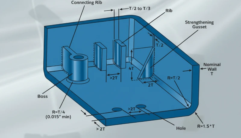
Wall thickness is the main control for cooling time, shrinkage, and local stress in a molded part. It should be as uniform as the product function allows, because thickness controls cooling time, shrinkage, and local stress. A nominal wall thickness is a target wall value used across the part so flow and cooling remain predictable instead of changing sharply from one region to another.
For many engineering thermoplastics, early concepts often start near 1.5 mm to 3.0 mm walls, then move after resin, flow length, stiffness, and drop-test needs are known. Thin sections may freeze before the cavity fills, while thick sections can hold heat and create visible sink on the cosmetic side.
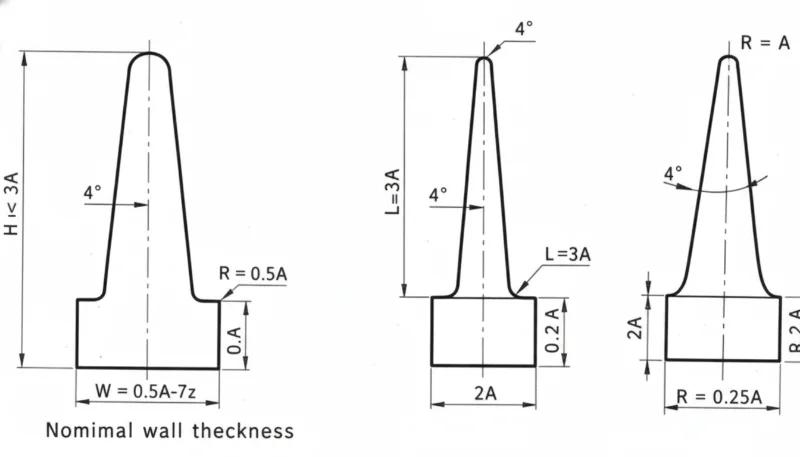
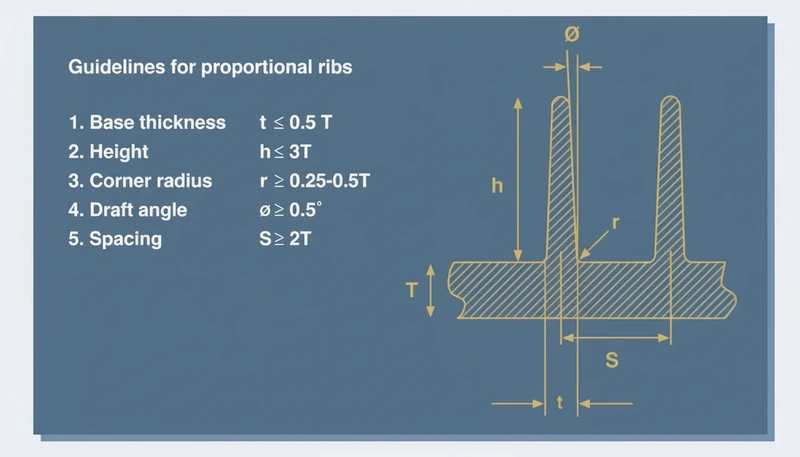
Ribs add stiffness without turning the part into one thick block. A common rib-to-wall ratio3 target is about 40% to 60% of the adjacent wall, with generous root radii and enough spacing for steel strength. If a rib is too thick, the outer surface can sink; if it is too tall and thin, filling and ejection become unstable.
Bosses need the same discipline. A screw boss should be connected with ribs or gussets, not a heavy cylinder sitting on a thin wall. The boss outside diameter, core pin strength, screw engagement, and ejection direction should be reviewed together so the design does not create short shots, burn marks, or broken core pins.
In our factory DFM reviews, a wall transition above about 30% of the nearby wall is usually marked for discussion. We also review rib bases under magnification after first shots because a small sink mark on a visible housing can be harder to sell than a small tooling change.
Corners should be rounded instead of sharp. Internal radii improve flow and reduce stress concentration, while external radii keep wall thickness consistent around the corner. A sharp internal corner may look clean in CAD, but it makes the polymer turn abruptly and can leave a weak point under impact or vibration.
When the part must remain stiff, combine ribs, material selection, and local geometry. The best design is rarely the thickest design. It is the design that puts material where load paths need it while keeping the cooling profile even enough for repeatable molding.
How do draft angle, parting line, and shutoffs reduce tooling risk?
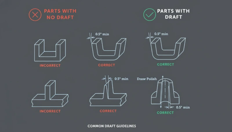
Draft angle is the clearance that helps a molded part release from the cavity or core. It reduces tooling risk by giving the molded part clearance as it leaves the cavity or core. Without enough draft angle, textured surfaces, deep ribs, and tall walls can rub against steel during ejection, causing drag marks, whitening, distortion, or stuck parts.
A typical early target is 1.0 degrees to 2.0 degrees per side for many smooth vertical faces, with more draft for texture or deep features. The final value depends on material shrinkage, surface finish, draw depth, tool polish, and whether the surface is cavity side or core side.
Parting line strategy should be chosen before the visual surface is locked. The parting line decides where flash may appear, where shutoff faces meet, and whether slides or lifters are needed. A beautiful product split can become expensive if it hides an unavoidable undercut or forces weak shutoff steel.
Shutoffs need enough angle and bearing area to survive repeated cycles. Very thin steel edges can chip, wear, or create flash after production starts. If a clip, window, vent, or snap requires a shutoff, the DFM review should check steel thickness, polishing access, and whether the feature can be redesigned for a safer mold action.
“Draft and parting line choices should be visible in the DFM review before the mold layout is approved.”Правда
This is true because these choices determine mold opening direction, slide count, shutoff wear, cosmetic marks, and ejection reliability. Late changes often require steel redesign.
“A zero-draft wall is acceptable when the CAD model has a smooth surface finish.”Ложь
This is false because even a smooth surface can grip steel after shrinkage. Zero draft increases ejection force and can mark or deform the part during release.
Use mold-open direction as a design constraint, not as an afterthought. Mark core side, cavity side, slide pulls, lifter motion, and expected witness lines on the model. When our engineers review a housing, we often color-code those areas so the customer can see where function, appearance, and tooling cost are competing.
This is also where buyer and supplier communication matters. A supplier who only quotes the drawing may miss hidden tool risk; a supplier who explains draw direction, steel safety, and first-shot risk gives the buyer a better basis for decision-making. That is why design review should sit inside the commercial RFQ workflow, not after purchase order release.
How should tolerances, material selection, and assembly features be balanced?
Tolerance balance is the process of matching dimensions, resin behavior, and assembly risk to real molding capability. Tolerance, material selection, and assembly features should be balanced by function, because every tight dimension adds process risk. GD&T is a drawing language that defines allowable variation in form, orientation, location, and runout so suppliers know which dimensions truly control assembly.
A molded plastic tolerance should consider resin shrinkage, tool temperature, moisture, filler content, part geometry, and measurement method. A 0.05 mm tolerance may be reasonable for a short steel feature in a machined part, but it can be unrealistic across a long molded span that cools unevenly.
Material choice changes the design rules. Glass-filled nylon may need stronger tool steel and more attention to fiber direction, while PC, ABS, PP, POM, PPSU, and PEEK each bring different shrinkage, stiffness, temperature resistance, and weld-line behavior. For early comparisons, review both product performance and molding stability.
Assembly features should be forgiving where possible. Snap fits need lead-in, strain control, and testable deflection limits. Screw bosses need core pin support and anti-splitting geometry. Living hinges, clips, seals, and ultrasonic welding ribs all require process-specific details, not generic wall additions.
| Design Area | Recommended Review | Factory Risk |
|---|---|---|
| Critical fit | Define datum and measurement method | Inspection dispute |
| Snap fit | Check strain and release direction | Cracking or weak retention |
| Босс | Check core pin and screw load | Short shot or split boss |
| Cosmetic face | Protect from gates and ejector marks | Visible defect |
For prototype-to-production programs, compare the molded design with the prototype process. A CNC prototype can hide molding risks because it does not need gate flow, shrinkage compensation, or ejection. The rapid prototyping injection molding explains when prototype tooling can reduce that gap before production steel.
Defect history should also feed the design review. If similar products had sink, flash, short shot, or warpage, use that evidence before the next mold is built. The common injection molding defects is useful when converting known failure modes into geometry checks.
Our team treats tolerance review as a risk-ranking exercise. We prefer to hold tight tolerance only where the product function needs it, then open noncritical surfaces to protect cycle stability, inspection speed, and long-term production yield.
Before approving steel, convert those tolerance choices into inspection notes. Define the datum surfaces, the fixture concept, the measurement temperature, and the sampling rule. This prevents a drawing from asking for precision that no one can measure consistently during production.
What design review workflow should buyers require before tooling?
A design review workflow is a staged DFM gate before tooling begins. It checks product function, resin choice, mold action, gate location, cooling, ejection, tolerance, and inspection. This workflow turns design principles into decisions that can be verified instead of opinions exchanged by email.
The first gate is a geometry review. Confirm wall map, rib map, boss layout, corner radii, draft, parting line, and undercuts. The second gate is a tooling review. Confirm cavity count, slide and lifter actions, gate type, cooling channel access, venting, steel safety, and expected maintenance points.
The third gate is a production review. Confirm resin drying, expected cycle time, cosmetic acceptance criteria, inspection fixtures, packaging loads, and change-control rules. A mold that passes sample approval but lacks a production plan can still fail when order volume increases.
Keep the review evidence append-only. Save marked screenshots, DFM comments, customer approvals, first-shot reports, and mold-change records. When a later defect appears, this history shows whether the issue came from design, tooling, material, process setup, or an undocumented change.
The best outcome is not a longer checklist. It is a shorter path from product requirement to stable production. When the design file, mold plan, and inspection criteria are aligned, the supplier can quote more accurately, the buyer can compare proposals more fairly, and the first production run has fewer avoidable surprises.
For rank-recovery content, this workflow also matters to search quality. Readers need a page that answers design questions directly, shows production evidence, and gives them a practical review sequence they can use on the next project. That combination is stronger than a generic list of plastic design tips.
It also gives the sales team a clearer inquiry path, because a buyer can attach drawings, highlight the risky features, and ask for a focused DFM response instead of sending only a price request.
Часто задаваемые вопросы
What is the most important design rule for injection molded products?
The most important rule is to design the part around consistent filling, cooling, and ejection instead of only around the final product shape. Uniform wall thickness, smooth transitions, realistic tolerance, and sufficient draft prevent many common molding failures. When those basics are ignored, the mold maker may still produce samples, but production can suffer from sink marks, warpage, stuck parts, flash, and unstable dimensions. This turns DFM into a shared checklist for both buyer and supplier and prevents late disputes about what the tool was expected to solve.
Какой угол съема должна иметь пластиковая деталь?
Полезной ранней целью часто является 1,0–2,0 градуса на сторону на гладких вертикальных стенках, но окончательный угол съема зависит от материала, текстуры, глубины вытяжки, усадки и требований к внешнему виду. Глубокие ребра, текстурированные поверхности и материалы с стекловолокном обычно требуют более консервативного анализа. Правильный вопрос не только в том, какой угол съема виден в CAD, но и в том, может деталь чисто выйти из формы для ожидаемого объема производства без следов задиров, побеления, деформации или чрезмерного усилия выталкивания. Глубина текстуры и доступ для полировки также должны учитываться в этом решении.
Почему ребра вызывают утяжения в литье под давлением?
Ребра вызывают утяжения, когда основание ребра создает локальное толстое сечение, которое охлаждается медленнее окружающей стенки. Когда эта тяжелая область усаживается, внешняя косметическая поверхность может втягиваться внутрь и показывать видимую впадину. Обычное решение — уменьшить толщину ребра, добавить достаточные радиусы, разделить одно тяжелое ребро на несколько более легких ребер или переместить элемент от критической внешней поверхности. Ребро должно улучшать жесткость без поведения как скрытого блока пластика, который замедляет охлаждение.
Должна ли литая пластиковая деталь использовать очень жесткие допуски на всех участках?
Нет. Жесткие допуски следует резервировать для функциональных интерфейсов, таких как уплотняющие поверхности, защелки, центровка шестерен, места расположения соединителей или базовые точки сборки. Некритичные поверхности должны использовать более широкие допуски, чтобы процесс литья оставался стабильным. Применение жестких допусков повсеместно увеличивает стоимость контроля, риск брака, время корректировки формы и вызывает непонимание поставщика без улучшения функциональности конечного продукта. Улучшенный чертеж отделяет критичные для функции размеры от косметических или зазоровых размеров и четко определяет ответственность за измерение. Это также помогает поставщику честно оценить контрольные приспособления, частоту выборки и ожидаемую способность процесса.
Когда следует проводить DFM-анализ в новом проекте литья под давлением?
DFM-анализ должен проводиться до окончательного утверждения стоимости формы и повторно до начала обработки стальной оснастки. Первый анализ выявляет геометрические и технологические риски, когда изменения дизайна еще недороги. Второй анализ подтверждает согласованную конструкцию формы, место расположения впуска, линию разъема, план выталкивания и требования к контролю. Ожидание до первых отливок превращает многие простые CAD-изменения в дорогостоящие модификации формы. Документированный анализ также дает покупателю более весомые доказательства при сравнении поставщиков и утверждении запуска оснастки. Он должен храниться вместе с чертежами, конструкцией формы и записями утверждения.
-
draft angle: Угол съема — это небольшой конус, применяемый к вертикальным поверхностям, чтобы литая деталь могла выйти из полости или сердечника с меньшим трением. ↩
-
толщина основной стенки: Толщина основной стенки — это целевое значение толщины стенки, используемое как базовое для анализа охлаждения, заполнения, жесткости и усадки в литой пластиковой детали. ↩
-
отношение ребра к стенке: Отношение ребра к стенке описывает связь между толщиной основания ребра и толщиной соседней основной стенки, чтобы жесткость могла увеличиваться без чрезмерного утяжения. ↩


