Projektowanie wyrobów formowanych wtryskowo polega na przekształceniu użytecznej koncepcji produktu w geometrię, która umożliwia prawidłowe wypełnienie gniazda, chłodzenie, wypchnięcie, montaż oraz powtarzalną produkcję. Detal może wyglądać prosto w systemie CAD, a mimo to powodować zapadnięcia, zarysowania przy wyjmowaniu, uwięzienie gazu, wypływki, pękanie wypychaczy lub konieczność przeróbki formy, jeśli projekt nie uwzględnia ograniczeń narzędziowych i procesowych.
Ten przewodnik przedstawia zasady projektowania wyrobów formowanych wtryskowo z perspektywy realiów produkcji. Koncentruje się na grubości ścianek, żebrach, kącie pochylenia1, odcięciach, tolerancjach, zachowaniu materiału i dyscyplinie przeglądów, ponieważ te decyzje przesądzają, czy po obróbce stali forma będzie pracować stabilnie.
Należy ją przeprowadzić przed zamrożeniem projektu, a nie po pierwszych wtryskach. Gdy nasz zakład analizuje nową część z tworzywa, staramy się zidentyfikować ryzyko związane z formą, dopóki można je jeszcze wyeliminować decyzją w modelu CAD, ponieważ zmiana geometrii o 0.3 mm przed wykonaniem oprzyrządowania kosztuje znacznie mniej niż późniejsze wykonanie spawanej wkładki lub awaryjna modyfikacja stali.
- Projektowanie pod kątem formowania zaczyna się od równomiernego przepływu materiału, przewidywalnego chłodzenia i bezpiecznego wypychania.
- Grubość ścianek, żebra, występy montażowe i naroża należy wymiarować jako jeden wzajemnie powiązany układ.
- Kąt pochylenia i strategię podziału formy należy zweryfikować przed wykonaniem oprzyrządowania, ponieważ decydują o wyjmowaniu części i ryzyku powstawania wypływki.
- Tolerancje należy przypisywać według funkcji i zdolności procesu, a nie kopiować z rysunków części obrabianych z metalu.
- Krótki przegląd DFM przed rozpoczęciem budowy formy zapobiega wielu wadom ujawniającym się na późnym etapie oraz nieoczekiwanym kosztom.
Jakie są podstawowe zasady projektowania wyrobów formowanych wtryskowo?
Podstawowe zasady projektowania wyrobów formowanych wtryskowo to główne kategorie lub warianty omówione w tej sekcji. Obejmują one równomierną grubość ścianek, zrównoważoną długość drogi przepływu, kontrolowane chłodzenie, niezawodne wypychanie, realistyczne tolerancje oraz geometrię bezpieczną dla formy. Zasady te są ze sobą powiązane, ponieważ tworzywo kurczy się podczas chłodzenia, a forma musi umożliwiać uwolnienie gotowej części bez zacierania ani odkształceń.
Najpierw potraktuj część jako zagadnienie przepływu i chłodzenia. Przewężka może przetłaczać stopiony materiał tylko na określoną odległość, zanim ciśnienie, ścinanie i chłodzenie zmienią sposób napełniania. Jeżeli jedna strefa jest znacznie grubsza od pozostałych, dłużej pozostaje gorąca, później się kurczy i często powoduje zapadnięcia, puste przestrzenie lub miejscowe wypaczenie.
Najbezpieczniej jest już na wczesnym etapie powiązać funkcję produktu z ograniczeniami produkcyjnymi. Przydatna specyfikacja produktu określa, które powierzchnie są estetyczne, które wymiary decydują o prawidłowym montażu, gdzie dopuszczalne są ślady po wypychaczach oraz jakie obciążenia musi wytrzymać część. Informacje te pozwalają projektantowi i producentowi formy wyważyć geometrię, położenie przewężki i dobór materiału, zanim zostanie ustalony układ formy.
Szersze podstawy procesu zawiera przewodnik ZetarMold po procesie formowania wtryskowego. Decyzje dotyczące oprzyrządowania, takie jak linia podziału, suwaki, wypychacze skośne, chłodzenie i poprawki z zachowaniem zapasu stali, należy powiązać z przewodnikiem po formach wtryskowych. Jeśli nabywca wybiera zakład produkcyjny, przewodnik po wyborze dostawcy pomaga przekształcić te kontrole w pytania zakupowe.
"Projekt części formowanej należy oprzeć na przepływie stopionego tworzywa, chłodzeniu i wypychaniu, zanim zostanie zatwierdzona stylistyka."True
To prawda, ponieważ po rozpoczęciu obróbki stali forma nie skoryguje każdego problemu geometrycznego. Stylistyka, żebra, słupki montażowe, zatrzaski i łańcuchy tolerancji wpływają na straty ciśnienia, skurcz, pochylenia i siłę potrzebną do uwolnienia części.
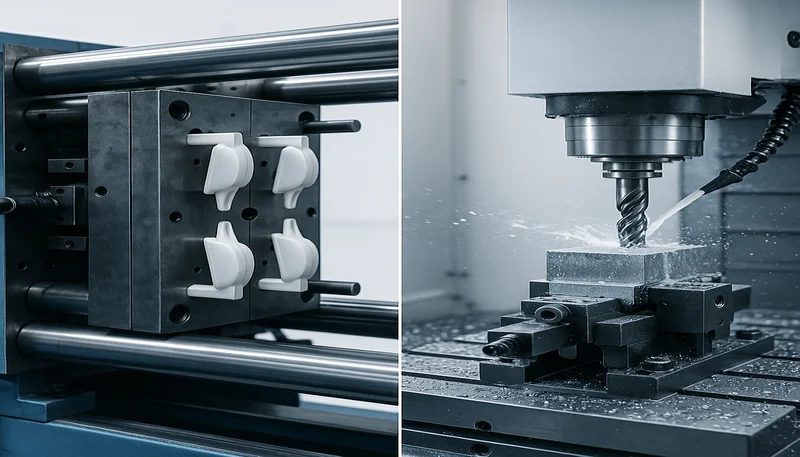
"Każdy detal z tworzywa może zachować geometrię części obrabianej CNC, jeśli materiał jest wystarczająco wytrzymały."False
To nieprawda, ponieważ formowanie wprowadza skurcz, gradienty chłodzenia, obciążenia od wypychaczy, ograniczenia wynikające z podziału formy i pozostałość po przewężce. Wytrzymałość materiału nie eliminuje potrzeby stosowania geometrii dostosowanej do formowania.
| Zasada | Co sprawdzić | Ryzyko w przypadku zignorowania |
|---|---|---|
| Kontrola ścianek | Stosuj łagodne przejścia i unikaj miejscowych nagromadzeń materiału | Zapadnięcia, pustki, odkształcenia |
| Środek antyadhezyjny do form | Dodaj pochylenie i unikaj uwięzionych podcięć | Ślady zatarcia, zakleszczone części |
| Tolerancja funkcjonalna | Stosuj wąskie tolerancje wyłącznie na krytycznych interfejsach | Wysoki poziom braków i przeróbek formy |
| Termin przeglądu | Przeprowadź analizę DFM przed wykonaniem formy | Późne zmiany konstrukcyjne |
Praktyczny przegląd DFM powinien sprawdzić, czy nominalna grubość ścianki2 jest dostatecznie jednolita dla wybranej żywicy, czy najdłuższa droga płynięcia zostanie wypełniona bez nadmiernego docisku oraz czy powierzchnię kosmetyczną można ochronić przed śladami przewężek i wypychaczy. Nasi inżynierowie zwykle najpierw wskazują obszary wysokiego ryzyka, a następnie klasyfikują każdą poprawkę według kosztu, terminu i wpływu na funkcję produktu.
Jak należy projektować grubość ścianek, żebra i słupki montażowe?
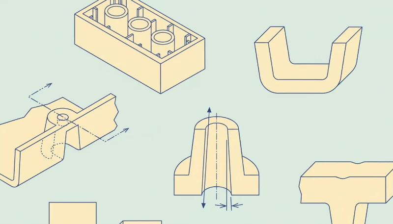
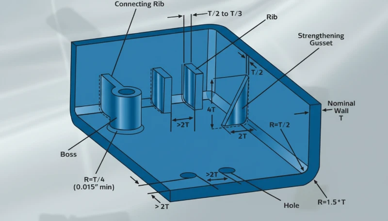
Grubość ścianki jest głównym parametrem wpływającym na czas chłodzenia, skurcz i naprężenia miejscowe w wyprasce. Powinna być tak równomierna, jak pozwala na to funkcja wyrobu, ponieważ determinuje czas chłodzenia, skurcz i naprężenia miejscowe. Nominalna grubość ścianki to wartość docelowa stosowana w całej części, dzięki której przepływ i chłodzenie pozostają przewidywalne zamiast gwałtownie zmieniać się między poszczególnymi obszarami.
W przypadku wielu termoplastów konstrukcyjnych wstępne koncepcje często zakładają ścianki o grubości od 1.5 mm do 3.0 mm, które następnie koryguje się po określeniu rodzaju żywicy, długości drogi płynięcia, wymaganej sztywności i wymagań próby upadku. Cienkie przekroje mogą zastygnąć przed wypełnieniem gniazda, natomiast grube przekroje mogą zatrzymywać ciepło i powodować widoczne zapadnięcia po stronie dekoracyjnej.
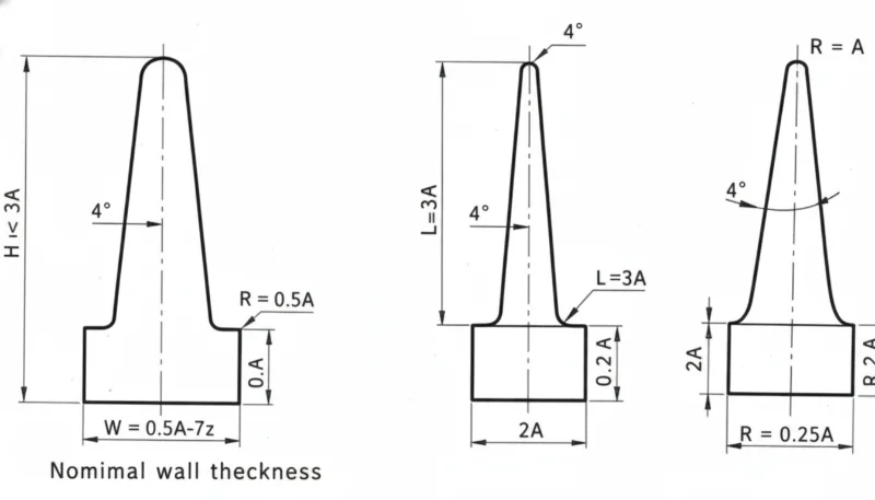
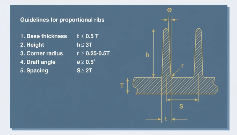
Żebra zwiększają sztywność bez przekształcania części w jeden gruby blok. Typowy docelowy stosunek grubości żebra do ścianki3 wynosi około 40%–60% grubości sąsiedniej ścianki, przy dużych promieniach u podstawy i rozstawie zapewniającym wytrzymałość stali. Zbyt grube żebro może powodować zapadnięcie powierzchni zewnętrznej, a zbyt wysokie i cienkie — niestabilne napełnianie i wyrzucanie.
Tuleje pod wkręty wymagają takiej samej dyscypliny projektowej. Tuleję należy połączyć żebrami lub zastrzałami, zamiast projektować masywny cylinder osadzony na cienkiej ściance. Średnicę zewnętrzną tulei, wytrzymałość trzpienia rdzeniowego, długość zazębienia wkrętu i kierunek wypychania należy analizować łącznie, aby konstrukcja nie powodowała niedolewów, przypaleń ani pękania trzpieni rdzeniowych.
Podczas przeglądów DFM w naszej fabryce przejście grubości przekraczające około 30% grubości sąsiedniej ścianki jest zwykle oznaczane do omówienia. Po pierwszych próbach oglądamy również podstawy żeber w powiększeniu, ponieważ niewielkie zapadnięcie na widocznej obudowie może być trudniejsze do zaakceptowania przez klienta niż drobna modyfikacja oprzyrządowania.
Naroża powinny być zaokrąglone, a nie ostre. Promienie wewnętrzne poprawiają przepływ i zmniejszają koncentrację naprężeń, natomiast promienie zewnętrzne pozwalają zachować stałą grubość ścianki wokół naroża. Ostre naroże wewnętrzne może wyglądać estetycznie w modelu CAD, ale wymusza gwałtowną zmianę kierunku przepływu polimeru i może utworzyć słaby punkt podatny na uderzenia lub drgania.
Gdy część musi zachować sztywność, należy połączyć zastosowanie żeber, odpowiedni dobór materiału i lokalne ukształtowanie geometrii. Najlepszy projekt rzadko jest projektem o najgrubszych ściankach. To projekt, w którym materiał znajduje się tam, gdzie wymagają tego ścieżki przenoszenia obciążeń, a profil chłodzenia pozostaje wystarczająco równomierny, by zapewnić powtarzalne formowanie.
W jaki sposób kąt pochylenia, linia podziału i zamknięcia formy ograniczają ryzyko związane z oprzyrządowaniem?
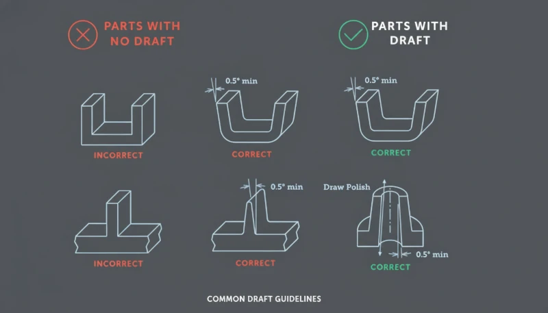
Kąt pochylenia zapewnia luz ułatwiający wyjęcie uformowanej części z gniazda lub rdzenia. Ogranicza ryzyko dla oprzyrządowania, zapewniając części luz podczas opuszczania gniazda lub rdzenia. Niedostateczny kąt sprawia, że powierzchnie teksturowane, głębokie żebra i wysokie ścianki mogą ocierać o stal podczas wypychania, powodując ślady tarcia, zbielenia, odkształcenia lub zakleszczenie części.
Typowym celem początkowym dla wielu gładkich powierzchni pionowych jest pochylenie od 1.0 stopnia do 2.0 stopni na stronę; większe pochylenie stosuje się przy powierzchniach teksturowanych lub głębokich elementach. Ostateczna wartość zależy od skurczu materiału, wykończenia powierzchni, głębokości wyciągania, stopnia wypolerowania narzędzia oraz od tego, czy powierzchnia znajduje się po stronie gniazda, czy rdzenia.
Strategię linii podziału należy wybrać przed zatwierdzeniem powierzchni wizualnej. Linia podziału określa miejsce możliwych nadlewek, styku powierzchni zamykających oraz potrzebę użycia suwaków lub wypychaczy skośnych. Atrakcyjny podział produktu może okazać się kosztowny, jeśli ukrywa nieuniknione podcięcie lub wymusza słabą stal zamykającą.
Powierzchnie odcinające muszą mieć odpowiedni kąt i powierzchnię styku, aby wytrzymać wielokrotne cykle. Bardzo cienkie krawędzie stalowe mogą się wykruszać, zużywać lub powodować wypływki po rozpoczęciu produkcji. Jeśli zaczep, okno, otwór wentylacyjny lub zatrzask wymaga odcięcia, podczas analizy DFM należy sprawdzić grubość stali, dostęp do polerowania oraz możliwość przeprojektowania tej cechy w celu uzyskania bezpieczniejszego mechanizmu formy.
"Dobór pochylenia i linii podziału powinien być widoczny w przeglądzie DFM przed zatwierdzeniem układu formy."True
To prawda, ponieważ wybory te określają kierunek otwierania formy, liczbę suwaków, zużycie powierzchni odcinających, ślady na powierzchniach dekoracyjnych oraz niezawodność wypychania. Późne zmiany często wymagają przeprojektowania elementów stalowych formy.
„Ścianka bez pochylenia jest dopuszczalna, jeżeli model CAD przewiduje gładkie wykończenie powierzchni.”False
To nieprawda, ponieważ nawet gładka powierzchnia może po skurczu zacisnąć się na stali. Brak pochylenia zwiększa siłę wypychania i może pozostawić ślady lub odkształcić detal podczas wyjmowania.
Kierunek otwierania formy traktuj jako ograniczenie projektowe, a nie kwestię rozpatrywaną na końcu. Zaznacz w modelu stronę rdzenia, stronę gniazda, kierunki ruchu suwaków i wypychaczy skośnych oraz przewidywane ślady po łączeniu elementów formy. Podczas przeglądu projektu obudowy nasi inżynierowie często oznaczają te obszary kolorami, aby klient widział, gdzie występują kompromisy między funkcjonalnością, wyglądem a kosztem oprzyrządowania.
W tym miejscu znaczenie ma również komunikacja między nabywcą a dostawcą. Dostawca, który wycenia tylko rysunek, może przeoczyć ukryte ryzyko związane z formą; dostawca wyjaśniający kierunek odformowania, zapas stali i ryzyko pierwszego wtrysku daje nabywcy lepszą podstawę do decyzji. Dlatego przegląd projektu powinien być częścią handlowego procesu RFQ, a nie następować po wystawieniu zamówienia.
Jak zrównoważyć tolerancje, dobór materiału i elementy montażowe?
Równoważenie tolerancji polega na dopasowaniu wymiarów, zachowania tworzywa i ryzyka montażowego do rzeczywistych możliwości procesu formowania. Tolerancje, dobór materiału i cechy montażowe należy równoważyć z uwzględnieniem funkcji, ponieważ każdy rygorystycznie tolerowany wymiar zwiększa ryzyko procesowe. GD&T to język dokumentacji technicznej, który określa dopuszczalne odchyłki kształtu, orientacji, położenia i bicia, dzięki czemu dostawcy wiedzą, które wymiary rzeczywiście decydują o poprawności montażu.
Tolerancja formowanej części z tworzywa sztucznego powinna uwzględniać skurcz żywicy, temperaturę formy, wilgotność, zawartość napełniacza, geometrię części oraz metodę pomiaru. Tolerancja 0.05 mm może być uzasadniona dla krótkiego elementu stalowego w części obrabianej skrawaniem, lecz nierealistyczna na dużej rozpiętości formowanego detalu, który stygnie nierównomiernie.
Wybór materiału zmienia zasady projektowania. Nylon wzmacniany włóknem szklanym może wymagać wytrzymalszej stali narzędziowej i większej uwagi poświęconej orientacji włókien, natomiast PC, ABS, PP, POM, PPSU i PEEK różnią się skurczem, sztywnością, odpornością temperaturową oraz zachowaniem linii łączenia. We wstępnych porównaniach należy uwzględnić zarówno właściwości użytkowe produktu, jak i stabilność procesu formowania.
Elementy montażowe powinny w miarę możliwości tolerować odchylenia. Zatrzaski wymagają fazy wprowadzającej, kontroli odkształcenia i sprawdzalnych granic ugięcia. Tuleje pod wkręty wymagają podparcia trzpieniem rdzeniowym i geometrii zapobiegającej pękaniu. Zawiasy integralne, klipsy, uszczelnienia i żebra do zgrzewania ultradźwiękowego wymagają rozwiązań właściwych dla danego procesu, a nie ogólnego zwiększania grubości ścianek.
| Obszar projektowy | Zalecany przegląd | Ryzyko związane z zakładem produkcyjnym |
|---|---|---|
| Pasowanie krytyczne | Określ bazę i metodę pomiaru | Spór dotyczący kontroli jakości |
| Połączenie zatrzaskowe | Sprawdź odkształcenie i kierunek uwalniania | Pękanie lub słabe osadzenie |
| Szef | Sprawdź obciążenie trzpienia rdzeniowego i śruby | Niedolew lub pęknięty słupek |
| Powierzchnia dekoracyjna | Chronić przed śladami przewężek i wypychaczy | Widoczna wada |
W programach prowadzonych od prototypu do produkcji należy porównać konstrukcję części formowanej z procesem wykonania prototypu. Prototyp obrabiany CNC może maskować ryzyka związane z formowaniem, ponieważ nie wymaga uwzględnienia przepływu od przewężki, kompensacji skurczu ani wypychania. Szybkie prototypowanie metodą formowania wtryskowego wyjaśnia, kiedy oprzyrządowanie prototypowe może zmniejszyć tę lukę przed wykonaniem formy ze stali produkcyjnej.
Historia wad powinna być również uwzględniana w przeglądzie konstrukcji. Jeżeli w podobnych wyrobach występowały zapadnięcia, wypływki, niedolewy lub odkształcenia, należy wykorzystać te dane przed wykonaniem kolejnej formy. Materiał dotyczący typowych wad formowania wtryskowego pomaga przełożyć znane mechanizmy uszkodzeń na kontrolę geometrii.
Nasz zespół traktuje przegląd tolerancji jako proces klasyfikacji ryzyka. Wąskie tolerancje utrzymujemy wyłącznie tam, gdzie wymaga tego funkcja produktu, natomiast na powierzchniach niekrytycznych stosujemy szersze tolerancje, aby zapewnić stabilność cyklu, sprawną kontrolę i wysoką długoterminową wydajność produkcji.
Przed zatwierdzeniem stali przełóż wybrane tolerancje na uwagi kontrolne. Określ powierzchnie bazowe, koncepcję przyrządu, temperaturę pomiaru i regułę pobierania próbek. Zapobiega to sytuacji, w której rysunek wymaga precyzji niemożliwej do konsekwentnego zmierzenia podczas produkcji.
Jakiego procesu przeglądu projektu powinni wymagać nabywcy przed rozpoczęciem wykonywania oprzyrządowania?
Procedura przeglądu projektu jest etapową bramką DFM poprzedzającą rozpoczęcie budowy formy. Obejmuje sprawdzenie funkcji wyrobu, doboru tworzywa, mechaniki formy, położenia przewężki, chłodzenia, wypychania, tolerancji i kontroli. Procedura ta przekłada zasady projektowe na weryfikowalne decyzje, zamiast pozostawiać je w sferze opinii wymienianych pocztą elektroniczną.
Pierwszym etapem jest przegląd geometrii. Potwierdź mapę ścianek, mapę żeber, układ słupków, promienie naroży, pochylenia, linię podziału i podcięcia. Drugim etapem jest przegląd oprzyrządowania. Potwierdź liczbę gniazd, działanie suwaków i wypychaczy skośnych, typ przewężki, dostęp do kanałów chłodzących, odpowietrzanie, naddatki stali oraz przewidywane punkty konserwacji.
Trzeci punkt kontrolny to przegląd produkcyjny. Należy potwierdzić warunki suszenia żywicy, oczekiwany czas cyklu, kryteria akceptacji wyglądu, przyrządy kontrolne, obciążenia opakowań oraz zasady kontroli zmian. Forma, która przeszła zatwierdzenie próbek, lecz nie ma planu produkcji, może nadal zawieść po zwiększeniu wolumenu zamówień.
Dokumentację przeglądu prowadź wyłącznie przez dopisywanie. Zachowuj oznaczone zrzuty ekranu, uwagi DFM, zatwierdzenia klienta, raporty z pierwszych prób i rejestry zmian formy. Gdy później pojawi się wada, historia pokaże, czy źródłem był projekt, narzędzie, materiał, ustawienia procesu czy nieudokumentowana zmiana.
Najlepszym rezultatem nie jest dłuższa lista kontrolna, lecz krótsza droga od wymagań produktowych do stabilnej produkcji. Gdy plik konstrukcyjny, plan formy i kryteria kontroli są ze sobą zgodne, dostawca może dokładniej przygotować ofertę, nabywca może rzetelniej porównać propozycje, a podczas pierwszej serii produkcyjnej występuje mniej możliwych do uniknięcia niespodzianek.
W przypadku treści służących odbudowie pozycji w wynikach wyszukiwania ten sposób pracy ma również znaczenie dla ich jakości. Czytelnik potrzebuje strony, która bezpośrednio odpowiada na pytania projektowe, przedstawia dowody z produkcji i podaje praktyczną kolejność weryfikacji możliwą do zastosowania w kolejnym projekcie. Takie połączenie jest bardziej wartościowe niż ogólna lista wskazówek dotyczących projektowania części z tworzyw sztucznych.
Zapewnia to również zespołowi sprzedaży bardziej przejrzystą ścieżkę obsługi zapytania, ponieważ kupujący może załączyć rysunki, wskazać ryzykowne cechy i poprosić o ukierunkowaną analizę DFM, zamiast przesyłać wyłącznie zapytanie o cenę.
Często zadawane pytania
Jaka jest najważniejsza zasada projektowania wyrobów formowanych wtryskowo?
Najważniejszą zasadą jest projektowanie detalu pod kątem powtarzalnego wypełniania, chłodzenia i wyrzutu, a nie wyłącznie jego końcowego kształtu. Jednolita grubość ścianek, płynne przejścia, realistyczne tolerancje i wystarczające pochylenie zapobiegają wielu typowym wadom formowania. Jeśli te podstawy zostaną pominięte, producent formy może nadal wykonać próbki, lecz produkcja może być obciążona zapadnięciami, paczeniem, zakleszczaniem detali, wypływkami i niestabilnością wymiarową. DFM staje się dzięki temu wspólną listą kontrolną nabywcy i dostawcy oraz zapobiega późnym sporom o to, jakie problemy miało rozwiązać oprzyrządowanie.
Jakie pochylenie technologiczne powinien mieć detal z tworzywa sztucznego?
Przydatnym wczesnym celem jest często 1,0 do 2,0 stopni na stronę na gładkich ściankach pionowych, ale ostateczny kąt odciągu zależy od materiału, faktury, głębokości wyciągania, skurczu i wymagań kosmetycznych. Głębokie żebra, powierzchnie teksturowane i materiały wypełnione szkłem zwykle wymagają bardziej konserwatywnej analizy. Prawidłowe pytanie to nie tylko to, ile odciągu jest widoczne w CAD, ale czy część może być czysto zwolniona dla oczekiwanej wielkości produkcji bez śladów ciągnięcia, bielenia, deformacji lub nadmiernej siły wypychacza. Głębokość tekstury i dostęp do polerowania również powinny być uwzględnione w tej decyzji.
Dlaczego żebra powodują wgłębienia (sink marks) w formowaniu wtryskowym?
Żebra powodują wgłębienia, gdy podstawa żebra tworzy lokalny gruby przekrój, który stygnie wolniej niż otaczająca ścianka. Gdy ten obszar o większej masie kurczy się, zewnętrzna powierzchnia kosmetyczna może zostać wciągnięta do wewnątrz i pokazać widoczne zagłębienie. Typowym rozwiązaniem jest zmniejszenie grubości żebra, dodanie dużych promieni zaokrągleń, podzielenie jednego ciężkiego żebra na kilka lżejszych lub przeniesienie elementu z dala od krytycznej powierzchni wizualnej. Żebro powinno zwiększać sztywność, nie zachowując się jak ukryty blok plastiku opóźniający chłodzenie.
Czy formowana część z tworzywa sztucznego powinna mieć wszędzie bardzo wąskie tolerancje?
Nie. Wąskie tolerancje powinny być zarezerwowane dla interfejsów funkcjonalnych, takich jak powierzchnie uszczelniające, zaczepy zatrzaskowe, wyrównanie kół zębatych, lokalizacje złączy lub daty montażowe. Powierzchnie niekrytyczne powinny mieć szersze tolerancje, aby proces formowania mógł pozostać stabilny. Stosowanie wąskich tolerancji wszędzie zwiększa koszt kontroli, ryzyko braków, czas regulacji formy i dezorientację dostawcy, nie poprawiając funkcji końcowego produktu. Lepszy rysunek oddziela wymiary krytyczne dla funkcji od wymiarów kosmetycznych lub luzów i jasno określa odpowiedzialność pomiarową. Pomaga to również dostawcy uczciwie wycenić przyrządy kontrolne, częstotliwość próbkowania i oczekiwaną zdolność procesu.
Kiedy powinien odbyć się przegląd DFM w nowym projekcie formowania wtryskowego?
Przegląd DFM powinien odbyć się przed finalizacją wyceny formy i ponownie przed cięciem stali narzędziowej. Pierwszy przegląd identyfikuje ryzyka geometryczne i procesowe, gdy zmiany projektowe są jeszcze niedrogie. Drugi przegląd potwierdza uzgodniony układ formy, lokalizację bramki, linię podziału, plan wypychania i wymagania kontrolne. Czekanie do pierwszych odlewów zamienia wiele prostych zmian CAD w kosztowne modyfikacje formy. Udokumentowany przegląd daje również kupującemu lepsze dowody przy porównywaniu dostawców i zatwierdzaniu uruchomienia narzędzia. Powinien być przechowywany wraz z rysunkami, układem formy i dokumentami zatwierdzenia.
kąt pochylenia: Kąt pochylenia to niewielkie nachylenie powierzchni pionowych, dzięki któremu uformowana część może oddzielić się od gniazda lub rdzenia z mniejszym tarciem. ↩
nominalna grubość ścianki: Nominalna grubość ścianki to docelowa wartość stanowiąca punkt odniesienia przy ocenie chłodzenia, napełniania, sztywności i skurczu formowanej części z tworzywa. ↩
stosunek grubości żebra do ścianki: Stosunek grubości żebra do ścianki opisuje relację między grubością podstawy żebra a sąsiednią nominalną ścianką, pozwalając zwiększyć sztywność bez nadmiernych zapadnięć. ↩