 콘텐츠로 건너뛰기

Injection molded product design is the work of turning a useful product idea into geometry that can fill, cool, eject, assemble, and repeat in production. A part can look simple in CAD yet still create sink marks, drag scratches, trapped gas, flash, broken ejector pins, or mold rework if the design ignores tooling and process limits.
This guide rebuilds the design principles for injection molding products around production reality. It focuses on wall thickness, ribs, 구배 각도1, shutoffs, tolerance, material behavior, and review discipline, because those choices decide whether a tool runs stable after steel is cut.
Use it before design freeze, not after first shots. When our factory reviews a new plastic part, we try to find the mold risk while it is still a CAD decision, because a 0.3 mm geometry change before tooling is much cheaper than a welded insert or an emergency steel modification later.
- Design for molding starts with uniform material flow, predictable cooling, and safe ejection.
- Wall thickness, ribs, bosses, and corners should be sized as one connected system.
- Draft angle and parting strategy must be reviewed before tooling because they control release and flash risk.
- Tolerance should be assigned by function and process capability, not copied from machined-metal drawings.
- A short DFM review before mold build prevents many late-stage defects and cost surprises.
What are the core design principles for injection molding products?
The core design principles for injection molding products are the main categories or options explained in this section. The core design principles for injection molding products are uniform wall thickness, balanced flow length, controlled cooling, reliable ejection, realistic tolerance, and tool-safe geometry. These principles work together because plastic shrinks while it cools and because the mold must release the finished part without dragging or deformation.
Start by treating the part as a flow-and-cooling problem. A gate can only push molten material so far before pressure, shear, and cooling change the filling pattern. If one zone is much thicker than the rest, that zone stays hot longer, shrinks later, and often creates sink, voids, or local warpage.
The safest early review connects product function to manufacturing limits. A useful product spec says which surfaces are cosmetic, which dimensions control assembly, which areas can accept ejector marks, and which loads the part must survive. That information lets the designer and mold maker trade geometry, gate location, and material before the tool layout is fixed.
For a broader process foundation, use ZetarMold’s 사출 성형 공정 가이드. For tooling decisions such as parting line, slides, lifters, cooling, and steel-safe changes, connect the review to the injection mold guide. If the buyer is selecting a factory, the supplier sourcing guide helps turn those checks into sourcing questions.
“A molded part should be designed around melt flow, cooling, and ejection before cosmetic styling is locked.”True
This is true because the mold cannot correct every geometry problem after steel cutting. Styling, ribs, bosses, clips, and tolerance stacks all influence pressure loss, shrinkage, draft, and release force.
“Any plastic part can keep the same geometry as a CNC machined part if the material is strong enough.”False
This is false because molding adds shrinkage, cooling gradients, ejector loads, parting constraints, and gate vestige. Material strength does not remove the need for molding-specific geometry.
| Principle | What to Check | Risk if Ignored |
|---|---|---|
| Wall control | Keep transitions gradual and avoid isolated mass | Sink, voids, warpage |
| Mold release | Add draft and avoid trapped undercuts | Drag marks, stuck parts |
| Functional tolerance | Limit tight tolerances to critical interfaces | High scrap and mold rework |
| Review timing | Run DFM before tool build | Late design changes |
A practical DFM pass should ask whether the nominal wall thickness2 is consistent enough for the chosen resin, whether the longest flow path can fill without overpacking, and whether the cosmetic face can be protected from gates and ejector marks. Our engineers usually flag high-risk zones first, then rank each fix by cost, lead time, and effect on product function.
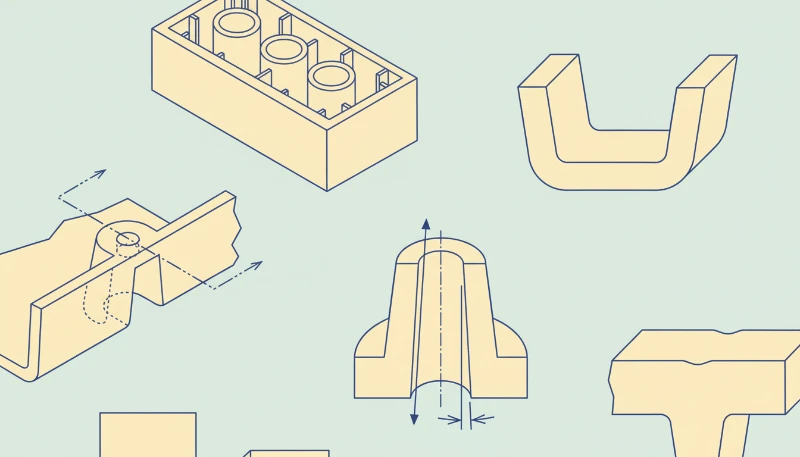
How should wall thickness, ribs, and bosses be designed?
Wall thickness is the main control for cooling time, shrinkage, and local stress in a molded part. It should be as uniform as the product function allows, because thickness controls cooling time, shrinkage, and local stress. A nominal wall thickness is a target wall value used across the part so flow and cooling remain predictable instead of changing sharply from one region to another.
For many engineering thermoplastics, early concepts often start near 1.5 mm to 3.0 mm walls, then move after resin, flow length, stiffness, and drop-test needs are known. Thin sections may freeze before the cavity fills, while thick sections can hold heat and create visible sink on the cosmetic side.
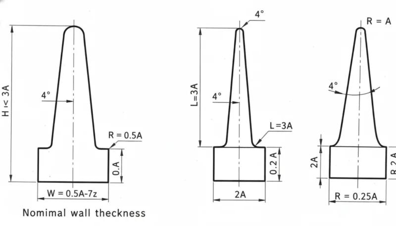
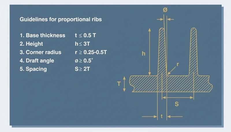
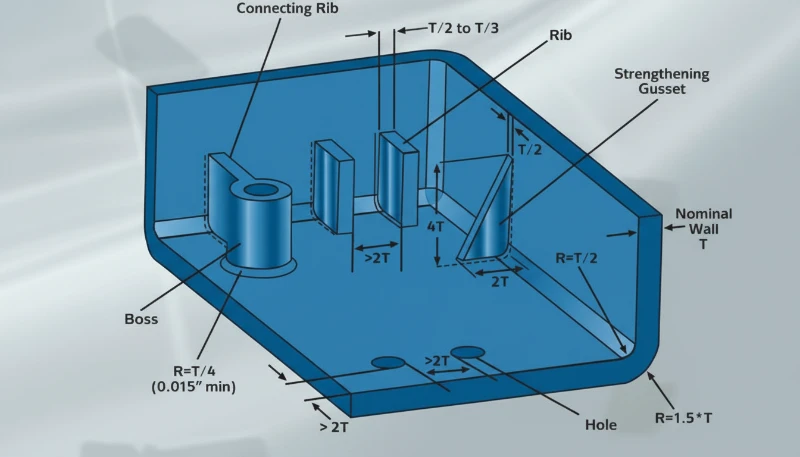
Ribs add stiffness without turning the part into one thick block. A common rib-to-wall ratio3 target is about 40% to 60% of the adjacent wall, with generous root radii and enough spacing for steel strength. If a rib is too thick, the outer surface can sink; if it is too tall and thin, filling and ejection become unstable.
Bosses need the same discipline. A screw boss should be connected with ribs or gussets, not a heavy cylinder sitting on a thin wall. The boss outside diameter, core pin strength, screw engagement, and ejection direction should be reviewed together so the design does not create short shots, burn marks, or broken core pins.
In our factory DFM reviews, a wall transition above about 30% of the nearby wall is usually marked for discussion. We also review rib bases under magnification after first shots because a small sink mark on a visible housing can be harder to sell than a small tooling change.
Corners should be rounded instead of sharp. Internal radii improve flow and reduce stress concentration, while external radii keep wall thickness consistent around the corner. A sharp internal corner may look clean in CAD, but it makes the polymer turn abruptly and can leave a weak point under impact or vibration.
When the part must remain stiff, combine ribs, material selection, and local geometry. The best design is rarely the thickest design. It is the design that puts material where load paths need it while keeping the cooling profile even enough for repeatable molding.
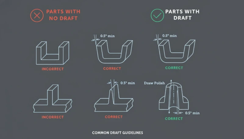
드래프트 각도, 파팅 라인, 셧오프가 금형 위험을 어떻게 줄이나요?
드래프트 각도는 성형품이 캐비티나 코어에서 떨어질 수 있도록 돕는 간격입니다. 성형품이 캐비티나 코어를 떠날 때 간격을 제공함으로써 공구 위험을 줄입니다. 충분한 드래프트 각도가 없으면 텍스처 표면, 깊은 리브, 높은 벽이 이젝션 중 강철에 문질러져 끌림 자국, 표면 백화, 변형 또는 부품 고착을 유발할 수 있습니다.
많은 매끄러운 수직면의 경우 초기 목표는 일반적으로 측면당 1.0도에서 2.0도이며, 텍스처나 깊은 형상이 있는 경우 더 많은 드래프트가 필요합니다. 최종 값은 재료 수축률, 표면 마감, 드로우 깊이, 공구 연마 상태, 그리고 표면이 캐비티 측인지 코어 측인지에 따라 달라집니다.
파팅 라인 전략은 시각적 표면이 확정되기 전에 선택되어야 합니다. 파팅 라인은 플래시가 나타날 수 있는 위치, 셔트오프 면이 만나는 위치, 슬라이드나 리프터가 필요한지 여부를 결정합니다. 피할 수 없는 언더컷을 숨기거나 약한 셔트오프 강철을 강제하는 경우 아름다운 제품 분할은 비용이 많이 들 수 있습니다.
셔트오프는 반복 주기를 견디기에 충분한 각도와 베어링 면적이 필요합니다. 매우 얇은 강철 모서리는 생산 시작 후 깨어지거나 마모되거나 플래시를 생성할 수 있습니다. 클립, 창, 통풍구, 스냅에 셔트오프가 필요한 경우 DFM 검토는 강철 두께, 연마 접근성, 더 안전한 금형 동작을 위해 구조를 재설계할 수 있는지 여부를 확인해야 합니다.
“드래프트 및 파팅 라인 선택은 금형 레이아웃이 승인되기 전에 DFM 검토에서 확인 가능해야 합니다.”True
이러한 선택은 금형 개방 방향, 슬라이드 수, 셧오프 마모, 코스메틱 마크, 이젝션 신뢰성을 결정하기 때문에 사실입니다. 후기 변경은 종종 강철 재설계가 필요합니다.
“CAD 모델에 매끄러운 표면 마감이 있을 때 제로 드래프트 벽은 허용됩니다.”False
이는 거짓입니다. 매끄러운 표면도 수축 후 강철을 잡을 수 있기 때문입니다. 제로 드래프트는 이젝션 힘을 증가시키고 부품이 떨어질 때 표시하거나 변형시킬 수 있습니다.
금형 개방 방향을 사후 고려가 아닌 설계 제약 조건으로 활용하세요. 모델에 코어 측, 캐비티 측, 슬라이드 풀, 리프터 동작, 예상되는 증거선을 표시합니다. 우리 엔지니어들이 하우징을 검토할 때는 기능, 외관, 금형 비용이 상충되는 부분을 고객이 볼 수 있도록 해당 영역을 색상으로 구분합니다.
이것은 또한 구매자와 공급자 간의 의사소통이 중요한 부분입니다. 도면만 견적하는 공급자는 숨겨진 공구 위험을 놓칠 수 있습니다. 드로우 방향, 강철 안전성, 첫 샷 위험을 설명하는 공급자는 구매자에게 더 나은 의사 결정 근거를 제공합니다. 이것이 설계 검토가 구매 주문 발행 후가 아닌 상업적 RFQ 워크플로우 내에 위치해야 하는 이유입니다.
공차, 재료 선택, 조립 특징은 어떻게 균형을 맞춰야 하나요?
공차 균형은 치수, 수지 거동, 조립 위험을 실제 성형 능력에 맞추는 과정입니다. 공차, 재료 선택, 조립 구조는 기능에 따라 균형을 맞춰야 합니다. 모든 엄격한 치수는 공정 위험을 증가시키기 때문입니다. GD&T는 공급업체가 조립을 실제로 제어하는 치수를 알 수 있도록 형상, 방향, 위치, 런아웃의 허용 변동을 정의하는 도면 언어입니다.
성형 플라스틱 공차는 수지 수축률, 금형 온도, 습기, 충전제 함량, 부품 형상, 측정 방법을 고려해야 합니다. 0.05mm 공차는 가공 부품의 짧은 강철 형상에는 합리적일 수 있지만, 불균일하게 냉각되는 긴 성형 스팬에서는 비현실적일 수 있습니다.
재료 선택은 설계 규칙을 변경합니다. 유리 섬유 강화 나일론은 더 강한 공구강과 섬유 방향에 대한 더 많은 주의가 필요할 수 있는 반면, PC, ABS, PP, POM, PPSU, PEEK는 각각 다른 수축률, 강성, 내열성, 용접선 거동을 가져옵니다. 초기 비교를 위해 제품 성능과 성형 안정성 모두를 검토하십시오.
조립 구조는 가능한 경우 여유를 두어야 합니다. 스냅 피팅은 진입부, 변형 제어, 테스트 가능한 편향 한계가 필요합니다. 스크류 보스는 코어 핀 지지와 균열 방지 형상이 필요합니다. 리빙 힌지, 클립, 씰, 초음파 용접 리브는 모두 일반적인 벽 추가가 아닌 공정별 세부 사항이 필요합니다.
| 설계 영역 | 권장 검토 | 공장 위험 |
|---|---|---|
| 임계 핏 | 데이텀 및 측정 방법 정의 | 검사 분쟁 |
| 스냅 핏 | 변형률과 이탈 방향 확인 | 균열 또는 약한 고정력 |
| Boss | 코어 핀과 스크류 하중 확인 | 숏 샷 또는 분할 보스 |
| 외관면 | 게이트와 이젝터 마크로부터 보호 | 가시적 결함 |
프로토타입에서 생산으로 이어지는 프로그램의 경우, 성형 설계를 프로토타입 공정과 비교하세요. CNC 프로토타입은 게이트 흐름, 수축 보상, 이젝션이 필요 없어 성형 위험을 숨길 수 있습니다. 신속 프로토타이핑 사출 성형은 프로토타입 금형이 생산 금형 전에 그 격차를 줄일 수 있는 시기를 설명합니다.
결함 이력도 설계 검토에 반영되어야 합니다. 유사 제품에서 싱크, 플래시, 숏 샷, 또는 뒤틀림이 발생했다면 다음 금형 제작 전에 그 증거를 활용하세요. 일반 사출 성형 결함은 알려진 고장 모드를 형상 검사 항목으로 전환할 때 유용합니다.
우리 팀은 공차 검토를 위험 순위 평가 활동으로 취급합니다. 제품 기능이 필요한 부분에만 엄격한 공차를 유지하고, 비중요 표면은 사이클 안정성, 검사 속도, 장기 생산 수율을 보호하기 위해 여유 있게 설정하는 것을 선호합니다.
강철을 승인하기 전에 해당 공차 선택을 검사 노트로 변환하십시오. 기준면, 고정구 개념, 측정 온도, 샘플링 규칙을 정의하십시오. 이렇게 하면 생산 중 누구도 일관되게 측정할 수 없는 정밀도를 도면이 요구하는 것을 방지할 수 있습니다.
금형 제작 전에 구매자가 요구해야 할 설계 검토 워크플로우는 무엇인가요?
디자인 리뷰 워크플로우는 금형 제작 시작 전 단계별 DFM 게이트입니다. 이는 제품 기능, 수지 선택, 금형 작동, 게이트 위치, 냉각, 이젝션, 공차, 검사를 확인합니다. 이 워크플로우는 디자인 원칙을 이메일로 교환되는 의견 대신 검증 가능한 결정으로 전환합니다.
첫 번째 단계는 형상 검토입니다. 벽 맵, 리브 맵, 보스 배치, 모서리 반경, 드래프트, 파팅 라인, 언더컷을 확인합니다. 두 번째 단계는 금형 검토입니다. 캐비티 수, 슬라이드 및 리프터 작동, 게이트 유형, 냉각 채널 접근성, 배기, 강철 안전성, 예상 유지보수 지점을 확인합니다.
세 번째 단계는 생산 검토입니다. 수지 건조, 예상 사이클 타임, 외관 수용 기준, 검사 지그, 포장 하중, 변경 관리 규칙을 확인합니다. 샘플 승인은 통과했지만 생산 계획이 부족한 금형은 주문량이 증가할 때 실패할 수 있습니다.
검토 증거는 추가 전용으로 유지하세요. 표시된 스크린샷, DFM 코멘트, 고객 승인, 첫 샷 보고서, 금형 변경 기록을 저장합니다. 나중에 결함이 발생했을 때 이 기록을 통해 문제가 설계, 금형, 재료, 공정 설정, 또는 문서화되지 않은 변경에서 비롯된 것인지 확인할 수 있습니다.
최상의 결과는 더 긴 체크리스트가 아닙니다. 제품 요구사항에서 안정적인 생산까지 더 짧은 경로입니다. 설계 파일, 금형 계획, 검사 기준이 일치할 때 공급업체는 더 정확하게 견적을 제시할 수 있고, 구매자는 제안을 더 공정하게 비교할 수 있으며, 첫 생산 런에서 피할 수 있는 예상치 못한 문제가 줄어듭니다.
순위 회복 콘텐츠의 경우 이 워크플로우는 검색 품질에도 중요합니다. 독자들은 설계 질문에 직접 답하고, 생산 증거를 보여주며, 다음 프로젝트에서 사용할 수 있는 실용적인 검토 순서를 제공하는 페이지가 필요합니다. 그 조합은 일반적인 플라스틱 설계 팁 목록보다 강력합니다.
이는 영업 팀에게도 더 명확한 문의 경로를 제공합니다. 구매자가 도면을 첨부하고 위험 요소를 강조하여 단순 가격 요청 대신 집중된 DFM 응답을 요청할 수 있기 때문입니다.
자주 묻는 질문
사출 성형 제품의 가장 중요한 설계 규칙은 무엇인가요?
가장 중요한 규칙은 최종 제품 형상만을 고려하는 대신 일관된 충전, 냉각, 이젝션을 중심으로 부품을 설계하는 것입니다. 균일한 벽 두께, 부드러운 전환, 현실적인 공차, 충분한 드래프트는 많은 일반적인 성형 실패를 방지합니다. 이러한 기본 사항이 무시되면 금형 제작자가 샘플을 생산할 수는 있지만, 생산 시 싱크 마크, 뒤틀림, 부품 고착, 플래시, 불안정한 치수 문제가 발생할 수 있습니다. 이는 DFM을 구매자와 공급자 모두를 위한 공유 체크리스트로 전환하고 금형이 해결할 것으로 기대된 사항에 대한 후기 분쟁을 방지합니다.
플라스틱 부품은 얼마나 많은 드래프트 각도를 가져야 합니까?
초기 유용 목표는 매끄러운 수직 벽에서 측면당 1.0도에서 2.0도이지만, 최종 드래프트는 재료, 텍스처, 드래프트 깊이, 수축 및 외관 요구 사항에 따라 달라집니다. 깊은 리브, 텍스처 면 및 글래스 필 재료는 일반적으로 더 보수적인 검토가 필요합니다. 올바른 질문은 CAD에서 드래프트가 얼마나 보이는지뿐만 아니라, 부품이 드래그 마크, 백화, 변형 또는 과도한 이젝터 힘 없이 예상 생산량에 대해 깨끗하게 출고될 수 있는지 여부입니다. 텍스처 깊이와 폴리싱 접근성도 해당 결정에 포함되어야 합니다.
사출 금형에서 리브가 싱크 마크를 발생시키는 이유는 무엇인가요?
리브 베이스가 주변 벽보다 느리게 냉각되는 지역적 두꺼운 단면을 생성할 때 리브가 싱크 마크를 발생시킵니다. 그 두꺼운 영역이 수축하면서 외부 외관 면이 내부로 당겨져 보이는 함몰을 나타낼 수 있습니다. 일반적인 해결책은 리브 두께를 줄이고, 충분한 반경을 추가하고, 하나의 두꺼운 리브를 여러 개의 더 가벼운 리브로 분할하거나, 특징을 중요한 외관 표면에서 멀리 이동시키는 것입니다. 리브는 냉각을 지연시키는 숨겨진 플라스틱 블록처럼 행동하지 않고 강성을 향상시켜야 합니다.
금형 플라스틱 부품은 모든 곳에 매우 엄격한 허용치를 사용해야 할까요?
아니요. 엄격한 허용치는 실링 면, 스냅 피트, 기어 정렬, 커넥터 위치 또는 어셈블리 데이텀 같은 기능적 인터페이스에만 사용되어야 합니다. 비중요적 표면은 더 넓은 허용치를 사용하여 금형 프로세스가 안정적으로 유지될 수 있습니다. 모든 곳에 엄격한 허용치를 적용하면 검사 비용, 스크랩 위험, 금형 조정 시간 및 공급자 혼동이 증가하며 최종 제품 기능을 향상시키지 않습니다. 더 나은 도면은 기능에 중요한 치수와 외관 또는 간섭 치수를 분리하고 측정 책임을 명확히 합니다. 이는 또한 공급자가 검사 장비, 샘플링 빈도 및 예상 프로세스 능력을 정직하게 견적하는 데 도움이 됩니다.
새로운 사출 금형 프로젝트에서 DFM 검토는 언제 이루어져야 할까요?
DFM 검토는 금형 견적이 확정되기 전과 툴 스틸이 절단되기 전에 다시 이루어져야 합니다. 첫 번째 검토는 설계 변경이 저렴할 때 형상 및 프로세스 위험을 발견합니다. 두 번째 검토는 합의된 금형 레이아웃, 게이트 위치, 파팅 라인, 이젝션 계획 및 검사 요구 사항을 확인합니다. 첫 번째 샷까지 기다리면 많은 간단한 CAD 변경이 비용이 큰 금형 수정으로 바뀝니다. 문서화된 검토는 또한 구매자가 공급자를 비교하고 툴 출시를 승인할 때 더 나은 증거를 제공합니다. 이는 도면, 금형 레이아웃 및 승인 기록과 함께 저장되어야 합니다.


