 Saltar para o conteúdo

O policarbonato (PC) é um dos termoplásticos de engenharia mais versáteis em moldagem por injeção—transparente, resistente ao impacto e termicamente estável. Mas quem já processou PC numa linha de produção sabe que também é um dos materiais mais caprichosos de processar. A sua elevada viscosidade de fusão, extrema sensibilidade à humidade e tendência para reter tensão interna significam que até pequenos desvios no processo podem produzir defeitos visíveis: descoloração, estrias prateadas, bolhas, marcas de fluxo e fendilhação por tensão.
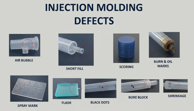
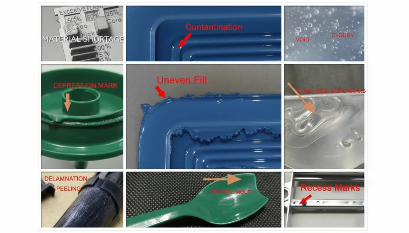
Neste artigo, percorremos os seis defeitos de moldagem de PC mais comuns que encontramos na produção—descoloração e pontos negros, riscas prateadas e bolhas, marcas de fluxo, pontos de material frio e fissuração por tensão interna. Para cada defeito, explicamos o mecanismo físico, como diagnosticá-lo a partir do padrão do defeito e os ajustes específicos de processo e ferramenta que o resolvem. Estas perspetivas provêm de duas décadas de experiência prática em moldagem de PC em aplicações automóveis, médicas e de eletrónica de consumo.

- A sensibilidade à humidade do PC (exige <0.02% de humidade) é a causa raiz da maioria dos defeitos superficiais
- Maior viscosidade de fusão que o ABS ou PP significa que o PC precisa de controlo preciso da temperatura e pressão
- A tensão interna em peças transparentes de PC pode causar fendilhação retardada dias após a moldagem
- A maioria dos defeitos partilha correções comuns: secagem adequada, temperatura do cilindro otimizada e ventilação do molde adequada
- A experiência da fábrica com mais de 400 materiais mostra que apenas a disciplina de secagem elimina 60% dos defeitos em PC
O que Torna a Moldagem por Injeção em Policarbonato Tão Desafiante?
O policarbonato é um dos termoplásticos de engenharia mais difíceis de moldar por injeção. A sua estrutura molecular única—cadeias lineares com anéis de benzeno, grupos isopropilideno e ligações de carbonato—cria três desafios principais de processamento que o distinguem de materiais mais fáceis como o polipropileno ou o ABS.
If you are comparing vendors or planning procurement, our injection molding supplier sourcing guide covers RFQ prep, qualification, and commercial risk checks.
Primeiro, o PC não tem um ponto de fusão definido. Em vez disso, amolece gradualmente numa ampla gama de temperaturas (230–320 °C), o que significa a viscosidade de fusão permanece elevada1 durante o processamento normal. Ao contrário dos polímeros semicristalinos, que se afinam drasticamente acima do seu ponto de fusão, o PC comporta-se mais como um fluido newtoniano — a sua viscosidade é mais sensível a alterações de temperatura do que à taxa de corte. Pequenos desvios de temperatura de apenas 10–15 °C podem levar a massa fundida de processável a degradada.
Em segundo lugar, o PC é extremamente sensível à humidade. Mesmo quantidades vestigiais de água (acima de 0,02% em peso) causam degradação hidrolítica a temperaturas de processamento, quebrando as cadeias poliméricas e reduzindo as propriedades mecânicas. Isto significa que a pré-secagem completa a 120 °C durante 3–4 horas é obrigatória—não opcional. Na nossa experiência de processamento de mais de 400 materiais na fábrica de Xangai, os defeitos relacionados com a humidade representam cerca de 60% de todos os problemas de moldagem de PC que resolvemos.
Na nossa fábrica de Xangai, com mais de 20 anos de experiência em moldagem por injeção em mais de 400 materiais plásticos, vimos todos os padrões de defeitos de PC imagináveis. O controlo da humidade e a disciplina da temperatura do cilindro são as duas variáveis que separam uma produção de PC tranquila de um evento dispendioso de sucata.
Em terceiro lugar, a elevada viscosidade da massa fundida de PC significa que molde de injeção O projeto deve acomodar pressões de injeção mais elevadas, canais e distribuidores maiores e ranhuras de exaustão mais profundas do que o necessário para plásticos comuns. Canais de fluxo subdimensionados criam calor de cisalhamento excessivo, o que paradoxalmente causa degradação térmica mesmo quando as temperaturas do cilindro estão definidas corretamente. Compreender estas três restrições—alta viscosidade, sensibilidade à humidade e sensibilidade ao cisalhamento—é a base para prevenir todos os defeitos abordados neste artigo.

O que Causa Descoloração, Amarelecimento e Pontos Pretos nas Peças de PC?
A descoloração é o defeito visual mais comum na moldagem por injeção de PC, causado pela degradação térmica da massa fundida. A causa raiz é tipicamente temperatura excessiva do cilindro, tempo de residência demasiado longo ou zonas mortas no sistema de plastificação onde o material degradado se acumula e é libertado intermitentemente para o fluxo de massa fundida.
A resina de PC pura tem excelente estabilidade térmica e pode tolerar temperaturas até 300 °C sem decomposição significativa. O problema surge quando os processadores usam misturas de PC modificadas, material reciclado ou PC composto com retardadores de chama e cargas. Estes aditivos reduzem consideravelmente a janela de processamento. Por exemplo, as misturas PC/ABS normalmente requerem temperaturas do cilindro em torno de 250 °C, enquanto as misturas PC/PBT para produtos de iluminação necessitam de aproximadamente 280 °C—cada combinação tem o seu próprio limite térmico que, uma vez excedido, desencadeia amarelecimento ou carbonização irreversíveis.
Os pontos pretos são uma variante particularmente frustrante porque podem aparecer intermitentemente — por vezes duas ou três peças seguidas, depois desaparecendo. Este padrão quase sempre indica material morto preso algures no sistema de plastificação: folgas do anel de retenção da rosca, interfaces da ponta da biqueira ou ranhuras na parede do cilindro. O material preso carboniza com o tempo, depois solta-se em pedaços. Quando os produtos de decomposição do PC se acumulam além de um limiar crítico, também catalisam mais decomposição, criando um efeito em cascata — especialmente grave nos graus retardadores de chama.
| Tipo de Material de PC | Temperatura do Cilindro Recomendada | Risco de Degradação Acima |
|---|---|---|
| PC puro (grau ótico) | 270-300 °C | 320 °C |
| ISO 10993: | 240-260 °C | 280 °C |
| PC com retardador de chama | 230-260 °C | 280 °C |
| Mistura PC/PBT (iluminação) | 260-280 °C | 300 °C |
| PC Reciclado | 240-270 ºC | 290 ºC (variável) |
As correções são sistemáticas. Primeiro, verifique os pontos de ajuste da temperatura do cilindro em relação ao grau do material e reduza as temperaturas das zonas de alimentação e compressão em incrementos de 5–10 °C até que a descoloração pare. Segundo, assegure uma secagem completa: 120 °C durante 3–4 horas usando um secador desumidificador, nunca excedendo 10 horas para evitar o envelhecimento do material. Terceiro, inspecione o sistema de plastificação em busca de zonas mortas—remova e limpe o bico, verifique o anel e a rosca se a massa fundida de tiro a ar apresentar descoloração mesmo a temperaturas corretas. Finalmente, purgue o cilindro com um material termicamente estável (PS ou PE) antes e depois de cada ciclo de produção, e nunca deixe o PC parado à temperatura de processamento durante paragens prolongadas; baixe o cilindro para 160 °C (Transição vítrea do PC2) ou abaixo para paragens térmicas.
“Lowering barrel temperature is always the first step when PC parts show yellowing.”Verdadeiro
Lowering barrel temperature is the correct first response because excessive heat is the most common cause of PC yellowing. However, if discoloration persists after a 10-15 C reduction, the root cause likely shifts to dead material in the plasticizing system or contaminated raw material.
“Using higher back pressure always improves PC melt quality.”Falso
Excessive back pressure generates additional shear heat in the barrel, which can accelerate thermal degradation of PC. The correct approach is moderate back pressure (0.5-1.5 MPa) combined with adequate drying and proper barrel temperature profiling.
Por que Aparecem Estrias Prateadas e Bolhas nos Produtos de PC?
Silver streaks (also called gas streaks) and bubbles are surface and internal defects caused by gas trapped in the melt during cavity filling. In PC injection molding, the four gas sources are water vapor, entrained air, thermal decomposition gas, and solvent gas—water vapor and decomposition gas account for the vast majority of cases.
Silver streaks form when gas dissolved in the pressurized melt escapes to the product surface as cavity pressure drops after filling. The escaping gas leaves tiny elongated bubbles that sparkle under light, always aligned with material flow direction. Bubbles, on the other hand, are gas pockets trapped in the wall thickness—particularly visible in transparent PC parts. Vacuum bubbles are different: they form not from gas but from volumetric shrinkage when insufficient holding pressure leaves a void in thick sections.
How to Diagnose the Gas Source Behind Silver Streaks
Diagnosing which gas is responsible requires reading the defect pattern. Randomly scattered surface bubbles point to water vapor—the most common culprit in PC because the material is so hygroscopic. Fine, dense bubble clusters concentrated near the gate in a radial or fan-shaped pattern indicate entrained air, typically from excessive screw retraction speed or insufficient back pressure. Discoloration accompanying the silver streaks points to decomposition gas from overheated melt. The diagnostic process matters because each gas source requires a different fix.
For moisture-driven silver streaks, the solution is straightforward: ensure drying at 120 °C for 3–4 hours with a dehumidifying dryer. Verify effectiveness by air-shooting—the extruded melt should be continuous, smooth, and free of white vapor. For air entrainment, reduce screw speed, increase back pressure, and extend melt time during the cooling phase. For decomposition gas, lower barrel temperature section by section starting from the nozzle, and check for excessively long residence times (using oversized equipment for small parts is a common culprit).
Vacuum bubbles require a different approach because they are a shrinkage phenomenon, not a gas issue. Increase holding pressure and extend holding time to pack more material into the thick section. Position the gate at the thickest wall to ensure pressure transmission. Increase mold temperature locally at the void location to slow solidification and allow shrinkage compensation. For transparent products, post-mold slow cooling in hot water can also reduce vacuum bubble formation.
“Post-molding heat treatment at 120 C for 2 hours can significantly reduce internal stress in PC parts.”Verdadeiro
Heat treatment at approximately 120 C allows PC molecular chain segments to regain mobility and relax frozen elastic deformation. Oriented molecules return toward a random state, reducing both orientation and temperature stress. This is standard practice for optical and stress-critical PC applications.
“Vacuum bubbles in PC parts are caused by trapped air.”Falso
Vacuum bubbles are actually caused by volumetric shrinkage during cooling, not trapped air. When holding pressure is insufficient or the gate freezes too early, the still-molten core shrinks away from the already-solidified skin, creating a void. The fix is increased holding pressure and time, not venting.
O que São Marcas de Impressão Digital e Linhas de Turbulência — e Como as Corrige?
Fingerprint marks and turbulence lines are flow defects caused by PC melt viscosity being too high relative to injection speed and mold temperature. The melt fills the cavity in a stick-slip pattern, leaving wavy lines perpendicular to flow direction (fingerprints) or radial streaks near the gate (turbulence).
Fingerprint marks develop when injection speed and pressure are too low for the melt viscosity. The front of the melt stream contacts the cold mold wall, solidifies, and shrinks. The hot melt behind it pushes the shrunken skin forward, then that layer also cools and shrinks. This alternating advance-freeze cycle creates the characteristic wavy pattern that looks like a human fingerprint. The effect is most visible on large, flat PC surfaces—think display covers or control panels.
Turbulence marks are related but distinct. They appear as irregular flow lines radiating from the gate, caused by the melt hitting the cavity wall at high velocity and skidding across the cold surface before stabilizing into laminar flow. This defect is particularly common when gate design creates a sharp velocity transition—such as a small gate feeding into a large, thick cavity. The key distinction: fingerprints run perpendicular to flow, while turbulence lines run parallel.
Both defects share the same solution set. Increase the nozzle and front barrel temperatures to reduce melt viscosity—this is the single most effective adjustment. Raise mold temperature, especially at the location where marks appear; for appearance-critical PC parts, a mold temperature controller set to 100–120 °C is standard practice. Increase injection speed to shift the filling pattern from stick-slip to continuous flow; multi-stage injection allows you to adjust speed section by section, targeting the problem area without causing flash elsewhere. On the mold side, enlarge gates and runners to reduce flow resistance, and ensure adequate venting and cold-slug wells.
With 47 injection machines ranging from 90T to 1850T, and MOLDFLOW simulation for gate and runner optimization, we typically resolve flow mark issues during the DFM stage—before steel is ever cut. Simulation catches the velocity transitions that cause turbulence marks, allowing gate redesign before tooling.
Como se Formam as Manchas de Material Frio e como as Pode Prevenir?
Cold material spots are foggy, bright, or worm-shaped marks near the gate caused by partially solidified melt entering the cavity. They form when the melt front loses too much heat at the nozzle tip, runner, or gate before cavity filling begins—or when excessive holding pressure forces already-cooled runner material into the part.
There are two distinct mechanisms. The first is forward cold material: the melt at the nozzle tip and runner entrance cools between shots because the nozzle contacts the cold mold plate. When injection begins, this chilled material enters the cavity first. On thin-walled parts, it spreads into smoky or paste-like cloudy patches. On thick-walled parts, it forms a curved scar resembling an earthworm. The second mechanism is back-pressure cold material: excessive holding time and pressure squeeze already-cooled material from the runner and gate into the part, creating a small circular bright spot near the gate.
Prevention is straightforward but requires attention to detail. Install a cold-slug well at the end of each runner—this traps the forward cold material before it enters the cavity. Increase nozzle temperature to reduce heat loss at the tip. Increase mold temperature to narrow the gap between melt and mold surface temperatures. Reduce injection speed at the start of filling to avoid melt fracture at the gate, then increase speed for the main fill. Optimize gate position, size, and shape to avoid sharp velocity transitions. For holding-pressure cold spots, shorten holding time and reduce holding pressure to the minimum needed for dimensional stability. Also ensure thorough material drying—residual moisture in the cold-slug can worsen the visual defect.
Por Que é que a Tensão Interna Fissura Produtos de PC Transparentes?
Internal stress in PC products is frozen-in molecular orientation and uneven cooling stress. It can cause warpage, reduced optical clarity, and delayed stress cracking days or weeks after molding—transparent PC parts are the canary in the coal mine.
Two primary mechanisms create internal stress. Orientation stress comes from polymer chains being stretched during flow and then frozen in place before they can relax back to a random coil configuration. Higher injection pressure, faster injection speed, and longer holding time all increase orientation by applying more shear to the melt. Temperature stress comes from the large temperature differential between the hot melt core and the cold mold wall. Because PC has high specific heat capacity and low thermal conductivity, the surface solidifies long before the interior—creating compressive stress on the outside and tensile stress on the inside.
The practical consequence is that a PC part may look perfect immediately after molding but develop micro-cracks within days, especially when exposed to organic solvents (cleaning agents, adhesives) or elevated temperatures. In our production environment, we have seen transparent PC lenses crack during assembly simply because the operator used an alcohol-based cleaning wipe—the internal stress was already at the failure threshold, and the solvent lowered it just enough to initiate cracking.
Our in-house mold manufacturing facility (100+ mold sets per month) allows us to optimize gate placement, runner geometry, and cooling channel layout specifically for stress-sensitive PC parts. Combined with ISO 9001 and ISO 13485 quality systems, we catch internal stress issues during first-article inspection using polarized light analysis.
“Polarized light analysis can detect internal stress in transparent PC parts before they crack.”Verdadeiro
Under polarized light, stressed PC exhibits birefringence patterns that reveal frozen molecular orientation and uneven cooling stress. This non-destructive inspection method allows factories to catch stress issues during first-article inspection, long before parts fail in service.
“Post-mold annealing at 120 C reduces internal stress in transparent PC parts.”Falso
Annealing at 120 C does indeed reduce internal stress by allowing molecular chains to relax. However, it is not a substitute for proper molding parameters—it can only reduce stress that was created, not eliminate it entirely. The most effective approach is to minimize stress during molding through correct temperature and pressure settings, then use annealing as a final quality assurance step for critical components.
Reducing internal stress requires a holistic approach. Increase melt temperature to reduce viscosity and orientation during flow. Increase mold temperature to allow slower, more uniform cooling and give oriented molecules time to relax. Reduce injection pressure to the minimum needed for complete filling. Minimize holding time—over-packing is a major contributor to orientation stress. Use variable-speed injection: fast fill to avoid flow defects, then slow speed for holding to reduce molecular alignment. For parts with metal inserts, preheat inserts to approximately 200 °C to reduce the thermal mismatch. Finally, post-mold heat treatment at 120 °C for approximately 2 hours allows chain segments to regain mobility and relax frozen deformation—this is standard practice for optical-grade PC components.
“Reducing injection pressure to the minimum needed for cavity filling helps prevent internal stress in PC parts.”Verdadeiro
Excessive injection pressure increases molecular orientation and shear stress, which increases internal stress and the risk of warpage and stress cracking. The minimum pressure that achieves complete filling, combined with adequate melt temperature, produces the lowest-stress PC parts.
“Increasing mold temperature above 100 °C always improves the surface finish of PC parts.”Falso
While higher mold temperature can reduce flow marks and improve surface gloss, exceeding 100 °C for extended cycles can cause excessively long cooling times and lead to thermal degradation of the PC resin near the gate. The optimal mold temperature range for PC is typically 80–100 °C, balancing finish quality with cycle efficiency and part stability.
Que Parâmetros de Processo Deve Monitorizar para Minimizar Defeitos em PC?
There are six parameters that matter most for PC defect prevention: drying, barrel temperature, injection speed, hold pressure, and mold temperature. Getting these right eliminates the vast majority of discoloration, silver streaks, bubbles, flow marks, and internal stress issues.
Drying is non-negotiable. PC requires moisture content below 0.02%3—achieved by dehumidifying dryer at 120 °C for 3–4 hours. Drying beyond 10 hours risks material degradation, especially for flame-retardant grades. Verify drying effectiveness by air-shot inspection before starting production. This single step prevents most silver streaks and surface bubbles.
Barrel temperature must be set as a profile, not a single number. For pure PC, a typical profile runs 250 °C (feed) → 270 °C (compression) → 285 °C (metering) → 290 °C (nozzle). Each modified grade has its own window—PC/ABS at roughly 20 °C lower, PC/PBT at similar or slightly higher temperatures. The key is to start at the lower end of the recommended range and increase only if flow marks or short shots appear. Never set all zones to the same temperature; a proper gradient ensures gradual plasticization without premature melting in the feed zone (which blocks air escape) or under-preheating (which traps air in the melt).
| Parâmetro | Recommended Range (Pure PC) | Defects Prevented |
|---|---|---|
| Drying temperature | 120 C, 3-4 h, dehumidified | Silver streaks, surface bubbles |
| Barrel temperature (nozzle) | 280-295 C | Short shots, flow marks |
| Temperatura do molde | 80-120 ºC | Marcas de impressões digitais, tensão interna |
| Velocidade de injeção | Multi-estágio: enchimento rápido, embalagem lenta | marcas de turbulência, sobre-embalamento |
| Pressão de retenção | 60-80% da pressão de injeção | bolhas de vácuo, marcas de encolhimento |
| Tempo de retenção | Até ao congelamento do canal de alimentação (3-8 s) | vazios por retração, deriva dimensional |
O tempo de residência do fundido merece atenção especial. Utilizar equipamento de grande dimensão para pequenas peças de PC é um erro comum — a grande relação entre o peso do disparo e a capacidade do cilindro significa que o material permanece à temperatura de processamento durante demasiado tempo, acumulando danos térmicos. Como regra geral, o peso do disparo deve ser pelo menos 30–40% da capacidade do cilindro. Se tiver de produzir peças pequenas em máquinas grandes, utilize um parafuso de diâmetro menor ou aceite que purgas frequentes e mudanças de cor são inevitáveis. Finalmente, a temperatura do molde é mais importante para o PC do que para a maioria dos plásticos. Trabalhar com moldes frios (abaixo de 80 °C) acelera a solidificação da superfície, aumenta o stress interno e amplifica as marcas de fluxo. Para peças transparentes ou críticas em termos de aparência, uma temperatura do molde de 100–120 °C com um controlador de temperatura é o padrão da indústria.
Quais São as Perguntas Mais Comuns Sobre Defeitos na Moldagem por Injeção de PC?
Perguntas mais frequentes
Qual é a temperatura de secagem ideal para policarbonato antes da moldagem por injeção?
O policarbonato deve ser seco a 120 °C utilizando um secador desumidificador durante 3 a 4 horas para obter um teor de humidade inferior a 0,02% antes da moldagem por injeção. Este é um requisito não negociável para o processamento bem-sucedido do PC — omitir ou encurtar a etapa de secagem é a causa mais comum de defeitos superficiais. A secagem além de 10 horas arrisca a degradação do material, especialmente para graus retardadores de chama que são mais sensíveis termicamente. Verifique sempre a eficácia com um teste de tiro de ar antes do início da produção — o fundido extrudido deve ser contínuo, liso e livre de vapor branco. Utilizar um secador de funil padrão sem desumidificação é insuficiente para o PC.
O que causa manchas pretas em peças moldadas por injeção de policarbonato?
Manchas pretas em peças moldadas por injeção de PC são tipicamente causadas por material carbonizado preso em zonas mortas do sistema de plastificação — como folgas do anel de retenção da rosca, interfaces da ponta da boquilha ou ranhuras na parede do cilindro. O material preso degrada-se ao longo do tempo e liberta-se intermitentemente para o fluxo de fundido, produzindo manchas escuras que aparecem aleatoriamente em várias peças e depois desaparecem. A desmontagem e limpeza regular do sistema de plastificação, combinada com procedimentos adequados de purga do cilindro usando PS ou PE antes e depois de cada corrida de produção, previne eficazmente este problema. Nunca deixe o material de PC parado à temperatura de processamento durante paragens prolongadas da máquina.
Qual é a temperatura recomendada para moldagem por injeção de policarbonato?
Para policarbonato puro, o perfil de temperatura recomendado do cilindro é de 250 °C (zona de alimentação) a 285-295 °C (boquilha), com temperatura do molde a 80-120 °C. A chave é utilizar um gradiente de temperatura entre as zonas em vez de um único ponto de ajuste, garantindo uma plastificação gradual sem fusão prematura na zona de alimentação. Os graus modificados têm janelas diferentes: as misturas PC/ABS funcionam aproximadamente 20 °C mais baixas, enquanto as misturas PC/PBT podem requerer temperaturas semelhantes ou ligeiramente superiores. Comece sempre no extremo inferior da gama recomendada e aumente apenas se aparecerem defeitos de fluxo.
Como se evita o stress interno em produtos transparentes de PC?
A prevenção de tensões internas em peças transparentes de PC requer uma abordagem multifacetada. Utilize uma temperatura de fusão mais elevada para reduzir a viscosidade e a orientação molecular durante o fluxo. Aumente a temperatura do molde para 100-120 °C para um arrefecimento mais lento e uniforme, permitindo que as moléculas orientadas tenham tempo para relaxar. Minimize a pressão de injeção e de retenção ao mínimo necessário para um preenchimento completo. Utilize injeção de velocidade variável com enchimento rápido seguido de embalagem lenta. O tratamento térmico pós-molde a 120 °C durante aproximadamente 2 horas é uma prática padrão para componentes de grau ótico, para relaxar a orientação molecular congelada.
Por que aparecem riscos prateados em peças moldadas por injeção de PC?
Riscos prateados em peças de PC são causados pela fuga de gás para a superfície do produto durante ou após o enchimento da cavidade, deixando pequenas bolhas alongadas que brilham sob a luz. A fonte de gás mais comum é o vapor de água do material secado de forma inadequada — isto representa a maioria dos casos. O gás de decomposição térmica devido à temperatura excessiva do cilindro é a segunda causa mais comum. Riscos prateados finos e densos concentrados perto do ponto de injeção num padrão radial indicam ar arrastado devido à velocidade excessiva do parafuso ou pressão de retorno insuficiente. A secagem adequada a 120 °C durante 3-4 horas elimina a maioria dos casos causados por humidade.
Os defeitos de moldagem por injeção de policarbonato podem ser corrigidos ajustando apenas os parâmetros da máquina?
Muitos defeitos do PC — particularmente estrias prateadas, descoloração e marcas de fluxo — podem ser resolvidos apenas através de ajustes dos parâmetros da máquina, principalmente condições de secagem, perfil de temperatura do cilindro e otimização da velocidade de injeção. No entanto, defeitos recorrentes como manchas persistentes de material frio ou marcas de turbulência frequentemente requerem modificações no molde, como alargamento de canais de alimentação, canais de ventilação adicionais ou poços de massa fria. A redução da tensão interna também pode exigir alterações de design para uniformidade da espessura da parede e pré-aquecimento de insertos. A abordagem mais eficaz combina a otimização de parâmetros com um design adequado do molde desde o início.
Qual é a diferença entre bolhas e bolhas de vácuo em peças de PC?
Bolhas em peças de PC são vazios preenchidos com gás causados por vapor de água, ar arrastado ou gás de decomposição térmica aprisionado durante o enchimento da cavidade. Estão presentes imediatamente após a abertura do molde e não crescem ao longo do tempo. As bolhas de vácuo são fundamentalmente diferentes — são vazios induzidos por contração que se formam durante o arrefecimento quando a pressão de retenção é insuficiente para compensar a contração volumétrica em secções espessas. As bolhas de vácuo podem aparecer ou aumentar após a desmoldagem à medida que o interior continua a arrefecer e a contrair. A diferença de diagnóstico determina se se aborda o teor de gás através da secagem e temperatura, ou a compactação através da pressão de retenção.
Como Pode Obter Apoio Especializado para o Seu Projeto de Moldagem por Injeção em PC?
A ZetarMold é o parceiro de fabrico para projetos de moldagem por injeção de policarbonato que exigem zero defeitos. A nossa equipa de engenharia traz mais de 20 anos de experiência no processamento de PC e mais de 400 materiais para cada projeto, desde a secagem do material e o perfil de temperatura até ao design do ponto de injeção e alívio de tensões. As nossas instalações internas de ferramentaria, capacidade de simulação MOLDFLOW e sistemas de qualidade certificados ISO significam que as suas peças de PC são projetadas para qualidade desde a fase de DFM em diante.
Precisa de um orçamento para o seu projeto de moldagem por injeção de policarbonato? Obtenha preços competitivos, feedback de DFM e cronograma de produção da nossa equipa de engenharia. Solicite um Orçamento Gratuito hoje, ou explore os nossos Injection Molding Complete Guide para uma visão geral abrangente do processo.
-
a viscosidade de fusão permanece elevada: a viscosidade do fundido permanece elevada refere-se a que a viscosidade do fundido de PC é mais sensível a alterações de temperatura do que à taxa de corte, comportando-se de forma semelhante a um fluido newtoniano durante o processamento. ↩
-
Transição vítrea do PC: A transição vítrea do PC refere-se ao facto de o policarbonato ter uma temperatura de transição vítrea (Tg) de aproximadamente 147-150 °C, que determina a temperatura mínima de retenção térmica. ↩
-
moisture content below 0.02%: teor de humidade abaixo de 0,02% refere-se a que o PC requer um teor de humidade abaixo de 0,02% (200 ppm) antes do processamento para prevenir a degradação hidrolítica às temperaturas de moldagem. ↩


