Poliwęglan (PC) jest jednym z najbardziej wszechstronnych termoplastów konstrukcyjnych stosowanych w formowaniu wtryskowym — jest przezroczysty, odporny na uderzenia i stabilny termicznie. Każdy, kto prowadził produkcję z PC, wie jednak, że jest to także jeden z najbardziej kapryśnych materiałów w przetwórstwie. Wysoka lepkość stopu, skrajna wrażliwość na wilgoć i skłonność do kumulowania naprężeń wewnętrznych sprawiają, że nawet niewielkie odchylenia procesu mogą powodować widoczne wady: przebarwienia, srebrne smugi, pęcherze, ślady płynięcia i pęknięcia naprężeniowe.
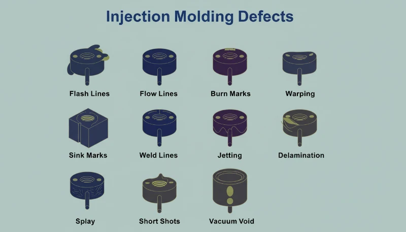
W tym artykule omawiamy sześć najczęstszych wad formowania PC, z którymi spotykamy się w produkcji: przebarwienia i czarne punkty, srebrne smugi i pęcherze, smugi przepływu, plamy zimnego tworzywa oraz pękanie pod wpływem naprężeń wewnętrznych. W przypadku każdej wady wyjaśniamy mechanizm fizyczny, sposób jej diagnozowania na podstawie obrazu wady oraz konkretne korekty procesu i oprzyrządowania, które pozwalają ją usunąć. Wnioski te wynikają z dwóch dekad praktycznego doświadczenia w formowaniu PC dla branży motoryzacyjnej, medycznej i elektroniki użytkowej.
- Wrażliwość PC na wilgoć (wymagana wilgotność <0.02%) jest główną przyczyną większości wad powierzchni
- Większa lepkość stopionego tworzywa niż w przypadku ABS lub PP oznacza, że PC wymaga precyzyjnej kontroli temperatury i ciśnienia
- Naprężenia wewnętrzne w przezroczystych częściach z PC mogą powodować opóźnione pękanie kilka dni po formowaniu
- Większość wad można usunąć tymi samymi metodami: prawidłowym suszeniem, optymalizacją temperatury cylindra i odpowiednim odpowietrzeniem formy
- Doświadczenie z ponad 400 materiałami pokazuje, że sama dyscyplina suszenia eliminuje 60% wad PC
Dlaczego formowanie wtryskowe poliwęglanu jest tak wymagające?
Poliwęglan jest jednym z najtrudniejszych w przetwórstwie wtryskowym termoplastów konstrukcyjnych. Jego unikalna budowa cząsteczkowa — liniowe łańcuchy zawierające pierścienie benzenowe, grupy izopropylidenowe i wiązania węglanowe — stwarza trzy podstawowe wyzwania procesowe, które odróżniają go od łatwiejszych w przetwórstwie materiałów, takich jak polipropylen czy ABS.
Jeśli porównujesz dostawców lub planujesz zakupy, nasz przewodnik po pozyskiwaniu dostawców usług formowania wtryskowego omawia przygotowanie zapytania ofertowego, kwalifikację i kontrolę ryzyka handlowego.
Po pierwsze, PC nie ma wyraźnej temperatury topnienia. Zamiast tego stopniowo mięknie w szerokim zakresie temperatur (230–320 °C), przez co podczas normalnego przetwarzania lepkość stopu pozostaje wysoka1. W przeciwieństwie do polimerów półkrystalicznych, które powyżej temperatury topnienia gwałtownie tracą lepkość, PC zachowuje się bardziej jak ciecz newtonowska — jego lepkość jest bardziej wrażliwa na zmianę temperatury niż szybkość ścinania. Odchylenie o zaledwie 10–15 °C może zmienić stop z przetwarzalnego w zdegradowany.
Po drugie, PC jest wyjątkowo wrażliwy na wilgoć. Nawet śladowa ilość wody (powyżej 0.02% masy) powoduje w temperaturze przetwarzania degradację hydrolityczną, rozrywając łańcuchy polimeru i pogarszając właściwości mechaniczne. Dlatego dokładne suszenie wstępne w 120 °C przez 3–4 godziny jest obowiązkowe, a nie opcjonalne. Z naszego doświadczenia z ponad 400 materiałami w zakładzie w Szanghaju wynika, że wady związane z wilgocią stanowią około 60% wszystkich diagnozowanych problemów z formowaniem PC.
W naszej fabryce w Szanghaju, dysponującej ponad 20-letnim doświadczeniem w formowaniu wtryskowym przeszło 400 tworzyw sztucznych, zetknęliśmy się z każdym możliwym rodzajem wad PC. Kontrola wilgotności i rygorystyczne utrzymywanie temperatury cylindra to dwie zmienne, które odróżniają stabilną produkcję PC od kosztownej partii braków.
Po trzecie, wysoka lepkość stopionego PC oznacza, że konstrukcja formy wtryskowej musi uwzględniać wyższe ciśnienia wtrysku, większe przewężki i kanały wlewowe oraz głębsze rowki odpowietrzające niż w przypadku popularnych tworzyw. Zbyt małe kanały przepływowe wytwarzają nadmierne ciepło ścinania, które paradoksalnie powoduje degradację termiczną nawet przy prawidłowej temperaturze cylindra. Zrozumienie tych trzech ograniczeń — wysokiej lepkości, wrażliwości na wilgoć i wrażliwości na ścinanie — jest podstawą zapobiegania wszystkim wadom opisanym w tym artykule.
Co powoduje przebarwienia, żółknięcie i czarne plamy na częściach z PC?
Przebarwienia są najczęstszą wadą wizualną w formowaniu wtryskowym PC i wynikają z degradacji termicznej stopu. Ich podstawową przyczyną jest zazwyczaj zbyt wysoka temperatura cylindra, nadmiernie długi czas przebywania materiału lub martwe strefy w układzie uplastyczniającym, w których zdegradowany materiał gromadzi się, a następnie okresowo trafia do strumienia stopu.
Czysta żywica PC ma doskonałą stabilność termiczną i może wytrzymać temperatury do 300 °C bez znacznego rozkładu. Problem pojawia się, gdy przetwórcy stosują modyfikowane mieszanki PC, materiał z recyklingu albo PC z dodatkiem środków uniepalniających i napełniaczy. Dodatki te znacząco zawężają okno przetwórcze. Na przykład mieszanki PC/ABS wymagają zazwyczaj temperatury cylindra około 250 °C, natomiast mieszanki PC/PBT do produktów oświetleniowych potrzebują około 280 °C — każda kombinacja ma własną górną granicę termiczną, której przekroczenie powoduje nieodwracalne żółknięcie lub zwęglenie.
Czarne wtrącenia są szczególnie uciążliwą odmianą wady, ponieważ mogą pojawiać się sporadycznie — czasem w dwóch lub trzech kolejnych wtryskach, po czym znikają. Taki wzorzec niemal zawsze wskazuje na zaleganie materiału w martwej strefie układu uplastyczniającego: w szczelinach pierścienia zwrotnego ślimaka, na styku końcówki dyszy albo w rysach na ściance cylindra. Uwięziony materiał z czasem ulega zwęgleniu, a następnie odrywa się w postaci grudek. Gdy produkty rozkładu PC przekroczą stężenie krytyczne, dodatkowo katalizują dalszy rozkład, wywołując efekt kaskadowy — szczególnie silny w gatunkach trudnopalnych.
| Rodzaj materiału PC | Zalecana temperatura cylindra | Ryzyko degradacji powyżej |
|---|---|---|
| Czysty PC (gatunek optyczny) | 270-300 C | 320 C |
| Mieszanka PC/ABS | 240-260 C | 280 C |
| PC ze środkiem uniepalniającym | 230-260 C | 280 C |
| Mieszanka PC/PBT (oświetlenie) | 260-280 C | 300 C |
| PC z recyklingu | 240-270 C | 290 C (wartość zmienna) |
Rozwiązania są systematyczne. Najpierw sprawdź nastawy temperatury cylindra względem gatunku materiału i obniżaj temperaturę strefy zasilania i sprężania co 5–10 °C, aż przebarwienia ustąpią. Następnie zapewnij dokładne suszenie: 120 °C przez 3–4 godziny w suszarce osuszającej, nigdy dłużej niż 10 godzin, aby uniknąć starzenia materiału. Potem sprawdź układ uplastyczniający pod kątem stref martwych — wymontuj i wyczyść dyszę, pierścień zwrotny oraz ślimak, jeśli stop wypuszczony swobodnie przebarwia się mimo prawidłowej temperatury. Na koniec przed i po każdej serii produkcyjnej przepłucz cylinder materiałem stabilnym termicznie (PS lub PE) i podczas dłuższych przestojów nigdy nie pozostawiaj PC w temperaturze przetwarzania; przy podtrzymaniu cieplnym obniż temperaturę cylindra do 160 °C (temperatura zeszklenia PC2) lub niżej.
„Obniżenie temperatury cylindra jest zawsze pierwszym działaniem, gdy części z PC żółkną”.True
Obniżenie temperatury cylindra jest właściwą pierwszą reakcją, ponieważ nadmierna temperatura jest najczęstszą przyczyną żółknięcia PC. Jeśli jednak przebarwienie utrzymuje się po obniżeniu temperatury o 10-15 C, przyczyną jest prawdopodobnie zalegający materiał w układzie uplastyczniającym lub zanieczyszczony surowiec.
„Wyższe przeciwciśnienie zawsze poprawia jakość stopionego PC”.False
Nadmierne ciśnienie wsteczne wytwarza w cylindrze dodatkowe ciepło wskutek ścinania, co może przyspieszyć degradację termiczną PC. Prawidłowe podejście polega na zastosowaniu umiarkowanego ciśnienia wstecznego (0.5-1.5 MPa), odpowiednim wysuszeniu materiału i właściwym profilu temperatury cylindra.
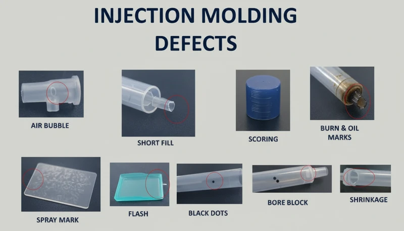
Dlaczego na wyrobach z PC pojawiają się srebrne smugi i pęcherze?
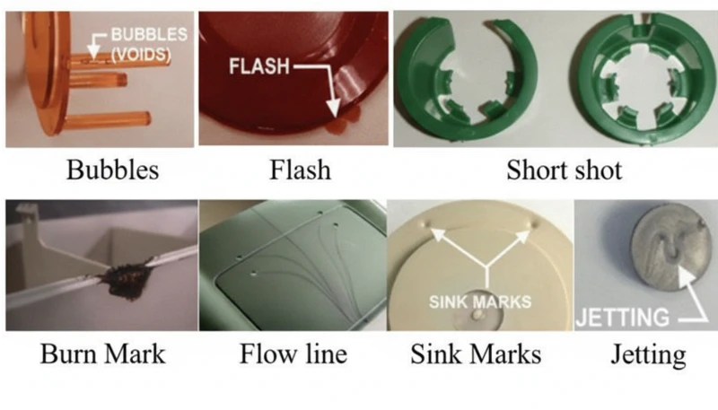
Srebrzyste smugi (nazywane również smugami gazowymi) oraz pęcherze to wady powierzchniowe i wewnętrzne spowodowane gazem uwięzionym w stopie podczas wypełniania gniazda. W formowaniu wtryskowym PC występują cztery źródła gazu: para wodna, powietrze zawleczone, gazy z rozkładu termicznego i pary rozpuszczalników — zdecydowana większość przypadków wynika z pary wodnej i gazów rozkładowych.
Srebrne smugi powstają, gdy gaz rozpuszczony w stopionym tworzywie pod ciśnieniem wydostaje się na powierzchnię wyrobu wskutek spadku ciśnienia w gnieździe po napełnieniu. Ulatniający się gaz pozostawia drobne, wydłużone pęcherzyki, które połyskują w świetle i są zawsze ułożone zgodnie z kierunkiem płynięcia materiału. Z kolei pęcherze to kieszenie gazowe uwięzione w grubości ścianki — szczególnie widoczne w przezroczystych detalach z PC. Pęcherze próżniowe mają inne pochodzenie: powstają nie z gazu, lecz wskutek skurczu objętościowego, gdy niewystarczające ciśnienie podtrzymania pozostawia pustkę w grubych przekrojach.
Jak zdiagnozować źródło gazu powodującego smugi srebrne?
Ustalenie, który gaz odpowiada za wadę, wymaga analizy jej wzoru. Losowo rozmieszczone pęcherzyki powierzchniowe wskazują na parę wodną — najczęstszą przyczynę w przypadku PC, ponieważ materiał ten jest silnie higroskopijny. Drobne, gęste skupiska pęcherzyków skoncentrowane w pobliżu przewężki i układające się promieniście lub wachlarzowo wskazują na uwięzione powietrze, zwykle wskutek nadmiernej prędkości wycofywania ślimaka albo niewystarczającego przeciwciśnienia. Przebarwienia towarzyszące srebrnym smugom wskazują na gaz powstający podczas rozkładu przegrzanego stopu. Proces diagnostyczny ma znaczenie, ponieważ każde źródło gazu wymaga innego działania korygującego.
W przypadku srebrnych smug spowodowanych wilgocią rozwiązanie jest proste: materiał należy suszyć w temperaturze 120 °C przez 3–4 godziny w osuszaczu z powietrzem odwilżonym. Skuteczność należy sprawdzić przez swobodny wtrysk — wypływające tworzywo powinno tworzyć ciągłe, gładkie pasmo bez białej pary. W razie porywania powietrza należy zmniejszyć prędkość obrotową ślimaka, zwiększyć przeciwciśnienie i wydłużyć czas uplastyczniania podczas fazy chłodzenia. W przypadku gazów rozkładowych należy stopniowo obniżać temperaturę poszczególnych stref cylindra, zaczynając od dyszy, oraz sprawdzić, czy czas przebywania tworzywa nie jest zbyt długi (częstą przyczyną jest użycie zbyt dużej maszyny do małych części).
Pęcherze próżniowe wymagają innego podejścia, ponieważ wynikają ze skurczu, a nie z obecności gazu. Należy zwiększyć ciśnienie docisku i wydłużyć czas docisku, aby wprowadzić więcej materiału do grubej sekcji. Punkt wtrysku należy umieścić przy najgrubszej ściance, aby zapewnić przenoszenie ciśnienia. Miejscowo, w obszarze powstawania pustki, należy podnieść temperaturę formy, aby spowolnić krzepnięcie i umożliwić kompensację skurczu. W przypadku wyrobów przezroczystych powolne chłodzenie po wyjęciu z formy w gorącej wodzie może również ograniczyć powstawanie pęcherzy próżniowych.
"Obróbka cieplna po formowaniu w temperaturze 120 C przez 2 godziny może znacznie zmniejszyć naprężenia wewnętrzne w detalach z PC."True
Obróbka cieplna w temperaturze około 120 C umożliwia segmentom łańcuchów molekularnych PC odzyskanie ruchliwości i odprężenie zamrożonych odkształceń sprężystych. Zorientowane cząsteczki powracają do stanu losowego, zmniejszając naprężenia orientacyjne i termiczne. Jest to standardowa praktyka w zastosowaniach optycznych i innych zastosowaniach PC krytycznych pod względem naprężeń.
"Pęcherze próżniowe w częściach z PC są spowodowane uwięzionym powietrzem."False
Pęcherze próżniowe powstają w rzeczywistości wskutek skurczu objętościowego podczas chłodzenia, a nie przez uwięzione powietrze. Gdy ciśnienie docisku jest zbyt niskie lub przewężka zamarza zbyt wcześnie, wciąż stopiony rdzeń kurczy się i oddziela od zestalonej już warstwy zewnętrznej, tworząc pustkę. Rozwiązaniem jest zwiększenie ciśnienia i czasu docisku, a nie poprawa odpowietrzania.
Czym są ślady palcowe i linie turbulencji — oraz jak je usunąć?
Ślady przypominające odciski palców i linie turbulencji to wady przepływu wynikające ze zbyt dużej lepkości stopionego PC względem prędkości wtrysku i temperatury formy. Stop wypełnia gniazdo skokowo, pozostawiając faliste linie prostopadłe do kierunku przepływu lub promieniste smugi przy przewężce.
Ślady linii papilarnych powstają, gdy prędkość i ciśnienie są za niskie dla lepkości stopu. Czoło strugi styka się z zimną ścianką, krzepnie i kurczy, a gorący stop pcha tę warstwę; cykl się powtarza, tworząc falisty wzór. Efekt jest najbardziej widoczny na dużych płaskich powierzchniach PC, np. osłonach wyświetlaczy.
Ślady turbulencji są wadą powiązaną, lecz odrębną. Mają postać nieregularnych linii płynięcia rozchodzących się promieniście od przewężki. Powstają, gdy stopione tworzywo z dużą prędkością uderza w ściankę gniazda i ślizga się po zimnej powierzchni, zanim przepływ ustabilizuje się i stanie laminarny. Wada ta występuje szczególnie często, gdy konstrukcja przewężki powoduje gwałtowną zmianę prędkości — na przykład gdy mała przewężka zasila duże, grube gniazdo. Kluczowa różnica: ślady przypominające odciski palców biegną prostopadle do kierunku przepływu, natomiast linie turbulencji — równolegle.
Obie wady mają ten sam zestaw rozwiązań. Zwiększ temperaturę dyszy i przedniej strefy cylindra, aby obniżyć lepkość stopu — jest to najskuteczniejsza pojedyncza regulacja. Podnieś temperaturę formy, zwłaszcza w miejscu występowania śladów; w przypadku części PC o krytycznym wyglądzie standardową praktyką jest sterownik temperatury formy ustawiony na 100–120 °C. Zwiększ prędkość wtrysku, aby przejść od skokowego do ciągłego wzorca wypełniania; wtrysk wielostopniowy pozwala regulować prędkość odcinek po odcinku, eliminując problematyczny obszar bez powodowania wypływek w innych miejscach. Po stronie formy powiększ przewężki i kanały, aby zmniejszyć opory przepływu, oraz zapewnij odpowiednie odpowietrzenie i studzienki zimnego materiału.
Dysponując 47 wtryskarkami o sile zwarcia od 90T do 1850T oraz symulacją MOLDFLOW do optymalizacji przewężek i kanałów wlewowych, problemy ze smugami płynięcia rozwiązujemy zwykle na etapie DFM — jeszcze przed rozpoczęciem obróbki stali. Symulacja wykrywa zmiany prędkości powodujące ślady turbulencji, co pozwala przeprojektować przewężkę przed wykonaniem oprzyrządowania.
Jak powstają ślady zimnego materiału i jak im zapobiegać?
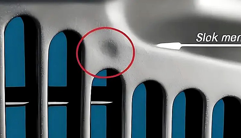
Plamy zimnego tworzywa to mętne, błyszczące lub robakowate ślady w pobliżu przewężki, powstające wskutek przedostania się do gniazda częściowo zestalonego tworzywa. Tworzą się, gdy czoło strugi traci zbyt dużo ciepła na końcówce dyszy, w kanale doprowadzającym lub przewężce, zanim rozpocznie się wypełnianie gniazda, albo gdy nadmierne ciśnienie docisku wtłacza do wypraski schłodzone już tworzywo z kanału.
Występują dwa odrębne mechanizmy. Pierwszy to zimny materiał przemieszczający się do przodu: tworzywo na końcu dyszy i przy wejściu do kanału wlewowego stygnie między cyklami, ponieważ dysza styka się z zimną płytą formy. Po rozpoczęciu wtrysku schłodzony materiał jako pierwszy trafia do gniazda. W częściach cienkościennych rozpływa się, tworząc dymne lub pastowate, mętne plamy. W częściach grubościennych tworzy zakrzywioną bliznę przypominającą dżdżownicę. Drugi mechanizm to zimny materiał wywołany przeciwciśnieniem: zbyt długi czas docisku i nadmierne ciśnienie wtłaczają do części schłodzony już materiał z kanału wlewowego i przewężki, tworząc niewielką, okrągłą, błyszczącą plamkę w pobliżu przewężki.
Zapobieganie jest proste, ale wymaga dbałości o szczegóły. Na końcu każdego kanału wlewowego wykonaj studzienkę zimnego czopa — zatrzyma ona czołową porcję wychłodzonego materiału, zanim trafi on do gniazda. Podnieś temperaturę dyszy, aby ograniczyć straty ciepła na jej końcówce. Podnieś temperaturę formy, aby zmniejszyć różnicę między temperaturą stopionego tworzywa a powierzchnią formy. Zmniejsz prędkość wtrysku na początku napełniania, aby uniknąć pękania strugi przy przewężce, a następnie zwiększ ją podczas zasadniczego napełniania. Zoptymalizuj położenie, wielkość i kształt przewężki, aby uniknąć gwałtownych zmian prędkości. W przypadku zimnych plam związanych z dociskiem skróć czas docisku i zmniejsz jego ciśnienie do minimum wymaganego dla stabilności wymiarowej. Zadbaj również o dokładne wysuszenie materiału — wilgoć resztkowa w zimnym czopie może nasilić wadę wizualną.
Dlaczego naprężenia wewnętrzne powodują pękanie przezroczystych wyrobów z PC?
Naprężenia wewnętrzne w wyrobach z PC wynikają z utrwalonej orientacji cząsteczek i nierównomiernych naprężeń chłodzenia. Mogą powodować odkształcenia, pogorszenie przejrzystości optycznej oraz opóźnione pękanie naprężeniowe po kilku dniach lub tygodniach od uformowania — przezroczyste części z PC są najczulszym wskaźnikiem tego problemu.
Naprężenia wewnętrzne powstają na skutek dwóch głównych mechanizmów. Naprężenie orientacyjne wynika z rozciągania łańcuchów polimerowych podczas przepływu i ich zamrożenia w tym położeniu, zanim zdążą powrócić do konfiguracji kłębka statystycznego. Wyższe ciśnienie wtrysku, większa prędkość wtrysku i dłuższy czas docisku zwiększają orientację, ponieważ powodują większe ścinanie stopu. Naprężenie termiczne wynika z dużej różnicy temperatur między gorącym rdzeniem stopu a zimną ścianką formy. Ponieważ PC ma wysoką pojemność cieplną właściwą i niską przewodność cieplną, powierzchnia krzepnie na długo przed wnętrzem — powodując naprężenia ściskające na zewnątrz i rozciągające wewnątrz.
W praktyce część z PC może wyglądać idealnie bezpośrednio po uformowaniu, lecz w ciągu kilku dni mogą powstać w niej mikropęknięcia, zwłaszcza wskutek kontaktu z rozpuszczalnikami organicznymi (środkami czyszczącymi, klejami) lub podwyższoną temperaturą. W naszym środowisku produkcyjnym zdarzało się, że przezroczyste soczewki z PC pękały podczas montażu tylko dlatego, że operator użył ściereczki czyszczącej na bazie alkoholu — naprężenie wewnętrzne znajdowało się już na granicy zniszczenia, a rozpuszczalnik obniżył ją na tyle, że zapoczątkował pękanie.
Własna narzędziownia, wytwarzająca ponad 100 zestawów form miesięcznie, pozwala nam optymalizować położenie przewężek, geometrię kanałów doprowadzających i układ kanałów chłodzących specjalnie pod kątem części z PC wrażliwych na naprężenia. W połączeniu z systemami jakości ISO 9001 i ISO 13485 umożliwia to wykrywanie naprężeń wewnętrznych podczas kontroli pierwszej sztuki za pomocą analizy w świetle spolaryzowanym.
"Analiza w świetle spolaryzowanym pozwala wykryć naprężenia wewnętrzne w przezroczystych częściach z PC, zanim dojdzie do ich pęknięcia."True
Naprężony PC oglądany w świetle spolaryzowanym wykazuje wzory dwójłomności, które ujawniają zamrożoną orientację cząsteczek i nierównomierne naprężenia chłodnicze. Ta nieniszcząca metoda kontroli umożliwia wykrycie problemów z naprężeniami już podczas kontroli pierwszej sztuki, na długo przed wystąpieniem awarii części w eksploatacji.
"Wyżarzanie po formowaniu w temperaturze 120 C zmniejsza naprężenia wewnętrzne w przezroczystych częściach z PC."False
Wyżarzanie w 120 C rzeczywiście zmniejsza naprężenia wewnętrzne, umożliwiając relaksację łańcuchów molekularnych. Nie zastępuje jednak prawidłowych parametrów formowania — może jedynie zmniejszyć powstałe naprężenia, a nie całkowicie je wyeliminować. Najskuteczniejsze jest minimalizowanie naprężeń podczas formowania przez właściwe ustawienia temperatury i ciśnienia, a następnie użycie wyżarzania jako końcowego etapu zapewnienia jakości dla elementów krytycznych.
Redukcja naprężeń wewnętrznych wymaga kompleksowego podejścia. Zwiększ temperaturę stopionego tworzywa, aby ograniczyć lepkość i orientację podczas przepływu. Zwiększ temperaturę formy, aby zapewnić wolniejsze, bardziej równomierne chłodzenie i dać zorientowanym cząsteczkom czas na relaksację. Zmniejsz ciśnienie wtrysku do minimum potrzebnego do pełnego wypełnienia. Ogranicz czas docisku — nadmierne dopakowanie jest główną przyczyną naprężeń orientacyjnych. Stosuj wtrysk ze zmienną prędkością: szybkie napełnianie, aby uniknąć wad przepływu, a następnie małą prędkość podczas docisku, aby ograniczyć orientację cząsteczek. W przypadku części z metalowymi wkładkami podgrzej wkładki do około 200 °C, aby zmniejszyć niedopasowanie cieplne. Na koniec obróbka cieplna po formowaniu w temperaturze 120 °C przez około 2 godziny pozwala segmentom łańcuchów odzyskać ruchliwość i zrelaksować zamrożone odkształcenia — jest to standardowa praktyka w przypadku elementów z PC klasy optycznej.
"Zmniejszenie ciśnienia wtrysku do minimum niezbędnego do wypełnienia gniazda pomaga zapobiegać naprężeniom wewnętrznym w częściach z PC."True
Nadmierne ciśnienie wtrysku zwiększa orientację cząsteczek i naprężenia ścinające, a tym samym naprężenia wewnętrzne oraz ryzyko paczenia i pękania naprężeniowego. Najmniejsze ciśnienie zapewniające pełne napełnienie, połączone z odpowiednią temperaturą stopu, daje części z PC o najniższych naprężeniach.
"Zwiększenie temperatury formy powyżej 100 °C zawsze poprawia wykończenie powierzchni części z PC."False
Wyższa temperatura formy może ograniczyć ślady płynięcia i poprawić połysk, lecz długotrwałe przekraczanie 100 °C nadmiernie wydłuża chłodzenie i może powodować degradację cieplną PC w pobliżu przewężki. Optymalny zakres dla PC to zwykle 80–100 °C, zapewniający równowagę między jakością powierzchni, czasem cyklu i stabilnością części.
Które parametry przetwórstwa należy monitorować, aby ograniczyć wady PC?
W zapobieganiu wadom PC kluczowych jest sześć parametrów: suszenie, temperatura cylindra, prędkość wtrysku, ciśnienie docisku i temperatura formy. Ich prawidłowe ustawienie eliminuje zdecydowaną większość problemów z przebarwieniami, srebrnymi smugami, pęcherzami, śladami płynięcia i naprężeniami wewnętrznymi.
Suszenie jest bezwzględnie konieczne. PC wymaga zawartości wilgoci poniżej 0.02%3 — można ją osiągnąć w suszarce osuszającej w temperaturze 120 °C przez 3–4 godziny. Suszenie dłuższe niż 10 godzin grozi degradacją materiału, zwłaszcza gatunków trudnopalnych. Przed rozpoczęciem produkcji sprawdź skuteczność suszenia, kontrolując stop wypuszczony swobodnie. Ten jeden krok zapobiega większości srebrnych smug i pęcherzy powierzchniowych.
Temperaturę cylindra należy ustawiać jako profil, a nie pojedynczą wartość. Dla czystego PC typowy profil wynosi 250 °C (strefa podawania) → 270 °C (sprężanie) → 285 °C (dozowanie) → 290 °C (dysza). Każdy modyfikowany gatunek ma własne okno: PC/ABS około 20 °C niżej, a PC/PBT w podobnej lub nieco wyższej temperaturze. Należy zacząć od dolnej granicy zalecanego zakresu i zwiększać temperaturę tylko wtedy, gdy pojawią się smugi płynięcia lub niedolewy. Nigdy nie ustawiaj wszystkich stref na tę samą temperaturę; właściwy gradient zapewnia stopniowe uplastycznianie bez przedwczesnego topienia w strefie podawania, które blokuje ujście powietrza, ani niedostatecznego podgrzania, które zatrzymuje powietrze w stopionym tworzywie.
| Parametr | Zalecany zakres (czysty PC) | Wyeliminowane wady |
|---|---|---|
| Temperatura suszenia | 120 C, 3-4 h, osuszanie powietrzem odwilżonym | Srebrne smugi, pęcherze na powierzchni |
| Temperatura cylindra (dysza) | 280-295 C | Niedolewy, ślady płynięcia |
| Temperatura formy | 80-120 C | Ślady odcisków palców, naprężenia wewnętrzne |
| Prędkość wtrysku | Wielostopniowe: szybkie napełnianie, wolne pakowanie | Ślady turbulencji, nadmierne upakowanie |
| Ciśnienie trzymania | 60-80% ciśnienia wtrysku | Pęcherzyki próżni, ślady wciągania |
| Czas docisku | Do zamrożenia bramki (3-8 s) | Pustki skurczowe, dryft wymiarowy |
Czas przebywania stopu wymaga szczególnej uwagi. Używanie zbyt dużego sprzętu do małych części z PC to częsty błąd – duży stosunek wtrysku do pojemności cylindra oznacza, że materiał pozostaje w temperaturze przetwarzania zbyt długo, kumulując uszkodzenia termiczne. Zgodnie z zasadą, masa wtrysku powinna stanowić co najmniej 30–40% pojemności cylindra. Jeśli musisz produkować małe części na dużych maszynach, użyj ślimaka o mniejszej średnicy lub pogódź się z tym, że częste płukanie i zmiany koloru są nieuniknione. Wreszcie, temperatura formy ma dla PC większe znaczenie niż dla większości tworzyw. Praca na zimnych formach (poniżej 80 °C) przyspiesza zestalanie się skórki, zwiększa naprężenia wewnętrzne i wzmacnia ślady przepływu. Dla części przezroczystych lub krytycznych pod względem wyglądu, temperatura formy 100–120 °C z kontrolerem temperatury jest standardem branżowym.
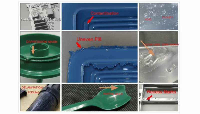
Jakie pytania dotyczące wad formowania wtryskowego PC pojawiają się najczęściej?
Często zadawane pytania
Jaka jest idealna temperatura suszenia poliwęglanu przed wtryskiem?
Poliwęglan powinien być suszony w temperaturze 120°C przy użyciu suszarki odwilżającej przez 3 do 4 godzin, aby osiągnąć zawartość wilgoci poniżej 0,02% przed wtryskowym formowaniem. Jest to bezwzględny wymóg dla skutecznego przetwarzania PC – pominięcie lub skrócenie kroku suszenia jest najczęstszym przyczyną defektów powierzchni. Suszenie ponad 10 godzin grozi degradacją materiału, szczególnie dla gatunków ognioodpornych, które są bardziej wrażliwe termicznie. Zawsze sprawdzaj skuteczność testem strzału powietrznego przed rozpoczęciem produkcji – wydobyta masa powinna być ciągła, gładka i wolna od białej parzy. Użycie standardowej suszarki zasobnikowej bez odwilżania jest niewystarczające dla PC.
Co powoduje czarne plamy w części wtryskowo formowanych z poliwęglanu?
Czarne plamy w części wtryskowo formowanych PC są typowo powodowane przez zwęgielony materiał zatrzymany w martwych strefach systemu plastifikacji – takich jak szczeliny pierścienia kontrolnego ślimaka, interfejsy końcówki dyszy lub zadrapania ścianki cylindra. Zatrzymany materiał degraduje z czasem i okresowo uwalnia się do strumienia masy, produkując ciemne plamy pojawiające się losowo przez kilka strzałów, a następnie znikające. Regularne rozbieranie i czyszczenie systemu plastifikacji, połączone z właściwymi procedurami oczyszczania cylindra przy użyciu PS lub PE przed i po każdej serii produkcyjnej, skutecznie zapobiega temu problemowi. Nigdy nie pozostawiaj materiału PC siedzącego w temperaturze przetwarzania podczas długotrwałych zatrzymań maszyny.
Jaka jest zalecana temperatura wtrysku dla poliwęglanu?
Dla czystego poliwęglanu zalecany profil temperatury cylindra to 250 °C (strefa zasilania) do 285-295 °C (dysza), z temperaturą formy 80-120 °C. Kluczowe jest użycie gradientu temperatury w strefach zamiast pojedynczej wartości zadanej, zapewniając stopniową plastyfikację bez przedwczesnego topienia w strefie zasilania. Modyfikowane gatunki mają różne zakresy: mieszanki PC/ABS pracują około 20 °C niżej, podczas gdy mieszanki PC/PBT mogą wymagać podobnych lub nieco wyższych temperatur. Zawsze zaczynaj od dolnego końca zalecanego zakresu i zwiększaj tylko w przypadku pojawienia się wad przepływu.
Jak zapobiegać naprężeniom wewnętrznym w przezroczystych produktach z PC?
Zapobieganie naprężeniom wewnętrznym w przezroczystych częściach z PC wymaga wielokierunkowego podejścia. Użyj wyższej temperatury stopu, aby zmniejszyć lepkość i orientację molekularną podczas przepływu. Zwiększ temperaturę formy do 100-120 °C dla wolniejszego i bardziej równomiernego chłodzenia, które daje zorientowanym cząsteczkom czas na relaksację. Zminimalizuj ciśnienie wtrysku i docisku do minimum potrzebnego do pełnego napełnienia. Użyj wtrysku ze zmienną prędkością z szybkim napełnianiem, a następnie powolnym dociskiem. Obróbka cieplna po formowaniu w 120 °C przez około 2 godziny jest standardową praktyką dla komponentów klasy optycznej, aby zrelaksować zamrożoną orientację molekularną.
Dlaczego pojawiają się srebrne smugi na części wtryskowo formowanych PC?
Srebrzyste smugi na częściach z PC są spowodowane ucieczką gazu na powierzchnię produktu podczas lub po napełnieniu gniazda, pozostawiając drobne, wydłużone pęcherzyki, które błyszczą w świetle. Najczęstszym źródłem gazu jest para wodna z niedostatecznie wysuszonego materiału – to odpowiada za większość przypadków. Gaz z rozkładu termicznego z powodu nadmiernej temperatury cylindra jest drugą najczęstszą przyczyną. Drobne, gęste srebrzyste smugi skupione w pobliżu bramki w układzie promienistym wskazują na powietrze wtłoczone z powodu nadmiernej prędkości ślimaka lub niewystarczającego ciśnienia wstecznego. Właściwe suszenie w 120 °C przez 3-4 godziny eliminuje większość przypadków spowodowanych wilgocią.
Czy wady wtrysku poliwęglanu można naprawić, dostosowując tylko parametry maszyny?
Wiele defektów PC – szczególnie srebrne smugi, przebarwienia i ślady przepływu – można rozwiązać tylko poprzez regulację parametrów maszyny, głównie warunków suszenia, profilowania temperatury cylindra i optymalizacji szybkości wtrysku. Jednak powtarzające się defekty, takie jak utrzymujące się plamy zimnego materiału lub ślady turbulencji, często wymagają modyfikacji formy, takich jak powiększone otwory wlewowe, dodatkowe kanaliki odpowietrzające lub studzienki na zimne ślizgi. Redukcja naprężeń wewnętrznych może również wymagać zmian w projektowaniu jednolitości grubości ścianki i podgrzewania wkładów. Najskuteczniejsze podejście łączy optymalizację parametrów z właściwym projektem formy od początku.
Jaka jest różnica między pęcherzykami i pęcherzykami próżni w części PC?
Pęcherze w częściach z PC to wypełnione gazem pustki spowodowane parą wodną, wtłoczonym powietrzem lub gazem z rozkładu termicznego uwięzionym podczas napełniania gniazda. Są obecne natychmiast po otwarciu formy i nie rosną z czasem. Pęcherze próżniowe są zasadniczo różne – to pustki indukowane skurczem, które tworzą się podczas chłodzenia, gdy ciśnienie docisku jest niewystarczające, aby skompensować skurcz objętościowy w grubych przekrojach. Pęcherze próżniowe mogą pojawić się lub powiększyć po wyformowaniu, gdy wnętrze nadal się ochładza i kurczy. Różnica diagnostyczna decyduje, czy zajmiesz się zawartością gazu poprzez suszenie i temperaturę, czy dociskiem poprzez ciśnienie docisku.
Jak uzyskać specjalistyczne wsparcie dla projektu formowania wtryskowego PC?
ZetarMold jest partnerem produkcyjnym dla projektów wtrysku poliwęglanu, które wymagają zerowej liczby wad. Nasz zespół inżynierów wnosi do każdego projektu ponad 20-letnie doświadczenie w przetwarzaniu PC i ponad 400 materiałów, od suszenia materiału i profilowania temperatury po projektowanie bramek i odprężanie naprężeń. Nasze wewnętrzne zaplecze narzędziowe, możliwości symulacji MOLDFLOW oraz certyfikowane systemy jakości ISO oznaczają, że Twoje części z PC są zaprojektowane pod kątem jakości już od etapu DFM.
Potrzebujesz wyceny projektu formowania wtryskowego poliwęglanu? Nasz zespół inżynierów przedstawi konkurencyjną cenę, uwagi DFM i harmonogram produkcji. Poproś dziś o bezpłatną wycenę lub zapoznaj się z naszym Kompletnym przewodnikiem po formowaniu wtryskowym, aby uzyskać pełny przegląd procesu.
lepkość stopu pozostaje wysoka: lepkość stopionego PC jest bardziej wrażliwa na zmianę temperatury niż szybkość ścinania, przez co podczas przetwarzania zachowuje się on podobnie do cieczy newtonowskiej. ↩
temperatura zeszklenia PC: poliwęglan ma temperaturę zeszklenia (Tg) około 147-150 C, która określa minimalną temperaturę podtrzymania cieplnego. ↩
zawartość wilgoci poniżej 0.02%: przed przetwarzaniem PC musi mieć zawartość wilgoci poniżej 0.02% (200 ppm), aby zapobiec degradacji hydrolitycznej w temperaturze formowania. ↩