 Zum Inhalt springen

Polycarbonat (PC) ist eines der vielseitigsten technischen Thermoplasten in Spritzgießen—transparent, schlagfest und thermisch stabil. Aber jeder, der PC wirklich auf einer Produktionslinie geführt hat, weiß, dass es auch eines der launischsten Materialien in der Verarbeitung ist. Seine hohe Schmelzviskosität, extreme Feuchtigkeitssensibilität und Tendenz, innere Spannung einzufangen, bedeuten, dass sogar kleine Prozessabweichungen sichtbare Fehler produzieren können: Verfärbung, Silberstreifen, Blasen, Fließmarken und Spannungsbruch.
In diesem Artikel gehen wir die sechs häufigsten PC-Formungsfehler durch, die wir in der Produktion erleben – Verfärbung und schwarze Flecken, Silberstreifen und Blasen, Fließmarken, Kaltmaterialflecken und innere Spannungsbrüche. Für jeden Fehler erklären wir den physikalischen Mechanismus, wie man ihn aus dem Fehlerbild diagnostiziert und die spezifischen Prozess- und Werkzeuganpassungen, die ihn beheben. Diese Einsichten kommen aus zwei Jahrzehnten praktischer PC-Formungs-Erfahrung in Automobil-, Medizin- und Konsumelektronik-Anwendungen.

- PC moisture sensitivity (requires <0.02% moisture) is the root cause of most surface defects
- Eine höhere Schmelzviskosität als ABS oder PP bedeutet, dass PC eine präzise Temperatur- und Drucksteuerung benötigt
- Innere Spannung in transparenten PC-Teilen kann verzögertes Bruchverhalten Tage nach dem Formen verursachen
- Die meisten Defekte haben gemeinsame Lösungen: richtiges Trocknen, optimierte Zylindertemperatur und ausreichende Formentlüftung
- Fabrikerfahrungen mit über 400 Materialien zeigen, dass allein durch konsequente Trocknung 60% der PC-Fehler beseitigt werden
Was macht das Spritzgießen von Polycarbonat so herausfordernd?
Polycarbonat ist einer der schwierigsten technischen Thermoplaste zum Spritzgießen. Seine einzigartige Molekularstruktur – lineare Ketten mit Benzolringen, Isopropylidengruppen und Carbonatbindungen – schafft drei zentrale Verarbeitungsherausforderungen, die es von einfacheren Materialien wie Polypropylen oder ABS unterscheiden.
If you are comparing vendors or planning procurement, our injection molding supplier sourcing guide covers RFQ prep, qualification, and commercial risk checks.
Zuerst hat PC keinen klaren Schmelzpunkt. Es weichert stattdessen graduell über einen breiten Temperaturbereich (230–320 °C), was bedeutet Schmelzviskosität bleibt hoch1 während der normalen Verarbeitung. Im Gegensatz zu teilkristallinen Polymeren, die deutlich oberhalb ihres Schmelzpunkts dünnflüssiger werden, verhält sich PC eher wie eine Newtonsche Flüssigkeit – seine Viskosität ist empfindlicher gegenüber Temperaturänderungen als gegenüber der Scherrate. Kleine Temperaturabweichungen von nur 10–15 °C können die Schmelze von verarbeitbar zu abgebaut bringen.
Zweitens ist PC extrem feuchtigkeitsempfindlich. Selbst Spuren von Wasser (über 0,02 % nach Gewicht) verursachen bei Verarbeitungstemperaturen hydrolytischen Abbau, der Polymerketten bricht und mechanische Eigenschaften reduziert. Das bedeutet, dass gründliches Vortrocknen bei 120 °C für 3–4 Stunden obligatorisch ist – nicht optional. Nach unserer Erfahrung beim Verarbeiten von über 400 Materialien in der Shanghai-Fabrik machen feuchtigkeitsbedingte Defekte etwa 60 % aller PC-Spritzgießprobleme aus, die wir beheben.
In unserer Fabrik in Shanghai, mit über 20 Jahren Spritzgießerfahrung über 400+ Kunststoffmaterialien hinweg, haben wir jedes vorstellbare PC-Defektmuster gesehen. Feuchtigkeitskontrolle und Disziplin bei der Zylindertemperatur sind die beiden Variablen, die einen reibungslosen PC-Produktionslauf von einem kostspieligen Ausschussereignis trennen.
Drittens bedeutet die hohe Viskosität der PC-Schmelze, dass Spritzgussform Das Design muss höhere Einspritzdrücke, größere Angüsse und Läufe sowie tiefer Entlüftungsnuten ermöglichen, als für Standardkunststoffe benötigt würden. Unterdimensionierte Fließkanäle erzeugen übermäßige Scherhitze, die paradoxerweise thermische Degradation verursacht, auch wenn Zylindertemperaturen korrekt eingestellt sind. Das Verständnis dieser drei Einschränkungen – hohe Viskosität, Feuchtigkeitssensibilität und Schersensibilität – ist die Grundlage für die Vermeidung jedes Fehlers, der in diesem Artikel behandelt wird.

Was verursacht Verfärbung, Vergilbung und schwarze Flecken in PC-Teilen?
Verfärbung ist der häufigste visuelle Defekt beim PC-Spritzgießen, verursacht durch thermischen Abbau der Schmelze. Die Hauptursache ist typischerweise eine übermäßige Zylindertemperatur, eine zu lange Verweilzeit oder Totzonen im Plastifiziersystem, in denen abgebautes Material akkumuliert und intermittierend in den Schmelzstrom freigesetzt wird.
Reines PC-Harz hat eine ausgezeichnete thermische Stabilität und kann Temperaturen von bis zu 300 °C ohne signifikanten Abbau tolerieren. Das Problem entsteht, wenn Verarbeiter modifizierte PC-Blends, recyceltes Material oder PC mit Flammschutzmitteln und Füllstoffen verwenden. Diese Additive verringern das Verarbeitungsfenster erheblich. Zum Beispiel benötigen PC/ABS-Blends typischerweise Zylindertemperaturen um 250 °C, während PC/PBT-Blends für Beleuchtungsprodukte etwa 280 °C benötigen – jede Kombination hat ihre eigene thermische Obergrenze, die, wenn sie überschritten wird, irreversible Vergilbung oder Verkohlung auslöst.
Schwarze Flecken sind eine besonders frustrierende Variante, weil sie intermittierend auftreten können – manchmal zwei oder drei Schüsse in Folge, dann verschwinden sie. Dieses Bild deutet fast immer auf abgestandenes Material hin, das irgendwo im Plastifiziersystem eingeschlossen ist: Spaltungen im Schrauben-Rückschlagventil, Düsenspitzen-Übergänge oder Zylinderwand-Abrieb. Das eingeschlossene Material verkohlt über Zeit und bricht dann in Klumpen los. Wenn PC-Abbauprodukte über einen kritischen Grenzwert akkumulieren, katalysieren sie auch weiteren Abbau, erzeugen einen Kaskaden-Effekt – besonders schwer in flammhemmenden Klassen.
| PC-Materialtyp | Empfohlene Zylindertemperatur | Abbaurisiko oberhalb |
|---|---|---|
| Reines PC (optische Klasse) | 270-300 °C | 320 °C |
| PC/ABS blend | 240-260 °C | 280 °C |
| PC mit Flammschutzmittel | 230-260 °C | 280 °C |
| PC/PBT-Blend (Beleuchtung) | 260-280 °C | 300 °C |
| Recyceltes PC | 240-270 °C | 290 °C (variabel) |
Die Lösungen sind systematisch. Erstens: Überprüfen Sie die Zylindertemperatur-Sollwerte entsprechend des Materialtyps und reduzieren Sie die Temperaturen in der Einzugszone und der Kompressionszone in Schritten von 5–10 °C, bis die Verfärbung aufhört. Zweitens: Stellen Sie gründliches Trocknen sicher: 120 °C für 3–4 Stunden mit einem Entfeuchtertrockner, niemals länger als 10 Stunden, um Materialalterung zu vermeiden. Drittens: Untersuchen Sie das Plastifiziersystem auf Totzonen – entfernen und reinigen Sie die Düse, den Rückschlagring und die Schnecke, wenn die Luftschuss-Schmelze selbst bei korrekten Temperaturen Verfärbung zeigt. Schließlich: Spülen Sie den Zylinder vor und nach jedem Produktionslauf mit einem thermisch stabilen Material (PS oder PE) und lassen Sie PC niemals während längerer Stopps auf Verarbeitungstemperatur stehen; senken Sie den Zylinder auf 160 °C (PC-Glasübergang2) oder darunter für thermische Haltezeiten.
“Lowering barrel temperature is always the first step when PC parts show yellowing.”Wahr
Die Reduzierung der Zylindertemperatur ist die richtige erste Maßnahme, weil übermäßige Hitze die häufigste Ursache für PC-Verfärbung ist. Wenn die Verfärbung jedoch nach einer Reduzierung von 10–15 °C bestehen bleibt, liegt die Ursache wahrscheinlich in abgestandenem Material im Plastifiziersystem oder in verunreinigten Rohmaterialien.
“Using higher back pressure always improves PC melt quality.”Falsch
Übermäßiger Gegendruck erzeugt zusätzliche Scherwärme im Zylinder, was den thermischen Abbau von PC beschleunigen kann. Der richtige Ansatz ist mäßiger Gegendruck (0,5-1,5 MPa) kombiniert mit ausreichender Trocknung und geeigneter Zylindertemperaturprofilierung.
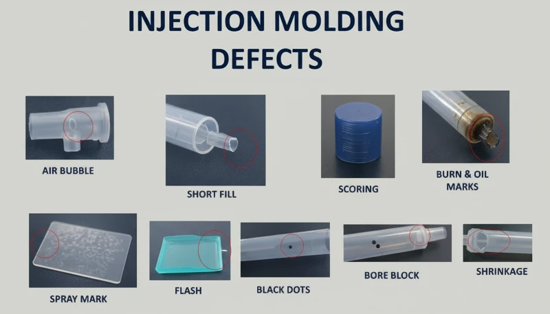
Warum treten Silberstreifen und Blasen auf PC-Produkten auf?
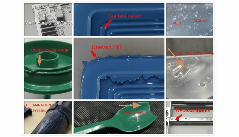
Silberstreifen (auch Gasstreifen genannt) und Blasen sind Oberflächen- und innere Defekte, die durch im Schmelzfluss eingeschlossene Gase während der Kavitätsfüllung verursacht werden. Beim PC-Spritzgießen sind die vier Gasquellen Wasserdampf, eingeschlossene Luft, thermische Zersetzungsgase und Lösungsmittelgase – Wasserdampf und Zersetzungsgase machen den Großteil der Fälle aus.
Silver streaks form when gas dissolved in the pressurized melt escapes to the product surface as cavity pressure drops after filling. The escaping gas leaves tiny elongated bubbles that sparkle under light, always aligned with material flow direction. Bubbles, on the other hand, are gas pockets trapped in the wall thickness—particularly visible in transparent PC parts. Vacuum bubbles are different: they form not from gas but from volumetric shrinkage when insufficient holding pressure leaves a void in thick sections.
How to Diagnose the Gas Source Behind Silver Streaks
Diagnosing which gas is responsible requires reading the defect pattern. Randomly scattered surface bubbles point to water vapor—the most common culprit in PC because the material is so hygroscopic. Fine, dense bubble clusters concentrated near the gate in a radial or fan-shaped pattern indicate entrained air, typically from excessive screw retraction speed or insufficient back pressure. Discoloration accompanying the silver streaks points to decomposition gas from overheated melt. The diagnostic process matters because each gas source requires a different fix.
For moisture-driven silver streaks, the solution is straightforward: ensure drying at 120 °C for 3–4 hours with a dehumidifying dryer. Verify effectiveness by air-shooting—the extruded melt should be continuous, smooth, and free of white vapor. For air entrainment, reduce screw speed, increase back pressure, and extend melt time during the cooling phase. For decomposition gas, lower barrel temperature section by section starting from the nozzle, and check for excessively long residence times (using oversized equipment for small parts is a common culprit).
Vacuum bubbles require a different approach because they are a shrinkage phenomenon, not a gas issue. Increase holding pressure and extend holding time to pack more material into the thick section. Position the gate at the thickest wall to ensure pressure transmission. Increase mold temperature locally at the void location to slow solidification and allow shrinkage compensation. For transparent products, post-mold slow cooling in hot water can also reduce vacuum bubble formation.
“Post-molding heat treatment at 120 C for 2 hours can significantly reduce internal stress in PC parts.”Wahr
Heat treatment at approximately 120 C allows PC molecular chain segments to regain mobility and relax frozen elastic deformation. Oriented molecules return toward a random state, reducing both orientation and temperature stress. This is standard practice for optical and stress-critical PC applications.
“Vacuum bubbles in PC parts are caused by trapped air.”Falsch
Vacuum bubbles are actually caused by volumetric shrinkage during cooling, not trapped air. When holding pressure is insufficient or the gate freezes too early, the still-molten core shrinks away from the already-solidified skin, creating a void. The fix is increased holding pressure and time, not venting.
What Are Fingerprint Marks and Turbulence Lines—and How Do You Fix Them?
Fingerprint marks and turbulence lines are flow defects caused by PC melt viscosity being too high relative to injection speed and mold temperature. The melt fills the cavity in a stick-slip pattern, leaving wavy lines perpendicular to flow direction (fingerprints) or radial streaks near the gate (turbulence).
Fingerprint marks develop when injection speed and pressure are too low for the melt viscosity. The front of the melt stream contacts the cold mold wall, solidifies, and shrinks. The hot melt behind it pushes the shrunken skin forward, then that layer also cools and shrinks. This alternating advance-freeze cycle creates the characteristic wavy pattern that looks like a human fingerprint. The effect is most visible on large, flat PC surfaces—think display covers or control panels.
Turbulence marks are related but distinct. They appear as irregular flow lines radiating from the gate, caused by the melt hitting the cavity wall at high velocity and skidding across the cold surface before stabilizing into laminar flow. This defect is particularly common when gate design creates a sharp velocity transition—such as a small gate feeding into a large, thick cavity. The key distinction: fingerprints run perpendicular to flow, while turbulence lines run parallel.
Both defects share the same solution set. Increase the nozzle and front barrel temperatures to reduce melt viscosity—this is the single most effective adjustment. Raise mold temperature, especially at the location where marks appear; for appearance-critical PC parts, a mold temperature controller set to 100–120 °C is standard practice. Increase injection speed to shift the filling pattern from stick-slip to continuous flow; multi-stage injection allows you to adjust speed section by section, targeting the problem area without causing flash elsewhere. On the mold side, enlarge gates and runners to reduce flow resistance, and ensure adequate venting and cold-slug wells.
With 47 injection machines ranging from 90T to 1850T, and MOLDFLOW simulation for gate and runner optimization, we typically resolve flow mark issues during the DFM stage—before steel is ever cut. Simulation catches the velocity transitions that cause turbulence marks, allowing gate redesign before tooling.
How Do Cold Material Spots Form and How Can You Prevent Them?
Cold material spots are foggy, bright, or worm-shaped marks near the gate caused by partially solidified melt entering the cavity. They form when the melt front loses too much heat at the nozzle tip, runner, or gate before cavity filling begins—or when excessive holding pressure forces already-cooled runner material into the part.
There are two distinct mechanisms. The first is forward cold material: the melt at the nozzle tip and runner entrance cools between shots because the nozzle contacts the cold mold plate. When injection begins, this chilled material enters the cavity first. On thin-walled parts, it spreads into smoky or paste-like cloudy patches. On thick-walled parts, it forms a curved scar resembling an earthworm. The second mechanism is back-pressure cold material: excessive holding time and pressure squeeze already-cooled material from the runner and gate into the part, creating a small circular bright spot near the gate.
Prevention is straightforward but requires attention to detail. Install a cold-slug well at the end of each runner—this traps the forward cold material before it enters the cavity. Increase nozzle temperature to reduce heat loss at the tip. Increase mold temperature to narrow the gap between melt and mold surface temperatures. Reduce injection speed at the start of filling to avoid melt fracture at the gate, then increase speed for the main fill. Optimize gate position, size, and shape to avoid sharp velocity transitions. For holding-pressure cold spots, shorten holding time and reduce holding pressure to the minimum needed for dimensional stability. Also ensure thorough material drying—residual moisture in the cold-slug can worsen the visual defect.
Why Does Internal Stress Crack Transparent PC Products?
Internal stress in PC products is frozen-in molecular orientation and uneven cooling stress. It can cause warpage, reduced optical clarity, and delayed stress cracking days or weeks after molding—transparent PC parts are the canary in the coal mine.
Two primary mechanisms create internal stress. Orientation stress comes from polymer chains being stretched during flow and then frozen in place before they can relax back to a random coil configuration. Higher injection pressure, faster injection speed, and longer holding time all increase orientation by applying more shear to the melt. Temperature stress comes from the large temperature differential between the hot melt core and the cold mold wall. Because PC has high specific heat capacity and low thermal conductivity, the surface solidifies long before the interior—creating compressive stress on the outside and tensile stress on the inside.
The practical consequence is that a PC part may look perfect immediately after molding but develop micro-cracks within days, especially when exposed to organic solvents (cleaning agents, adhesives) or elevated temperatures. In our production environment, we have seen transparent PC lenses crack during assembly simply because the operator used an alcohol-based cleaning wipe—the internal stress was already at the failure threshold, and the solvent lowered it just enough to initiate cracking.
Our in-house mold manufacturing facility (100+ mold sets per month) allows us to optimize gate placement, runner geometry, and cooling channel layout specifically for stress-sensitive PC parts. Combined with ISO 9001 and ISO 13485 quality systems, we catch internal stress issues during first-article inspection using polarized light analysis.
“Polarized light analysis can detect internal stress in transparent PC parts before they crack.”Wahr
Under polarized light, stressed PC exhibits birefringence patterns that reveal frozen molecular orientation and uneven cooling stress. This non-destructive inspection method allows factories to catch stress issues during first-article inspection, long before parts fail in service.
“Post-mold annealing at 120 C reduces internal stress in transparent PC parts.”Falsch
Annealing at 120 C does indeed reduce internal stress by allowing molecular chains to relax. However, it is not a substitute for proper molding parameters—it can only reduce stress that was created, not eliminate it entirely. The most effective approach is to minimize stress during molding through correct temperature and pressure settings, then use annealing as a final quality assurance step for critical components.
Reducing internal stress requires a holistic approach. Increase melt temperature to reduce viscosity and orientation during flow. Increase mold temperature to allow slower, more uniform cooling and give oriented molecules time to relax. Reduce injection pressure to the minimum needed for complete filling. Minimize holding time—over-packing is a major contributor to orientation stress. Use variable-speed injection: fast fill to avoid flow defects, then slow speed for holding to reduce molecular alignment. For parts with metal inserts, preheat inserts to approximately 200 °C to reduce the thermal mismatch. Finally, post-mold heat treatment at 120 °C for approximately 2 hours allows chain segments to regain mobility and relax frozen deformation—this is standard practice for optical-grade PC components.
“Reducing injection pressure to the minimum needed for cavity filling helps prevent internal stress in PC parts.”Wahr
Excessive injection pressure increases molecular orientation and shear stress, which increases internal stress and the risk of warpage and stress cracking. The minimum pressure that achieves complete filling, combined with adequate melt temperature, produces the lowest-stress PC parts.
“Increasing mold temperature above 100 °C always improves the surface finish of PC parts.”Falsch
While higher mold temperature can reduce flow marks and improve surface gloss, exceeding 100 °C for extended cycles can cause excessively long cooling times and lead to thermal degradation of the PC resin near the gate. The optimal mold temperature range for PC is typically 80–100 °C, balancing finish quality with cycle efficiency and part stability.
What Processing Parameters Should You Monitor to Minimize PC Defects?
There are six parameters that matter most for PC defect prevention: drying, barrel temperature, injection speed, hold pressure, and mold temperature. Getting these right eliminates the vast majority of discoloration, silver streaks, bubbles, flow marks, and internal stress issues.
Drying is non-negotiable. PC requires moisture content below 0.02%3—achieved by dehumidifying dryer at 120 °C for 3–4 hours. Drying beyond 10 hours risks material degradation, especially for flame-retardant grades. Verify drying effectiveness by air-shot inspection before starting production. This single step prevents most silver streaks and surface bubbles.
Barrel temperature must be set as a profile, not a single number. For pure PC, a typical profile runs 250 °C (feed) → 270 °C (compression) → 285 °C (metering) → 290 °C (nozzle). Each modified grade has its own window—PC/ABS at roughly 20 °C lower, PC/PBT at similar or slightly higher temperatures. The key is to start at the lower end of the recommended range and increase only if flow marks or short shots appear. Never set all zones to the same temperature; a proper gradient ensures gradual plasticization without premature melting in the feed zone (which blocks air escape) or under-preheating (which traps air in the melt).
| Parameter | Recommended Range (Pure PC) | Defects Prevented |
|---|---|---|
| Drying temperature | 120 C, 3-4 h, dehumidified | Silver streaks, surface bubbles |
| Barrel temperature (nozzle) | 280-295 C | Short shots, flow marks |
| Temperatur der Form | 80-120 C | Fingerprint marks, internal stress |
| Einspritzgeschwindigkeit | Multi-stage: fast fill, slow pack | Turbulence marks, over-packing |
| Nachdruck | 60-80% of injection pressure | Vacuum bubbles, sink marks |
| Holding time | Until gate freeze (3-8 s) | Shrinkage voids, dimensional drift |
Melt residence time deserves special attention. Using oversized equipment for small PC parts is a common mistake—the large shot-to-barrel-capacity ratio means material sits at processing temperature far too long, accumulating thermal damage. As a rule of thumb, the shot weight should be at least 30–40% of the barrel capacity. If you must run small parts on large machines, use a smaller-diameter screw or accept that frequent purging and color changes are unavoidable. Finally, mold temperature matters more for PC than for most plastics. Running cold molds (below 80 °C) accelerates skin solidification, increases internal stress, and amplifies flow marks. For transparent or appearance-critical parts, 100–120 °C mold temperature with a temperature controller is the industry standard.
What Are the Most Common Questions About PC Injection Molding Defects?
Häufig gestellte Fragen
What is the ideal drying temperature for polycarbonate before injection molding?
Polycarbonate should be dried at 120 C using a dehumidifying dryer for 3 to 4 hours to achieve moisture content below 0.02% before injection molding. This is a non-negotiable requirement for successful PC processing—skipping or short-cutting the drying step is the single most common cause of surface defects. Drying beyond 10 hours risks material degradation, especially for flame-retardant grades which are more thermally sensitive. Always verify effectiveness with an air-shot test before production begins—the extruded melt should be continuous, smooth, and free of white vapor. Using a standard hopper dryer without dehumidification is insufficient for PC.
What causes black spots in polycarbonate injection molded parts?
Black spots in PC injection molded parts are typically caused by carbonized material trapped in dead zones of the plasticizing system—such as screw check ring gaps, nozzle tip interfaces, or barrel wall scoring. The trapped material degrades over time and intermittently breaks loose into the melt stream, producing dark spots that appear randomly across several shots then disappear. Regular disassembly and cleaning of the plasticizing system, combined with proper barrel purging procedures using PS or PE before and after each production run, prevents this issue effectively. Never leave PC material sitting at processing temperature during extended machine stops.
What is the recommended injection molding temperature for polycarbonate?
For pure polycarbonate, the recommended barrel temperature profile is 250 C (feed zone) to 285-295 C (nozzle), with mold temperature at 80-120 C. The key is to use a temperature gradient across zones rather than a single setpoint, ensuring gradual plasticization without premature melting in the feed zone. Modified grades have different windows: PC/ABS blends run approximately 20 C lower, while PC/PBT blends may require similar or slightly higher temperatures. Always start at the lower end of the recommended range and increase only if flow defects appear.
How do you prevent internal stress in transparent PC products?
Preventing internal stress in transparent PC parts requires a multi-pronged approach. Use higher melt temperature to reduce viscosity and molecular orientation during flow. Increase mold temperature to 100-120 C for slower and more uniform cooling that gives oriented molecules time to relax. Minimize injection and holding pressure to the minimum needed for complete filling. Use variable-speed injection with fast fill followed by slow pack. Post-mold heat treatment at 120 C for approximately 2 hours is standard practice for optical-grade components to relax frozen molecular orientation.
Why do silver streaks appear on PC injection molded parts?
Silver streaks on PC parts are caused by gas escaping to the product surface during or after cavity filling, leaving tiny elongated bubbles that sparkle under light. The most common gas source is water vapor from inadequately dried material—this accounts for the majority of cases. Thermal decomposition gas from excessive barrel temperature is the second most common cause. Fine dense silver streaks concentrated near the gate in a radial pattern indicate entrained air from excessive screw speed or insufficient back pressure. Proper drying at 120 C for 3-4 hours eliminates most moisture-driven cases.
Can polycarbonate injection molding defects be fixed by adjusting only the machine parameters?
Many PC defects—particularly silver streaks, discoloration, and flow marks—can be resolved through machine parameter adjustments alone, primarily drying conditions, barrel temperature profiling, and injection speed optimization. However, recurring defects like persistent cold material spots or turbulence marks often require mold modifications such as enlarged gates, additional venting channels, or cold-slug wells. Internal stress reduction may also require design changes to wall thickness uniformity and insert preheating. The most effective approach combines parameter optimization with proper mold design from the start.
What is the difference between bubbles and vacuum bubbles in PC parts?
Bubbles in PC parts are gas-filled voids caused by water vapor, entrained air, or thermal decomposition gas trapped during cavity filling. They are present immediately upon mold opening and do not grow over time. Vacuum bubbles are fundamentally different—they are shrinkage-induced voids that form during cooling when holding pressure is insufficient to compensate for volumetric shrinkage in thick sections. Vacuum bubbles may appear or enlarge after demolding as the interior continues to cool and contract. The diagnostic difference determines whether you address gas content through drying and temperature, or packing through holding pressure.
How Can You Get Expert Support for Your PC Injection Molding Project?
ZetarMold is the manufacturing partner for polycarbonate injection molding projects that demand zero defects. Our engineering team brings 20+ years of experience processing PC and 400+ materials to every project, from material drying and temperature profiling to gate design and stress relief. Our in-house tooling facility, MOLDFLOW simulation capability, and ISO-certified quality systems mean your PC parts are engineered for quality from the DFM stage onward.
Need a quote for your polycarbonate injection molding project? Get competitive pricing, DFM feedback, and production timeline from our engineering team. Request a Free Quote today, or explore our Injection Molding Complete Guide for a comprehensive overview of the process.
-
Schmelzviskosität bleibt hoch: melt viscosity remains high refers to pC melt viscosity is more sensitive to temperature changes than to shear rate, behaving similarly to a Newtonian fluid during processing. ↩
-
PC-Glasübergang: PC glass transition refers to polycarbonate has a glass transition temperature (Tg) of approximately 147-150 C, which determines minimum thermal hold temperature. ↩
-
moisture content below 0.02%: moisture content below 0.02% refers to pC requires moisture content below 0.02% (200 ppm) before processing to prevent hydrolytic degradation at molding temperatures. ↩


