 Overslaan naar inhoud

Polycarbonaat (PC) is een van de meest veelzijdige technische thermoplasten in spuitgieten—transparant, slagvast en thermisch stabiel. Maar iedereen die PC op een productielijn heeft gebruikt, weet dat het ook een van de lastigste materialen is om te verwerken. De hoog smeltviscositeit, extreme gevoeligheid voor vocht en de tendens om interne spanning te vasthouden betekenen dat zelfs kleine procesafwijkingen zichtbare defecten kunnen veroorzaken: verkleuring, zilverstrepen, bubbels, stromingsmarkeringen en spanningbreuk.
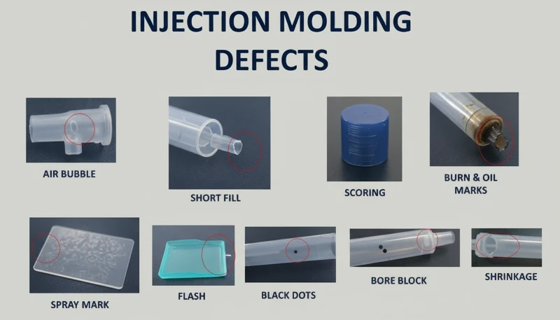
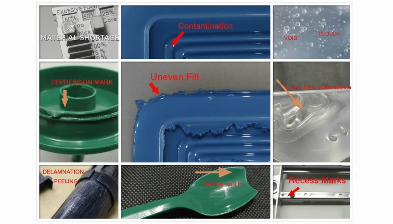
In dit artikel bespreken we de zes meest voorkomende PC-gietdefecten die we in de productie tegenkomen—verkleuring en zwarte vlekken, zilverstrepen en bubbels, stroomsporen, koude materiaalvlekken en inwendige spanningsscheuren. Voor elk defect leggen we het fysieke mechanisme uit, hoe het te diagnosticeren aan de hand van het defectpatroon, en de specifieke proces- en gereedschapsaanpassingen die het oplossen. Deze inzichten komen uit twee decennia praktijkervaring met PC-spuitgieten in de auto-, medische- en consumentenelektronica-industrie.

- PC vochtgevoeligheid (vereist <0.02% vocht) is de oorzaak van meeste oppervlakdefecten
- Een hogere smeltviscositeit dan ABS of PP betekent dat PC nauwkeurige temperatuur- en drukregeling nodig heeft
- Inwendige spanning in transparante PC-onderdelen kan vertraagde scheuren veroorzaken, dagen na het gieten
- De meeste defecten hebben gemeenschappelijke oplossingen: goed drogen, geoptimaliseerde cilindertemperatuur en voldoende ontluchting van het matrijs
- Fabriekservaring met 400+ materialen toont dat droogdiscipline alleen 60% van PC-defecten elimineert
Waarom is Spuitgieten van Polycarbonaat Zo Uitdagend?
Polycarbonaat is een van de moeilijkste technische thermoplasten om te spuitgieten. De unieke moleculaire structuur—lineaire ketens met benzenringen, isopropyliden-groepen en carbonaatverbindingen—creëert drie kernverwerkingsproblemen die het anders maken dan gemakkelijke materialen zoals polypropyleen of ABS.
If you are comparing vendors or planning procurement, our injection molding supplier sourcing guide covers RFQ prep, qualification, and commercial risk checks.
Ten eerste heeft PC geen scherp smeltpunt. In plaats daarvan wordt het geleidelijk zachter over een breed temperatuurbereik (230–320 °C), wat betekent smeltviscositeit blijft hoog1 door normale verwerking. In tegenstelling tot semi-crystalline polymeren die dramatisch dunner worden boven hun smeltpunt, gedraagt PC zich meer als een Newtoniaanse vloeistof—de viscositeit is meer gevoelig voor temperatuurveranderingen dan voor schuifsnelheid. Kleine temperatuurdeviaties van slechts 10–15 °C kunnen de smelt van procesbaar naar gedegradeerd brengen.
Ten tweede, PC is extreem gevoelig voor vocht. Zelfs kleine hoeveelheden water (boven 0.02% op gewicht) veroorzaken hydrolytische degradatie bij verwerkingstemperaturen, waardoor polymerketens breken en mechanische eigenschappen verminderen. Dit betekent dat grondige voorafdroging bij 120 °C voor 3–4 uur noodzakelijk is—niet optioneel. In onze ervaring met het verwerken van meer dan 400 materialen in de Shanghai fabriek, vochtgerelateerde defecten vormen ongeveer 60% van alle PC-gietproblemen die we oplossen.
In onze fabriek in Shanghai, met 20+ jaar spuitgietervaring met 400+ plasticmaterialen, hebben we elk PC-defectpatroon gezien. Vochtcontrole en cilindertemperatuurdiscipline zijn de twee variabelen die een soepele PC-productie scheiden van een kostbare afvalgebeurtenis.
Ten derde, de hoog viscositeit van PC-smelt betekent dat spuitgietvorm Het ontwerp moet hogere injectiedrukken, grotere openingen en runners en diepere uitlaatgroeven accommoderen dan wat nodig is voor commodity plastics. Ondergeproportioneerde stromingskanalen creëren excessieve schuifwarmte, wat paradoxaal thermische degradatie veroorzaakt zelfs wanneer de cilindertemperaturen correct zijn ingesteld. Begrip van deze drie beperkingen—hoge viscositeit, vochtgevoeligheid en schuifgevoeligheid—is de basis voor het voorkomen van elke defect die in dit artikel wordt behandeld.

Wat Veroorzaakt Verkleuring, Vergeling en Zwarte Vlekken in PC-onderdelen?
Verkleuring is het meest voorkomende visuele defect bij het spuitgieten van PC, veroorzaakt door thermische degradatie van de smelt. De hoofdoorzaak is meestal een te hoge cilindertemperatuur, een te lange verblijftijd, of dode zones in het plastificeersysteem waar gedegradeerd materiaal zich ophoopt en af en toe in de smeltstroom terechtkomt.
Pure PC-hars heeft excellent thermische stabiliteit en kan temperaturen tot 300 °C verdragen zonder significante decompositie. Het probleem ontstaat wanneer verwerkers gemodificeerde PC-mengsels, gerecycled materiaal, of PC gecomposteerd met brandvertragers en vulstoffen gebruiken. Deze additieven verkleinen het verwerkingswindow sterk. Bijvoorbeeld, PC/ABS-mengsels vereisen cilindertemperaturen rond 250 °C, terwijl PC/PBT-mengsels voor lichtproducten ongeveer 280 °C nodig hebben—elk combinatie heeft zijn eigen thermische limiet die, wanneer overschreden, onomkeerbare vergeling of carbonisatie triggert.
Zwarte vlekken zijn een bijzonder frustrerende variant omdat ze intermitterend kunnen optreden—soms twee of drie schoten achter elkaar, dan weer verdwijnend. Dit patroon wijst bijna altijd op dood materiaal dat ergens in het plastificeersysteem vastzit: openingen in de terugslagring van de schroef, raakvlakken van de spuitkop, of krassen op de cilinderwand. Het vastzittende materiaal verkoolt na verloop van tijd en breekt dan in brokken los. Wanneer PC-afbraakproducten zich ophopen boven een kritieke drempel, katalyseren ze ook verdere afbraak, wat een cascade-effect creëert—vooral ernstig bij vlamvertragende kwaliteiten.
| PC Materiaaltype | Aanbevolen Cilindertemperatuur | Degradatierisico Boven |
|---|---|---|
| Pure PC (optische kwaliteit) | 270-300 °C | 320 °C |
| ISO 10993: | 240-260 C | 280 °C |
| PC met vlamvertrager | 230-260 °C | 280 °C |
| PC/PBT-mengsel (verlichting) | 260-280 °C | 300 °C |
| Gerecycled PC | 240-270 °C | 290 °C (variabel) |
De oplossingen zijn systematisch. Ten eerste: controleer de temperatuurinstellingen van de cilinder op basis van het materiaaltype en verlaag de temperatuur in de invoer- en compressiezones in stappen van 5–10 °C tot de verkleuring stopt. Ten tweede: zorg voor grondig drogen: 120 °C gedurende 3–4 uur met een ontvochtigingsdroger, nooit langer dan 10 uur om veroudering van het materiaal te voorkomen. Ten derde: inspecteer het plastificeersysteem op dode zones—verwijder en reinig de spuitkop, controleer de terugslagring en de schroef als de gesmolten luchtstoot verkleuring vertoont, zelfs bij de juiste temperaturen. Tot slot: spoel de cilinder voor en na elke productierun door met een thermisch stabiel materiaal (PS of PE), en laat PC nooit langdurig op verwerkingstemperatuur staan tijdens onderbrekingen; verlaag de cilindertemperatuur tot 160 °C (PC glasovergang2) of lager voor thermische houds.
“Lowering barrel temperature is always the first step when PC parts show yellowing.”Echt
Lowering barrel temperature is the correct first response because excessive heat is the most common cause of PC yellowing. However, if discoloration persists after a 10-15 C reduction, the root cause likely shifts to dead material in the plasticizing system or contaminated raw material.
“Using higher back pressure always improves PC melt quality.”Vals
Excessive back pressure generates additional shear heat in the barrel, which can accelerate thermal degradation of PC. The correct approach is moderate back pressure (0.5-1.5 MPa) combined with adequate drying and proper barrel temperature profiling.
Waarom ontstaan zilverstrepen en bubbels op PC-producten?
Silver streaks (also called gas streaks) and bubbles are surface and internal defects caused by gas trapped in the melt during cavity filling. In PC injection molding, the four gas sources are water vapor, entrained air, thermal decomposition gas, and solvent gas—water vapor and decomposition gas account for the vast majority of cases.
Silver streaks form when gas dissolved in the pressurized melt escapes to the product surface as cavity pressure drops after filling. The escaping gas leaves tiny elongated bubbles that sparkle under light, always aligned with material flow direction. Bubbles, on the other hand, are gas pockets trapped in the wall thickness—particularly visible in transparent PC parts. Vacuum bubbles are different: they form not from gas but from volumetric shrinkage when insufficient holding pressure leaves a void in thick sections.
How to Diagnose the Gas Source Behind Silver Streaks
Diagnosing which gas is responsible requires reading the defect pattern. Randomly scattered surface bubbles point to water vapor—the most common culprit in PC because the material is so hygroscopic. Fine, dense bubble clusters concentrated near the gate in a radial or fan-shaped pattern indicate entrained air, typically from excessive screw retraction speed or insufficient back pressure. Discoloration accompanying the silver streaks points to decomposition gas from overheated melt. The diagnostic process matters because each gas source requires a different fix.
For moisture-driven silver streaks, the solution is straightforward: ensure drying at 120 °C for 3–4 hours with a dehumidifying dryer. Verify effectiveness by air-shooting—the extruded melt should be continuous, smooth, and free of white vapor. For air entrainment, reduce screw speed, increase back pressure, and extend melt time during the cooling phase. For decomposition gas, lower barrel temperature section by section starting from the nozzle, and check for excessively long residence times (using oversized equipment for small parts is a common culprit).
Vacuum bubbles require a different approach because they are a shrinkage phenomenon, not a gas issue. Increase holding pressure and extend holding time to pack more material into the thick section. Position the gate at the thickest wall to ensure pressure transmission. Increase mold temperature locally at the void location to slow solidification and allow shrinkage compensation. For transparent products, post-mold slow cooling in hot water can also reduce vacuum bubble formation.
“Post-molding heat treatment at 120 C for 2 hours can significantly reduce internal stress in PC parts.”Echt
Heat treatment at approximately 120 C allows PC molecular chain segments to regain mobility and relax frozen elastic deformation. Oriented molecules return toward a random state, reducing both orientation and temperature stress. This is standard practice for optical and stress-critical PC applications.
“Vacuum bubbles in PC parts are caused by trapped air.”Vals
Vacuum bubbles are actually caused by volumetric shrinkage during cooling, not trapped air. When holding pressure is insufficient or the gate freezes too early, the still-molten core shrinks away from the already-solidified skin, creating a void. The fix is increased holding pressure and time, not venting.
Wat zijn vingerafdrukken en turbulentielijnen—en hoe kun je ze oplossen?
Fingerprint marks and turbulence lines are flow defects caused by PC melt viscosity being too high relative to injection speed and mold temperature. The melt fills the cavity in a stick-slip pattern, leaving wavy lines perpendicular to flow direction (fingerprints) or radial streaks near the gate (turbulence).
Fingerprint marks develop when injection speed and pressure are too low for the melt viscosity. The front of the melt stream contacts the cold mold wall, solidifies, and shrinks. The hot melt behind it pushes the shrunken skin forward, then that layer also cools and shrinks. This alternating advance-freeze cycle creates the characteristic wavy pattern that looks like a human fingerprint. The effect is most visible on large, flat PC surfaces—think display covers or control panels.
Turbulence marks are related but distinct. They appear as irregular flow lines radiating from the gate, caused by the melt hitting the cavity wall at high velocity and skidding across the cold surface before stabilizing into laminar flow. This defect is particularly common when gate design creates a sharp velocity transition—such as a small gate feeding into a large, thick cavity. The key distinction: fingerprints run perpendicular to flow, while turbulence lines run parallel.
Both defects share the same solution set. Increase the nozzle and front barrel temperatures to reduce melt viscosity—this is the single most effective adjustment. Raise mold temperature, especially at the location where marks appear; for appearance-critical PC parts, a mold temperature controller set to 100–120 °C is standard practice. Increase injection speed to shift the filling pattern from stick-slip to continuous flow; multi-stage injection allows you to adjust speed section by section, targeting the problem area without causing flash elsewhere. On the mold side, enlarge gates and runners to reduce flow resistance, and ensure adequate venting and cold-slug wells.
With 47 injection machines ranging from 90T to 1850T, and MOLDFLOW simulation for gate and runner optimization, we typically resolve flow mark issues during the DFM stage—before steel is ever cut. Simulation catches the velocity transitions that cause turbulence marks, allowing gate redesign before tooling.
Hoe ontstaan koude materiaalplekken en hoe kunt u ze voorkomen?
Cold material spots are foggy, bright, or worm-shaped marks near the gate caused by partially solidified melt entering the cavity. They form when the melt front loses too much heat at the nozzle tip, runner, or gate before cavity filling begins—or when excessive holding pressure forces already-cooled runner material into the part.
There are two distinct mechanisms. The first is forward cold material: the melt at the nozzle tip and runner entrance cools between shots because the nozzle contacts the cold mold plate. When injection begins, this chilled material enters the cavity first. On thin-walled parts, it spreads into smoky or paste-like cloudy patches. On thick-walled parts, it forms a curved scar resembling an earthworm. The second mechanism is back-pressure cold material: excessive holding time and pressure squeeze already-cooled material from the runner and gate into the part, creating a small circular bright spot near the gate.
Prevention is straightforward but requires attention to detail. Install a cold-slug well at the end of each runner—this traps the forward cold material before it enters the cavity. Increase nozzle temperature to reduce heat loss at the tip. Increase mold temperature to narrow the gap between melt and mold surface temperatures. Reduce injection speed at the start of filling to avoid melt fracture at the gate, then increase speed for the main fill. Optimize gate position, size, and shape to avoid sharp velocity transitions. For holding-pressure cold spots, shorten holding time and reduce holding pressure to the minimum needed for dimensional stability. Also ensure thorough material drying—residual moisture in the cold-slug can worsen the visual defect.
Waarom Veroorzaakt Inwendige Spanning Scheuren in Transparante PC-producten?
Internal stress in PC products is frozen-in molecular orientation and uneven cooling stress. It can cause warpage, reduced optical clarity, and delayed stress cracking days or weeks after molding—transparent PC parts are the canary in the coal mine.
Two primary mechanisms create internal stress. Orientation stress comes from polymer chains being stretched during flow and then frozen in place before they can relax back to a random coil configuration. Higher injection pressure, faster injection speed, and longer holding time all increase orientation by applying more shear to the melt. Temperature stress comes from the large temperature differential between the hot melt core and the cold mold wall. Because PC has high specific heat capacity and low thermal conductivity, the surface solidifies long before the interior—creating compressive stress on the outside and tensile stress on the inside.
The practical consequence is that a PC part may look perfect immediately after molding but develop micro-cracks within days, especially when exposed to organic solvents (cleaning agents, adhesives) or elevated temperatures. In our production environment, we have seen transparent PC lenses crack during assembly simply because the operator used an alcohol-based cleaning wipe—the internal stress was already at the failure threshold, and the solvent lowered it just enough to initiate cracking.
Our in-house mold manufacturing facility (100+ mold sets per month) allows us to optimize gate placement, runner geometry, and cooling channel layout specifically for stress-sensitive PC parts. Combined with ISO 9001 and ISO 13485 quality systems, we catch internal stress issues during first-article inspection using polarized light analysis.
“Polarized light analysis can detect internal stress in transparent PC parts before they crack.”Echt
Under polarized light, stressed PC exhibits birefringence patterns that reveal frozen molecular orientation and uneven cooling stress. This non-destructive inspection method allows factories to catch stress issues during first-article inspection, long before parts fail in service.
“Post-mold annealing at 120 C reduces internal stress in transparent PC parts.”Vals
Annealing at 120 C does indeed reduce internal stress by allowing molecular chains to relax. However, it is not a substitute for proper molding parameters—it can only reduce stress that was created, not eliminate it entirely. The most effective approach is to minimize stress during molding through correct temperature and pressure settings, then use annealing as a final quality assurance step for critical components.
Reducing internal stress requires a holistic approach. Increase melt temperature to reduce viscosity and orientation during flow. Increase mold temperature to allow slower, more uniform cooling and give oriented molecules time to relax. Reduce injection pressure to the minimum needed for complete filling. Minimize holding time—over-packing is a major contributor to orientation stress. Use variable-speed injection: fast fill to avoid flow defects, then slow speed for holding to reduce molecular alignment. For parts with metal inserts, preheat inserts to approximately 200 °C to reduce the thermal mismatch. Finally, post-mold heat treatment at 120 °C for approximately 2 hours allows chain segments to regain mobility and relax frozen deformation—this is standard practice for optical-grade PC components.
“Reducing injection pressure to the minimum needed for cavity filling helps prevent internal stress in PC parts.”Echt
Excessive injection pressure increases molecular orientation and shear stress, which increases internal stress and the risk of warpage and stress cracking. The minimum pressure that achieves complete filling, combined with adequate melt temperature, produces the lowest-stress PC parts.
“Increasing mold temperature above 100 °C always improves the surface finish of PC parts.”Vals
While higher mold temperature can reduce flow marks and improve surface gloss, exceeding 100 °C for extended cycles can cause excessively long cooling times and lead to thermal degradation of the PC resin near the gate. The optimal mold temperature range for PC is typically 80–100 °C, balancing finish quality with cycle efficiency and part stability.
Welke Verwerkingsparameters Moet U Bewaken om PC-defecten te Minimaliseren?
There are six parameters that matter most for PC defect prevention: drying, barrel temperature, injection speed, hold pressure, and mold temperature. Getting these right eliminates the vast majority of discoloration, silver streaks, bubbles, flow marks, and internal stress issues.
Drying is non-negotiable. PC requires moisture content below 0.02%3—achieved by dehumidifying dryer at 120 °C for 3–4 hours. Drying beyond 10 hours risks material degradation, especially for flame-retardant grades. Verify drying effectiveness by air-shot inspection before starting production. This single step prevents most silver streaks and surface bubbles.
Barrel temperature must be set as a profile, not a single number. For pure PC, a typical profile runs 250 °C (feed) → 270 °C (compression) → 285 °C (metering) → 290 °C (nozzle). Each modified grade has its own window—PC/ABS at roughly 20 °C lower, PC/PBT at similar or slightly higher temperatures. The key is to start at the lower end of the recommended range and increase only if flow marks or short shots appear. Never set all zones to the same temperature; a proper gradient ensures gradual plasticization without premature melting in the feed zone (which blocks air escape) or under-preheating (which traps air in the melt).
| Parameter | Recommended Range (Pure PC) | Defects Prevented |
|---|---|---|
| Drying temperature | 120 C, 3-4 h, dehumidified | Silver streaks, surface bubbles |
| Barrel temperature (nozzle) | 280-295 C | Korte shots, stroomsporen |
| Schimmeltemperatuur | 80-120°C | Vingerafdrukmarkeringen, interne spanning |
| Injectiesnelheid | Meerfasig: snel vullen, langzaam pakken | Turbulentiemerken, oververpakking |
| Houddruk | 60-80% van inspuitdruk | Vacuümbellen, zinkmarkeringen |
| Houdtijd | Tot poort bevriezing (3-8 s) | Krimp holtes, dimensionale afwijking |
Smelttijd verdient speciale aandacht. Het gebruik van te grote apparatuur voor kleine PC-onderdelen is een veelgemaakte fout - de grote verhouding tussen schotgewicht en cilindercapaciteit betekent dat materiaal veel te lang op verwerkingstemperatuur blijft, waardoor thermische schade ontstaat. Als vuistregel moet het schotgewicht minimaal 30-40% van de cilindercapaciteit zijn. Als u kleine onderdelen op grote machines moet produceren, gebruik dan een schroef met kleinere diameter of accepteer dat regelmatig spoelen en kleurwisselingen onvermijdelijk zijn. Ten slotte is matrixtemperatuur belangrijker voor PC dan voor de meeste kunststoffen. Koude matrijzen (onder 80 °C) versnellen de huidstolling, verhogen de interne spanning en versterken stromingsmerken. Voor transparante of uiterlijk-kritische onderdelen is een matrixtemperatuur van 100-120 °C met een temperatuurregelaar de industriestandaard.
Wat zijn de meest voorkomende vragen over PC-spuitgietdefecten?
Veelgestelde vragen
Wat is de ideale droogtemperatuur voor polycarbonaat voor spuitgieten?
Polycarbonaat moet worden gedroogd op 120°C met behulp van een ontvochtigingsdroger gedurende 3 tot 4 uur om een vochtgehalte onder 0,02% te bereiken vóór het spuitgieten. Dit is een niet-onderhandelbare vereiste voor succesvolle PC-verwerking—het overslaan of verkorten van de droogstap is de meest voorkomende oorzaak van oppervlaktedefecten. Drogen langer dan 10 uur brengt het risico van materiaalafbraak met zich mee, vooral voor vlamvertragende kwaliteiten die thermisch gevoeliger zijn. Verifieer altijd de effectiviteit met een luchtschottest voordat de productie begint—de geëxtrudeerde smelt moet continu, glad en vrij van witte damp zijn. Het gebruik van een standaard trechterdroger zonder ontvochtiging is onvoldoende voor PC.
Wat veroorzaakt zwarte vlekken in polycarbonaat spuitgegoten onderdelen?
Zwarte vlekken in PC-spuitgegoten onderdelen worden meestal veroorzaakt door verkoolt materiaal dat vastzit in dode zones van het plastificeersysteem - zoals speling in de terugslagklep van de schroef, spuitmondpunt-interfaces of beschadigingen aan de cilinderwand. Het vastzittende materiaal degradeert na verloop van tijd en komt af en toe los in de smeltstroom, waardoor donkere vlekken ontstaan die willekeurig over verschillende schoten verschijnen en dan verdwijnen. Regelmatige demontage en reiniging van het plastificeersysteem, gecombineerd met een goede cilinderspoelprocedure met PS of PE voor en na elke productierun, voorkomt dit probleem effectief. Laat PC-materiaal nooit op verwerkingstemperatuur zitten tijdens langdurige machinepauzes.
Wat is de aanbevolen spuitgiettemperatuur voor polycarbonaat?
Voor zuiver polycarbonaat is het aanbevolen cilindertemperatuurprofiel 250 °C (voedingszone) tot 285-295 °C (spuitmond), met een matrixtemperatuur van 80-120 °C. Het belangrijkste is om een temperatuurgradiënt over de zones te gebruiken in plaats van een enkele instelwaarde, om geleidelijke plastificering te garanderen zonder voortijdig smelten in de voedingszone. Gemodificeerde kwaliteiten hebben verschillende vensters: PC/ABS-mengsels lopen ongeveer 20 °C lager, terwijl PC/PBT-mengsels vergelijkbare of iets hogere temperaturen kunnen vereisen. Begin altijd aan de onderkant van het aanbevolen bereik en verhoog alleen als stromingsdefecten optreden.
Hoe voorkom je interne spanning in transparante PC-producten?
Het voorkomen van interne spanning in transparante PC-onderdelen vereist een veelzijdige aanpak. Gebruik een hogere smelttemperatuur om de viscositeit en moleculaire oriëntatie tijdens het stromen te verminderen. Verhoog de matrijstemperatuur naar 100-120°C voor een langzamere en gelijkmatigere afkoeling, waardoor georiënteerde moleculen de tijd krijgen om te ontspannen. Minimaliseer de inspuit- en napersdruk tot het minimum dat nodig is voor volledige vulling. Gebruik variabele-snelheid inspuiting met snel vullen gevolgd door langzaam napersen. Nabewerking door warmtebehandeling op 120°C gedurende ongeveer 2 uur is standaardpraktijk voor optische kwaliteitscomponenten om bevroren moleculaire oriëntatie te laten ontspannen.
Waarom verschijnen er zilveren strepen op PC-spuitgegoten onderdelen?
Zilverachtige strepen op PC-onderdelen worden veroorzaakt door gas dat tijdens of na het vullen van de holte naar het productoppervlak ontsnapt, waardoor kleine langwerpige belletjes achterblijven die onder licht glinsteren. De meest voorkomende gasbron is waterdamp van onvoldoende gedroogd materiaal—dit verklaart het merendeel van de gevallen. Thermisch ontledingsgas door overmatige cilindertemperatuur is de op één na meest voorkomende oorzaak. Fijne, dichte zilverachtige strepen die zich concentreren nabij de ingang in een radiaal patroon wijzen op ingesloten lucht door overmatige schroefsnelheid of onvoldoende tegendruk. Correct drogen op 120°C gedurende 3-4 uur elimineert de meeste vochtgerelateerde gevallen.
Kunnen spuitgietdefecten bij polycarbonaat worden verholpen door alleen de machineparameters aan te passen?
Veel PC-defecten—met name zilverachtige strepen, verkleuring en stroommarkeringen—kunnen worden opgelost door alleen machineparameteraanpassingen, voornamelijk droogcondities, cilindertemperatuurprofiel en optimalisatie van inspuitsnelheid. Terugkerende defecten zoals hardnekkige koude materiaalplekken of turbulentiemarkeringen vereisen echter vaak matrijsaanpassingen zoals vergrote ingangen, extra ontluchtingskanalen of koude-slugputten. Vermindering van interne spanning kan ook ontwerpwijzigingen vereisen voor wanddikte-uniformiteit en voorverwarmen van inserts. De meest effectieve aanpak combineert parameteroptimalisatie met een correcte matrijskonstructie vanaf het begin.
Wat is het verschil tussen luchtbellen en vacuümbellen in PC-onderdelen?
Bellen in PC-onderdelen zijn met gas gevulde holtes veroorzaakt door waterdamp, ingesloten lucht of thermisch ontledingsgas dat tijdens het vullen van de holte wordt ingesloten. Ze zijn direct na het openen van de matrijs aanwezig en groeien niet in de loop van de tijd. Vacuümbellen zijn fundamenteel anders—het zijn krimp-geïnduceerde holtes die tijdens het afkoelen ontstaan wanneer de napersdruk onvoldoende is om volumetrische krimp in dikke secties te compenseren. Vacuümbellen kunnen verschijnen of groter worden na het uitnemen, terwijl het binnenwerk verder afkoelt en krimpt. Het diagnostische verschil bepaalt of u het gasgehalte aanpakt via drogen en temperatuur, of het napersen via napersdruk.
Hoe kunt u expertondersteuning krijgen voor uw PC-spuitgietproject?
ZetarMold is de productiepartner voor polycarbonaat spuitgietprojecten die nul defecten vereisen. Ons technische team brengt 20+ jaar ervaring met het verwerken van PC en 400+ materialen mee naar elk project, van materiaaldroging en temperatuurprofilering tot poortontwerp en spanningsverlichting. Onze interne gereedschapsfaciliteit, MOLDFLOW-simulatiecapaciteit en ISO-gecertificeerde kwaliteitssystemen zorgen ervoor dat uw PC-onderdelen vanaf de DFM-fase ontworpen zijn voor kwaliteit.
Heeft u een offerte nodig voor uw polycarbonaat spuitgietproject? Ontvang concurrerende prijzen, DFM-feedback en een productietijdlijn van ons technisch team. Vraag vandaag nog een Gratis Offerte aan, of verken onze Injection Molding Complete Guide voor een uitgebreid overzicht van het proces.
-
smeltviscositeit blijft hoog: smeltviscositeit blijft hoog verwijst naar het feit dat de PC-smeltviscositeit gevoeliger is voor temperatuurveranderingen dan voor afschuifsnelheid, en zich tijdens de verwerking vergelijkbaar gedraagt als een Newtonse vloeistof. ↩
-
PC glasovergang: PC-glastransitie verwijst naar het feit dat polycarbonaat een glastransitietemperatuur (Tg) heeft van ongeveer 147-150°C, wat de minimale thermische houdtemperatuur bepaalt. ↩
-
moisture content below 0.02%: vochtgehalte onder 0,02% verwijst naar pC vereist vochtgehalte onder 0,02% (200 ppm) voor verwerking om hydrolytische afbraak bij vormtemperatuur te voorkomen. ↩


