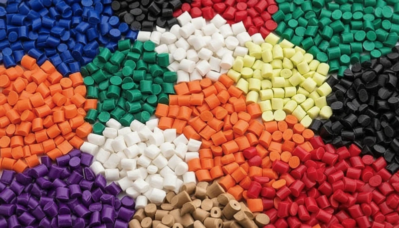
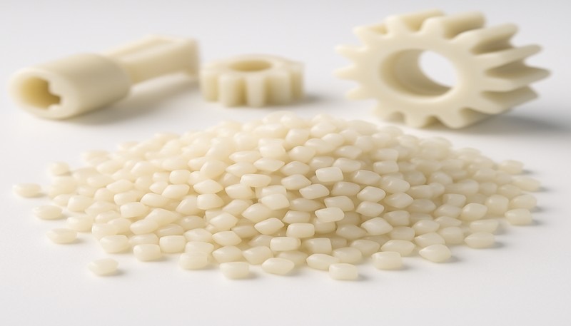
Il policarbonato (PC) è uno dei termoplastici tecnici più versatili nello stampaggio a iniezione: trasparente, resistente agli urti e stabile al calore. Tuttavia, chi lo ha lavorato su una linea produttiva sa che è anche uno dei materiali più difficili da processare. L’elevata viscosità del fuso, l’estrema sensibilità all’umidità e la tendenza ad accumulare tensioni interne fanno sì che anche piccole deviazioni di processo possano produrre difetti visibili: scolorimento, striature argentate, bolle, segni di flusso e cricche da tensione.
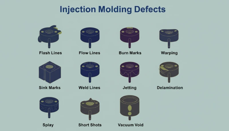
In questo articolo esaminiamo i sei difetti più comuni riscontrati nello stampaggio del PC: scolorimento e punti neri, striature argentate e bolle, segni di flusso, punti di materiale freddo e cricche interne da tensione. Per ogni difetto spieghiamo il meccanismo fisico, come diagnosticarlo dal suo andamento e quali regolazioni specifiche di processo e attrezzatura lo risolvono. Queste indicazioni derivano da vent’anni di esperienza pratica nello stampaggio del PC per applicazioni automobilistiche, medicali e di elettronica di consumo.
- La sensibilità del PC all'umidità (richiede <0.02% di umidità) è la causa principale della maggior parte dei difetti superficiali
- La viscosità del fuso superiore rispetto ad ABS o PP impone per il PC un controllo preciso di temperatura e pressione
- Le tensioni interne nei pezzi trasparenti in PC possono causare cricche ritardate giorni dopo lo stampaggio
- La maggior parte dei difetti ha soluzioni comuni: corretta essiccazione, temperatura del cilindro ottimizzata e adeguato sfiato dello stampo
- L'esperienza di fabbrica con oltre 400 materiali dimostra che la sola disciplina di essiccazione elimina il 60% dei difetti del PC
Perché lo stampaggio a iniezione del policarbonato è così impegnativo?
Il policarbonato è uno dei termoplastici tecnici più difficili da stampare a iniezione. La sua particolare struttura molecolare — catene lineari con anelli benzenici, gruppi isopropilidenici e legami carbonato — crea tre principali difficoltà di lavorazione che lo distinguono da materiali più semplici come il polipropilene o l’ABS.
Se stai confrontando fornitori o pianificando gli acquisti, la nostra guida alla selezione dei fornitori di stampaggio a iniezione tratta la preparazione delle richieste di offerta, la qualificazione e i controlli sui rischi commerciali.
In primo luogo, il PC non ha un punto di fusione netto, ma si ammorbidisce gradualmente in un ampio intervallo di temperatura (230-320 °C); per questo la viscosità del fuso rimane elevata1 durante la normale lavorazione. Diversamente dai polimeri semicristallini, che diventano molto più fluidi oltre il punto di fusione, il PC si comporta più come un fluido newtoniano: la sua viscosità è più sensibile alla temperatura che alla velocità di taglio. Scostamenti di appena 10-15 °C possono trasformare un fuso lavorabile in materiale degradato.
In secondo luogo, il PC è estremamente sensibile all’umidità. Anche tracce d’acqua superiori allo 0.02% in peso causano degradazione idrolitica alle temperature di lavorazione, spezzando le catene polimeriche e riducendo le proprietà meccaniche. È quindi obbligatoria un’accurata preessiccazione a 120 °C per 3–4 ore. Nella nostra esperienza con oltre 400 materiali nello stabilimento di Shanghai, i difetti da umidità rappresentano circa il 60% dei problemi di stampaggio del PC analizzati.
Nella nostra fabbrica di Shanghai, con oltre 20 anni di esperienza nello stampaggio a iniezione di oltre 400 materiali plastici, abbiamo osservato ogni possibile tipologia di difetto del PC. Il controllo dell'umidità e la disciplina nella gestione della temperatura del cilindro sono le due variabili che distinguono una produzione di PC regolare da un costoso evento di scarto.
In terzo luogo, l’elevata viscosità del PC fuso impone uno stampo progettato per pressioni di iniezione maggiori, punti di iniezione e canali più grandi e scanalature di sfiato più profonde rispetto alle plastiche di largo consumo. Canali di flusso sottodimensionati generano calore eccessivo per taglio, causando paradossalmente degradazione termica anche con temperature del cilindro corrette. Comprendere questi tre vincoli, elevata viscosità, sensibilità all’umidità e sensibilità al taglio, è la base per prevenire tutti i difetti trattati nell’articolo.
Quali sono le cause di scolorimento, ingiallimento e punti neri nei componenti in PC?
L’alterazione cromatica è il difetto visivo più comune nello stampaggio a iniezione del PC ed è causata dalla degradazione termica del fuso. La causa principale è generalmente una temperatura eccessiva del cilindro, un tempo di permanenza troppo lungo o zone morte nel sistema di plastificazione, dove il materiale degradato si accumula e viene rilasciato a intermittenza nel flusso del fuso.
La resina PC pura presenta un’eccellente stabilità termica e può tollerare temperature fino a 300 °C senza subire una decomposizione significativa. Il problema si manifesta quando si utilizzano blend di PC modificato, materiale riciclato o compound di PC con ritardanti di fiamma e cariche. Questi additivi restringono notevolmente la finestra di processo. Ad esempio, i blend PC/ABS richiedono in genere temperature del cilindro di circa 250 °C, mentre i blend PC/PBT per prodotti di illuminazione necessitano di circa 280 °C: ogni combinazione ha un proprio limite termico che, una volta superato, provoca ingiallimento o carbonizzazione irreversibili.
I punti neri intermittenti indicano quasi sempre materiale fermo nel sistema: anello di ritegno, interfaccia ugello o rigature cilindro. Carbonizza e si stacca. Oltre una soglia, i prodotti di decomposizione del PC catalizzano altro degrado, soprattutto nei gradi ignifughi.
| Tipo di materiale PC | Temperatura del cilindro consigliata | Rischio di degradazione oltre |
|---|---|---|
| PC puro (grado ottico) | 270-300 C | 320 C |
| Miscela PC/ABS | 240-260 C | 280 C |
| PC con ritardante di fiamma | 230-260 C | 280 C |
| Miscela PC/PBT (illuminazione) | 260-280 C | 300 C |
| PC riciclato | 240-270 C | 290 C (variabile) |
Le soluzioni sono sistematiche. Per prima cosa, confrontare le temperature impostate del cilindro con il grado del materiale e ridurre quelle delle zone di alimentazione e compressione a incrementi di 5-10 °C finché lo scolorimento scompare. In secondo luogo, assicurare un’essiccazione completa: 120 °C per 3-4 ore con un essiccatore deumidificante, senza superare 10 ore per evitare l’invecchiamento del materiale. In terzo luogo, ispezionare il sistema di plastificazione per individuare zone morte: se il fuso estruso a vuoto è scolorito nonostante le temperature corrette, smontare e pulire ugello, valvola di non ritorno e vite. Infine, spurgare il cilindro con un materiale termicamente stabile (PS o PE) prima e dopo ogni ciclo produttivo e non lasciare mai il PC alla temperatura di processo durante soste prolungate; per il mantenimento termico abbassare il cilindro a 160 °C, ossia alla transizione vetrosa del PC2, o meno.
"Abbassare la temperatura del cilindro è sempre il primo intervento quando i pezzi in PC presentano ingiallimento."True
Ridurre la temperatura del cilindro è la prima risposta corretta, perché il calore eccessivo è la causa più comune dell'ingiallimento del PC. Tuttavia, se lo scolorimento persiste dopo una riduzione di 10-15 C, la causa principale è probabilmente materiale ristagnante nel sistema di plastificazione o materia prima contaminata.
"L'impiego di una contropressione più elevata migliora sempre la qualità del fuso di PC."False
Una contropressione eccessiva genera ulteriore calore di taglio nel cilindro, che può accelerare la degradazione termica del PC. L'approccio corretto consiste in una contropressione moderata (0.5-1.5 MPa), abbinata a un'essiccazione adeguata e a un profilo corretto della temperatura del cilindro.
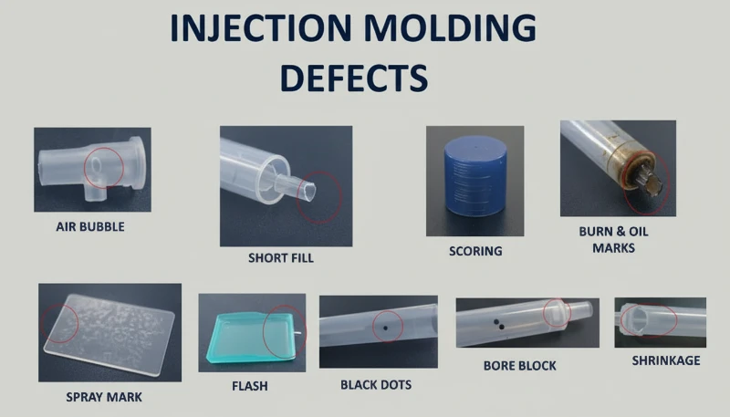
Perché sui prodotti in PC compaiono striature argentate e bolle?
Le striature argentate (dette anche striature da gas) e le bolle sono difetti superficiali e interni causati dal gas intrappolato nel fuso durante il riempimento della cavità. Nello stampaggio a iniezione del PC, le quattro fonti di gas sono il vapore acqueo, l’aria inglobata, i gas di decomposizione termica e i vapori di solvente; il vapore acqueo e i gas di decomposizione rappresentano la grande maggioranza dei casi.
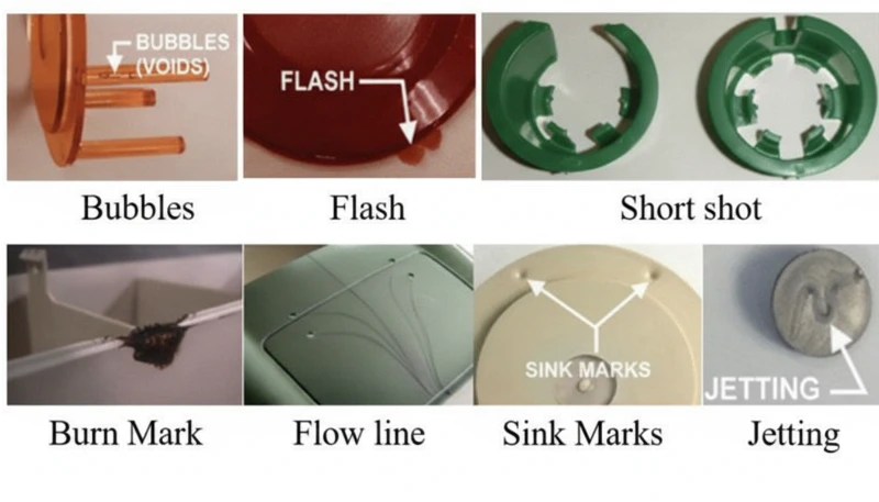
Le striature argentate si formano quando il gas disciolto nel fuso pressurizzato fuoriesce verso la superficie del prodotto mentre la pressione in cavità diminuisce dopo il riempimento. Il gas in fuga lascia minuscole bolle allungate che brillano alla luce, sempre allineate nella direzione del flusso del materiale. Le bolle, invece, sono sacche di gas intrappolate nello spessore della parete, particolarmente visibili nei componenti trasparenti in PC. Le bolle da vuoto sono diverse: non sono generate dal gas, ma dal ritiro volumetrico quando una pressione di mantenimento insufficiente lascia un vuoto nelle sezioni spesse.
Come diagnosticare la fonte del gas responsabile delle striature argentate
Per individuare il gas responsabile occorre interpretare la configurazione del difetto. Bolle superficiali distribuite casualmente indicano vapore acqueo, la causa più comune nel PC a causa dell’elevata igroscopicità del materiale. Aggregati fini e densi di bolle, concentrati vicino al punto di iniezione secondo una disposizione radiale o a ventaglio, indicano aria intrappolata, generalmente dovuta a una velocità eccessiva di arretramento della vite o a una contropressione insufficiente. La presenza di scolorimento insieme alle striature argentate indica gas di decomposizione generato dal surriscaldamento del fuso. Il processo diagnostico è fondamentale, poiché ogni origine del gas richiede un intervento diverso.
Per le striature argentate causate dall’umidità, la soluzione è semplice: garantire l’essiccazione a 120 °C per 3–4 ore con un essiccatore deumidificante. Verificarne l’efficacia mediante spurgo in aria: il fuso estruso deve essere continuo, liscio e privo di vapore bianco. In caso di intrappolamento d’aria, ridurre la velocità della vite, aumentare la contropressione e prolungare il tempo di plastificazione durante la fase di raffreddamento. In caso di gas da decomposizione, abbassare la temperatura del cilindro sezione per sezione iniziando dall’ugello e verificare che i tempi di permanenza non siano eccessivamente lunghi (l’impiego di macchine sovradimensionate per pezzi piccoli è una causa comune).
Le bolle da vuoto richiedono un approccio diverso, perché sono dovute al ritiro e non al gas. Aumentare la pressione e prolungare il tempo di mantenimento per compattare più materiale nella sezione spessa. Posizionare il punto di iniezione sulla parete più spessa per assicurare la trasmissione della pressione. Aumentare localmente la temperatura dello stampo in corrispondenza del vuoto per rallentare la solidificazione e compensare il ritiro. Per i prodotti trasparenti, anche un raffreddamento lento in acqua calda dopo lo stampaggio può ridurre la formazione di bolle da vuoto.
"Un trattamento termico post-stampaggio a 120 C per 2 ore può ridurre significativamente le tensioni interne nei pezzi in PC."True
Il trattamento termico a circa 120 C consente ai segmenti delle catene molecolari del PC di riacquistare mobilità e rilassare la deformazione elastica congelata. Le molecole orientate tornano verso uno stato disordinato, riducendo sia le tensioni da orientamento sia quelle termiche. È una pratica standard per le applicazioni ottiche in PC e per quelle critiche sotto il profilo delle tensioni.
"Le bolle da vuoto nei componenti in PC sono causate da aria intrappolata."False
Le bolle da vuoto sono in realtà causate dal ritiro volumetrico durante il raffreddamento, non da aria intrappolata. Quando la pressione di mantenimento è insufficiente o il punto di iniezione solidifica troppo presto, il nucleo ancora fuso si ritira separandosi dalla pelle già solidificata e crea un vuoto. La soluzione consiste nell'aumentare pressione e tempo di mantenimento, non lo sfiato.
Che cosa sono le impronte digitali e le linee di turbolenza e come si eliminano?
Le impronte e le linee di turbolenza sono difetti di flusso causati da una viscosità del fuso di PC troppo elevata rispetto alla velocità di iniezione e alla temperatura dello stampo. Il fuso riempie la cavità con un moto intermittente, lasciando linee ondulate perpendicolari alla direzione del flusso (impronte) o striature radiali vicino al punto di iniezione (turbolenza).
I segni a impronta digitale si sviluppano quando la velocità e la pressione di iniezione sono troppo basse rispetto alla viscosità del fuso. Il fronte del flusso entra in contatto con la parete fredda dello stampo, solidifica e si ritira. Il fuso caldo retrostante spinge in avanti la pelle ritirata, quindi anche quello strato si raffredda e si ritira. Questo ciclo alternato di avanzamento e congelamento crea il caratteristico motivo ondulato simile a un’impronta digitale. L’effetto è più visibile sulle grandi superfici piane in PC, come coperture per display o pannelli di controllo.
I segni di turbolenza sono correlati ma distinti. Si presentano come linee di flusso irregolari che si irradiano dal punto di iniezione, causate dal fuso che colpisce ad alta velocità la parete della cavità e scivola sulla superficie fredda prima di stabilizzarsi in un flusso laminare. Il difetto è particolarmente comune quando il punto di iniezione crea una brusca transizione di velocità, per esempio un punto piccolo che alimenta una cavità grande e spessa. La distinzione fondamentale: le impronte sono perpendicolari al flusso, mentre le linee di turbolenza sono parallele.
Entrambi i difetti condividono le stesse soluzioni. Aumenta le temperature dell’ugello e della zona anteriore del cilindro per ridurre la viscosità del fuso: è la regolazione più efficace. Aumenta la temperatura dello stampo, soprattutto nel punto in cui compaiono i segni; per i pezzi in PC con requisiti estetici, è prassi impostare il termoregolatore dello stampo a 100–120 °C. Aumenta la velocità di iniezione per passare da un riempimento intermittente a uno continuo; l’iniezione multistadio consente di regolare la velocità sezione per sezione, intervenendo sull’area problematica senza causare bave altrove. Sul lato stampo, amplia punti di iniezione e canali per ridurre la resistenza al flusso e garantisci uno sfiato adeguato e pozzetti per la materozza fredda.
Con 47 presse a iniezione da 90T a 1850T e la simulazione MOLDFLOW per ottimizzare punti di iniezione e canali, risolviamo generalmente i problemi dei segni di flusso nella fase DFM, prima ancora di lavorare l'acciaio. La simulazione individua le transizioni di velocità che causano segni di turbolenza, consentendo di riprogettare il punto di iniezione prima di realizzare lo stampo.
Come si formano le zone di materiale freddo e come si possono prevenire?
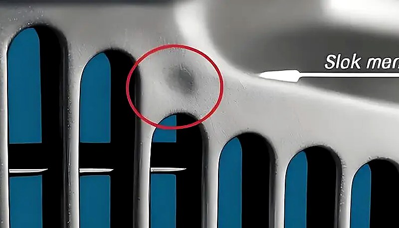
Le macchie di materiale freddo sono segni opachi, lucidi o vermiformi vicino al punto di iniezione, causati dall’ingresso in cavità di fuso parzialmente solidificato. Si formano quando il fronte di flusso perde troppo calore sulla punta dell’ugello, nel canale o nel punto di iniezione prima del riempimento, oppure quando una pressione di mantenimento eccessiva spinge nel pezzo materiale già raffreddato del canale.
Esistono due meccanismi distinti. Il primo è il materiale freddo anteriore: tra le iniezioni, il fuso sulla punta dell’ugello e all’ingresso del canale si raffredda perché l’ugello tocca la piastra fredda dello stampo. All’inizio dell’iniezione questo materiale raffreddato entra per primo nella cavità. Sui pezzi a parete sottile si diffonde in chiazze torbide, fumose o pastose; su quelli a parete spessa forma una cicatrice curva simile a un lombrico. Il secondo è il materiale freddo da contropressione: tempo e pressione di mantenimento eccessivi spingono nel pezzo il materiale già raffreddato dal canale e dal punto d’iniezione, creando una piccola macchia circolare lucida vicino al punto d’iniezione.
La prevenzione è semplice, ma richiede attenzione ai dettagli. Installare un pozzetto per la materozza fredda alla fine di ciascun canale di colata: in questo modo il materiale freddo all’avanzamento viene trattenuto prima di entrare nella cavità. Aumentare la temperatura dell’ugello per ridurre la perdita di calore in punta. Aumentare la temperatura dello stampo per ridurre la differenza tra le temperature del fuso e della superficie dello stampo. Ridurre la velocità di iniezione all’inizio del riempimento per evitare la frattura del fuso al punto di iniezione, quindi aumentarla durante il riempimento principale. Ottimizzare posizione, dimensioni e forma del punto di iniezione per evitare brusche variazioni di velocità. In presenza di zone fredde durante la pressione di mantenimento, ridurre il tempo di mantenimento e la relativa pressione al minimo necessario per la stabilità dimensionale. Assicurare inoltre un’essiccazione completa del materiale: l’umidità residua nella materozza fredda può aggravare il difetto visivo.
Perché le tensioni interne provocano cricche nei prodotti trasparenti in PC?
Le tensioni interne nei prodotti in PC sono dovute all’orientamento molecolare congelato e a tensioni di raffreddamento non uniformi. Possono causare deformazione, minore trasparenza ottica e criccatura ritardata dopo giorni o settimane dallo stampaggio: i pezzi trasparenti in PC sono il segnale d’allarme precoce.
Due meccanismi principali generano tensioni interne. La tensione da orientamento deriva dalle catene polimeriche allungate durante il flusso e congelate in posizione prima di poter tornare a una configurazione a gomitolo casuale. Pressione di iniezione più elevata, velocità di iniezione maggiore e tempo di mantenimento più lungo aumentano l’orientamento, applicando più taglio al fuso. La tensione termica deriva dall’ampia differenza di temperatura tra il nucleo caldo del fuso e la parete fredda dello stampo. Poiché il PC presenta elevato calore specifico e bassa conducibilità termica, la superficie solidifica molto prima dell’interno, creando tensione di compressione all’esterno e tensione di trazione all’interno.
La conseguenza pratica è che un pezzo in PC può apparire perfetto subito dopo lo stampaggio ma sviluppare microcricche entro pochi giorni, soprattutto se esposto a solventi organici (detergenti, adesivi) o temperature elevate. In produzione abbiamo visto lenti trasparenti in PC incrinarsi durante l’assemblaggio solo perché l’operatore aveva usato una salvietta a base alcolica: la tensione interna era già alla soglia di rottura e il solvente l’ha abbassata quanto bastava per innescare la cricca.
Il nostro reparto interno di costruzione stampi (oltre 100 stampi al mese) ci consente di ottimizzare posizione del punto di iniezione, geometria dei canali e disposizione dei circuiti di raffreddamento specificamente per componenti in PC sensibili alle tensioni. Insieme ai sistemi qualità ISO 9001 e ISO 13485, individuiamo le tensioni interne durante il controllo del primo articolo mediante analisi a luce polarizzata.
"L'analisi con luce polarizzata può rilevare le tensioni interne nei pezzi trasparenti in PC prima che si incrinino."True
Sotto luce polarizzata, il PC tensionato mostra figure di birifrangenza che rivelano orientamento molecolare congelato e tensioni da raffreddamento non uniformi. Questo metodo non distruttivo consente alle fabbriche di individuare problemi di tensione durante l'ispezione del primo articolo, molto prima che i pezzi cedano in servizio.
"La ricottura post-stampaggio a 120 C riduce le tensioni interne nei pezzi trasparenti in PC."False
La ricottura a 120 C riduce effettivamente le tensioni interne, consentendo alle catene molecolari di rilassarsi. Tuttavia, non sostituisce parametri di stampaggio corretti: può soltanto ridurre le tensioni generate, non eliminarle completamente. L'approccio più efficace consiste nel minimizzare le tensioni durante lo stampaggio mediante impostazioni corrette di temperatura e pressione, per poi utilizzare la ricottura come fase finale di assicurazione qualità per i componenti critici.
Per ridurre le tensioni interne è necessario un approccio complessivo. Aumentare la temperatura del fuso per ridurre la viscosità e l’orientamento durante il flusso. Aumentare la temperatura dello stampo per ottenere un raffreddamento più lento e uniforme e lasciare alle molecole orientate il tempo di rilassarsi. Ridurre la pressione d’iniezione al minimo necessario per il riempimento completo. Ridurre al minimo il tempo di mantenimento: il sovrariempimento è una delle principali cause delle tensioni da orientamento. Utilizzare un’iniezione a velocità variabile: riempimento rapido per evitare difetti di flusso, quindi velocità ridotta durante il mantenimento per limitare l’allineamento molecolare. Per i pezzi con inserti metallici, preriscaldare gli inserti a circa 200 °C per ridurre lo sbilanciamento termico. Infine, un trattamento termico post-stampaggio a 120 °C per circa 2 ore consente ai segmenti delle catene polimeriche di recuperare mobilità e rilassare la deformazione congelata; questa è una pratica standard per i componenti in PC di grado ottico.
"Ridurre la pressione di iniezione al minimo necessario per riempire la cavità aiuta a prevenire le tensioni interne nei pezzi in PC."True
Una pressione di iniezione eccessiva aumenta l'orientamento molecolare e la sollecitazione di taglio, incrementando le tensioni interne e il rischio di deformazione e criccatura sotto sforzo. La pressione minima che consente il riempimento completo, abbinata a un'adeguata temperatura del fuso, produce pezzi in PC con le tensioni più basse.
"L'aumento della temperatura dello stampo oltre 100 °C migliora sempre la finitura superficiale dei componenti in PC."False
Sebbene una temperatura dello stampo più elevata possa ridurre i segni di flusso e migliorare la brillantezza superficiale, superare 100 °C per cicli prolungati può causare tempi di raffreddamento eccessivamente lunghi e portare alla degradazione termica della resina PC in prossimità del punto di iniezione. L'intervallo ottimale di temperatura dello stampo per il PC è in genere 80–100 °C e bilancia la qualità della finitura con l'efficienza del ciclo e la stabilità del pezzo.
Quali parametri di processo monitorare per ridurre al minimo i difetti del PC?
Sei parametri sono fondamentali per prevenire i difetti del PC: essiccazione, temperatura del cilindro, velocità di iniezione, pressione di mantenimento e temperatura dello stampo. Impostarli correttamente elimina la grande maggioranza dei problemi di scolorimento, striature argentate, bolle, segni di flusso e tensioni interne.
L’essiccazione è imprescindibile. Il PC richiede un contenuto di umidità inferiore allo 0,02%3, ottenibile con un essiccatore deumidificante a 120 °C per 3-4 ore. Superare 10 ore espone il materiale al rischio di degradazione, soprattutto nei gradi ritardanti di fiamma. Prima di avviare la produzione, verificare l’efficacia dell’essiccazione osservando il materiale estruso a vuoto. Questo solo passaggio previene la maggior parte delle striature argentate e delle bolle superficiali.
La temperatura del cilindro deve essere impostata come profilo, non come valore singolo. Per il PC puro, un profilo tipico è 250 °C (alimentazione) → 270 °C (compressione) → 285 °C (dosaggio) → 290 °C (ugello). Ogni grado modificato ha una propria finestra: PC/ABS a circa 20 °C in meno, PC/PBT a temperature simili o leggermente superiori. Occorre partire dal limite inferiore dell’intervallo raccomandato e aumentare solo se compaiono segni di flusso o riempimenti incompleti. Non impostare mai tutte le zone alla stessa temperatura; un gradiente corretto garantisce una plastificazione graduale senza fusione prematura nella zona di alimentazione, che impedirebbe la fuoriuscita dell’aria, né preriscaldamento insufficiente, che intrappolerebbe aria nel fuso.
| Parametro | Intervallo consigliato (PC puro) | Difetti prevenuti |
|---|---|---|
| Temperatura di essiccazione | 120 C, 3-4 h, deumidificato | Striature argentate, bolle superficiali |
| Temperatura cilindro (ugello) | 280-295 C | Riempimenti incompleti, segni di flusso |
| Temperatura dello stampo | 80-120 C | Impronte digitali, tensioni interne |
| Velocità di iniezione | Multistadio: riempimento rapido, compattazione lenta | Segni di turbolenza, sovracompressione |
| Pressione di mantenimento | 60-80% di pressione di iniezione | Bolle di vuoto, segni di affondamento |
| Tempo di mantenimento | Fino al congelamento del punto di iniezione (3-8 s) | Cavità da ritiro, deriva dimensionale |
Il tempo di permanenza del fuso merita un’attenzione particolare. Utilizzare attrezzature sovradimensionate per piccoli pezzi in PC è un errore comune—l’elevato rapporto peso colpo/capacità della canna significa che il materiale rimane alla temperatura di processo troppo a lungo, accumulando danni termici. Come regola generale, il peso della dose dovrebbe essere almeno del 30–40% della capacità della canna. Se devi produrre piccoli pezzi su macchine grandi, usa una vite di diametro inferiore o accetta che frequenti spurghi e cambi colore siano inevitabili. Infine, la temperatura dello stampo è più importante per il PC che per la maggior parte delle materie plastiche. Lavorare con stampi freddi (sotto gli 80 °C) accelera la solidificazione della pelle, aumenta lo stress interno e amplifica le striature di flusso. Per pezzi trasparenti o critici per l’aspetto, una temperatura dello stampo di 100–120 °C con un controllore di temperatura è lo standard del settore.
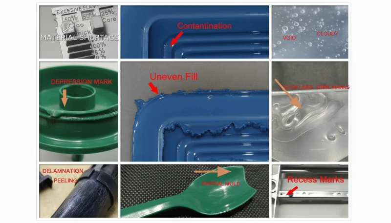
Quali Sono le Domande Più Comuni sui Difetti di Stampa a Iniezione in PC?
Domande frequenti
Qual è la temperatura ideale di essiccazione per il policarbonato prima della stampa a iniezione?
Il policarbonato deve essere essiccato a 120 °C utilizzando un essiccatore deumidificante per 3-4 ore per ottenere un contenuto di umidità inferiore allo 0.02% prima della stampa a iniezione. Questo è un requisito non negoziabile per una lavorazione di successo del PC—saltare o ridurre la fase di essiccazione è la causa più comune di difetti superficiali. L’essiccazione oltre le 10 ore rischia di degradare il materiale, soprattutto per le qualità ritardanti di fiamma che sono più sensibili al calore. Verificare sempre l’efficacia con un test di estrusione in aria prima dell’inizio della produzione—il fuso estruso deve essere continuo, liscio e privo di vapore bianco. Utilizzare un normale essiccatore tramoggia senza deumidificazione è insufficiente per il PC.
Cosa causa le macchie nere nei componenti stampati a iniezione in policarbonato?
Le macchie nere nei pezzi stampati a iniezione in PC sono tipicamente causate da materiale carbonizzato intrappolato nelle zone morte del sistema di plastificazione—come i giochi dell’anello di ritegno della vite, le interfacce della punta dell’ugello o i graffi sulla parete della canna. Il materiale intrappolato si degrada nel tempo e si stacca in modo intermittente nel flusso di fuso, producendo macchie scure che appaiono casualmente su diverse iniezioni per poi scomparire. Lo smontaggio e la pulizia regolari del sistema di plastificazione, combinati con una corretta procedura di spurgo della canna utilizzando PS o PE prima e dopo ogni ciclo di produzione, prevengono efficacemente questo problema. Non lasciare mai il materiale PC alla temperatura di processo durante fermate prolungate della macchina.
Qual è la temperatura di stampa a iniezione raccomandata per il policarbonato?
Per il policarbonato puro, il profilo di temperatura raccomandato per la canna è 250 °C (zona alimentazione) a 285-295 °C (ugello), con temperatura dello stampo a 80-120 °C. La chiave è utilizzare un gradiente di temperatura tra le zone piuttosto che un singolo setpoint, garantendo una plastificazione graduale senza fusione prematura nella zona di alimentazione. Le qualità modificate hanno finestre diverse: le miscele PC/ABS lavorano circa 20 °C più in basso, mentre le miscele PC/PBT potrebbero richiedere temperature simili o leggermente più alte. Iniziare sempre all’estremità inferiore dell’intervallo raccomandato e aumentare solo se compaiono difetti di flusso.
Come si previene lo stress interno nei prodotti trasparenti in PC?
Prevenire lo stress interno nei pezzi trasparenti in PC richiede un approccio a più fronti. Usare una temperatura di fuso più alta per ridurre la viscosità e l’orientamento molecolare durante il flusso. Aumentare la temperatura dello stampo a 100-120 °C per un raffreddamento più lento e uniforme che dia alle molecole orientate il tempo di rilassarsi. Minimizzare la pressione di iniezione e di mantenimento al minimo necessario per un riempimento completo. Usare un’iniezione a velocità variabile con riempimento rapido seguito da un’imballaggio lento. Il trattamento termico post-stampa a 120 °C per circa 2 ore è la pratica standard per i componenti ottici per rilassare l’orientamento molecolare congelato.
Perché compaiono striature argentate sui pezzi stampati a iniezione in PC?
Le striature argentate sui componenti in PC sono causate dal gas che sfugge sulla superficie del prodotto durante o dopo il riempimento della cavità, lasciando piccole bolle allungate che brillano sotto la luce. La fonte di gas più comune è il vapore acqueo proveniente da materiale non adeguatamente essiccato—questo rappresenta la maggior parte dei casi. Il gas da decomposizione termica dovuto a temperature eccessive della canna è la seconda causa più comune. Strie argentate fini e dense concentrate vicino al punto di iniezione in uno schema radiale indicano aria intrappolata dovuta a velocità della vite eccessiva o pressione di ritorno insufficiente. Un’essiccazione corretta a 120 °C per 3-4 ore elimina la maggior parte dei casi guidati dall’umidità.
È possibile correggere i difetti di stampa a iniezione in policarbonato regolando solo i parametri della macchina?
Molti difetti del PC—in particolare striature argentate, scolorimento e segni di flusso—possono essere risolti solo attraverso aggiustamenti dei parametri della macchina, principalmente condizioni di essiccazione, profilatura della temperatura della canna e ottimizzazione della velocità di iniezione. Tuttavia, difetti ricorrenti come macchie persistenti di materiale freddo o segni di turbolenza spesso richiedono modifiche allo stampo come punti di iniezione ingranditi, canali di sfiato aggiuntivi o pozzetti per colate fredde. La riduzione dello stress interno può anche richiedere cambiamenti progettuali per l’uniformità dello spessore della paretta e il preriscaldamento degli inserti. L’approccio più efficace combina l’ottimizzazione dei parametri con un corretto design dello stampo fin dall’inizio.
Qual è la differenza tra bolle e bolle da vuoto nei pezzi in PC?
Le bolle nei pezzi in PC sono cavità riempite di gas causate da vapore acqueo, aria inglobata o gas da decomposizione termica intrappolati durante il riempimento dello stampo. Sono presenti immediatamente all’apertura dello stampo e non crescono nel tempo. Le bolle da vuoto sono fondamentalmente diverse—sono cavità indotte da ritiro che si formano durante il raffreddamento quando la pressione di mantenimento è insufficiente a compensare il ritiro volumetrico nelle sezioni spesse. Le bolle da vuoto possono apparire o ingrandirsi dopo lo sformaggio man mano che l’interno continua a raffreddarsi e contrarsi. La differenza diagnostica determina se affrontare il contenuto di gas attraverso essiccazione e temperatura, o l’imballaggio attraverso la pressione di mantenimento.
Come Puoi Ottenere Supporto Esperto per il Tuo Progetto di Stampa a Iniezione in PC?
ZetarMold è il partner produttivo per progetti di stampaggio a iniezione in policarbonato che richiedono zero difetti. Il nostro team di ingegneria porta oltre 20 anni di esperienza nella lavorazione del PC e oltre 400 materiali in ogni progetto, dall’essiccazione del materiale e la profilatura della temperatura al design del punto di iniezione e la riduzione degli stress. La nostra struttura interna per gli stampi, la capacità di simulazione MOLDFLOW e i sistemi di qualità certificati ISO significano che i vostri componenti in PC sono progettati per la qualità fin dalla fase di DFM.
Ti serve un preventivo per un progetto di stampaggio a iniezione del policarbonato? Richiedi al nostro team tecnico prezzi competitivi, riscontri DFM e tempi di produzione. Richiedi oggi un preventivo gratuito oppure consulta la nostra Guida completa allo stampaggio a iniezione per una panoramica esaustiva del processo.
la viscosità del fuso rimane elevata: significa che la viscosità del PC fuso è più sensibile alle variazioni di temperatura che alla velocità di taglio e durante la lavorazione presenta un comportamento simile a quello di un fluido newtoniano. ↩
transizione vetrosa del PC: il policarbonato ha una temperatura di transizione vetrosa (Tg) di circa 147-150 °C, che determina la temperatura minima per il mantenimento termico. ↩
contenuto di umidità inferiore allo 0,02%: prima della lavorazione il PC deve avere un contenuto di umidità inferiore allo 0,02% (200 ppm), per evitare la degradazione idrolitica alle temperature di stampaggio. ↩