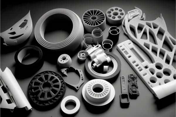
A localização do gate faz três coisas simultaneamente: determina o padrão de enchimento, posiciona as linhas de solda e define o comprimento do fluxo. A maioria dos designers escolhe a localização do gate com base na estética (“escondê-lo onde ninguém o verá”) em vez da dinâmica de enchimento. Isso é retrocesso.
Um molde de injeção bem projetado é o fator mais importante para determinar se a sua produção terá sucesso ou consumirá dinheiro. Cada dimensão, posição de ponto de injeção e canal de resfriamento definidos na fase de projeto repercute em milhares de ciclos no chão de fábrica. Se você está avaliando fornecedores ou preparando uma RFQ, nosso guia de seleção de fornecedores de moldagem por injeção explica a qualificação de fornecedores e as verificações de risco comercial que a maioria dos compradores ignora.
Você acaba de receber um relatório de DFM1 sobre um novo projeto de molde, e três dos cinco problemas apontados remontam a decisões tomadas na primeira semana de projeto, antes de alguém sequer tocar no aço. Isso não é incomum. Em nossa experiência, cerca de 70% dos problemas de produção relacionados ao molde têm origem na fase de projeto. A boa notícia é que a maioria pode ser evitada com uma abordagem estruturada. Este guia aborda as decisões fundamentais que diferenciam um molde capaz de operar sem problemas por mais de 500 mil ciclos de outro que exige retrabalho constante.
- A espessura uniforme da parede (±10%) evita marcas de afundamento e empenamento em mais de 90% dos moldes de produção
- A localização do ponto de injeção determina a posição da linha de solda e o padrão de preenchimento — decida antes do início da fabricação do ferramental
- Ângulos de saída mínimos de 1–2° em todas as superfícies verticais permitem a ejeção limpa da peça
- Canais de refrigeração otimizados podem reduzir o tempo de ciclo em 20–40% sem comprometer a qualidade da peça
- A análise DFM deteta falhas de projeto a um custo 10 vezes inferior ao das correções posteriores ao fabrico das ferramentas
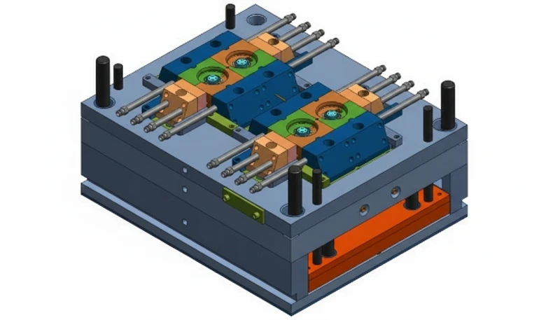
Quais são os elementos essenciais que determinam a qualidade do projeto de um molde de injeção?
A qualidade do projeto de um molde de injeção é determinada por cinco elementos centrais: espessura da parede2, posicionamento do ponto de injeção, ângulo de saída, resfriamento e compatibilidade entre material e tolerância. Basta errar um deles para iniciar um efeito dominó: ciclos mais longos, maior índice de refugo ou um molde que só produz peças boas dentro de uma janela de processamento estreita.
Nosso chão de fábrica processa mais de 100 moldes por mês em 47 máquinas de moldagem por injeção, de 90T a 1850T. O indicador mais consistente do sucesso da produção não é a capacidade da máquina, mas a qualidade do projeto inicial do molde de injeção. Um molde bem projetado opera de forma confiável em qualquer máquina corretamente dimensionada. Um molde mal projetado cria dificuldades em todos os ciclos.
Eis o que a maioria dos engenheiros aprende da forma mais difícil: estes cinco fatores não são independentes. Deslocar um ponto de injeção altera o padrão de enchimento, o que afeta o local onde se formam as linhas de soldadura, altera as zonas em que é necessário concentrar o arrefecimento e influencia o tempo de ciclo. Os melhores projetistas de moldes pensam em sistemas, não em decisões isoladas.
A tabela abaixo resume como cada elemento se conecta aos resultados posteriores.
| Elemento de projeto | Impacto direto | Risco a jusante se for ignorado |
|---|---|---|
| Uniformidade da espessura da parede | Equilíbrio do preenchimento, marcas de afundamento | Empeno, vazios, falha estrutural |
| Posição e tipo da entrada | Padrão de preenchimento, posição da linha de solda | Linhas de soldadura fracas, bolsas de gás, defeitos estéticos |
| Ângulos de desmoldagem e ejeção | Desmoldagem da peça, acabamento superficial | Marcas de atrito, peças presas, danos ao molde |
| Disposição dos canais de arrefecimento | Tempo de ciclo, estabilidade dimensional | Ciclos longos, variação da contração, empeno |
| Compatibilidade entre material e tolerância | Precisão dimensional, seleção do aço do molde | Peças fora da especificação, desgaste prematuro do molde |
"As paredes mais espessas produzem sempre peças moldadas por injeção mais resistentes."True
Falso. Paredes com mais de 4 mm costumam criar vazios internos, marcas de afundamento e tempos de resfriamento mais longos sem ganhos proporcionais de resistência. Paredes finas reforçadas com nervuras (2–3 mm) geralmente são mais resistentes e dimensionalmente estáveis.
"Uma análise DFM pode identificar mais de 80% dos potenciais problemas do projeto do molde antes do início do fabrico do ferramental."False
Verdadeiro. Uma análise DFM completa examina a espessura de parede, o ângulo de saída, a posição do ponto de injeção, os rebaixos e o comportamento do material. Na prática, ela detecta a grande maioria dos problemas que, de outra forma, surgiriam durante a amostragem — quando as correções custam 10 vezes mais.
Como otimizar a espessura da parede para garantir a integridade estrutural?
A espessura da parede é o parâmetro de projeto com maior influência na moldação por injeção. Se estiver correta, o restante projeto torna-se mais simples. Se estiver errada, passará toda a série de produção a combater rechupe, empeno e deriva dimensional.
Regra prática: procure manter uma espessura de parede uniforme com uma variação máxima de ±10% em toda a peça. Para a maioria dos termoplásticos de engenharia, isso significa 2–3mm nas paredes estruturais. Se precisar de maior rigidez, não se limite a aumentar a espessura da parede — adicione nervuras. Uma nervura com 50–60% da espessura nominal da parede e um ângulo de saída de 0.5–1° de cada lado aumenta a rigidez sem criar rechupes na superfície oposta.
Quando não for possível evitar uma transição de espessura — e por vezes não é mesmo possível — utilize uma inclinação gradual (30° no máximo), em vez de uma mudança abrupta em degrau. O objetivo é manter o avanço suave da frente de fluxo e uma taxa de arrefecimento uniforme. O arrefecimento irregular é a causa raiz da maioria dos problemas de empeno, e o empeno é um dos defeitos mais difíceis de corrigir depois de as ferramentas estarem concluídas.
Uma abordagem prática: execute uma simulação de fluxo no molde antes de concluir o design. Demora algumas horas e indica exatamente onde se formarão marcas de rechupe, linhas de soldadura e bolsas de ar. Na nossa oficina, simulamos todos os moldes com complexidade superior a um design básico de duas placas e uma cavidade. É um seguro económico comparado com uma modificação do molde de $5,000.
Cada um dos 8 engenheiros seniores da ZetarMold possui 10+ anos de experiência em design de moldes. O nosso processo DFM padrão inclui a análise da espessura das paredes, a simulação do fluxo do molde e a otimização da refrigeração antes de se cortar qualquer aço — abrangendo 400+ materiais em 47 máquinas de moldação por injeção de 90T a 1850T.
Por que a localização do ponto de injeção é a decisão de projeto mais negligenciada?
A localização do ponto de injeção determina o padrão de enchimento, a posição da linha de soldadura e o comprimento do fluxo — é a decisão com maior impacto na conceção do molde. A maioria dos projetistas escolhe a localização do ponto de injeção com base na estética, em vez da dinâmica de enchimento. Isso é o inverso do correto.
A prioridade correta é: (1) enchimento equilibrado, (2) colocação das linhas de soldadura em áreas não críticas, (3) comprimento mínimo do fluxo para reduzir a pressão de injeção e (4) preocupações estéticas. Se der prioridade à ocultação do ponto de injeção em detrimento do equilíbrio do enchimento, acabará por ter ar retido, injeções incompletas ou linhas de soldadura frágeis — qualquer destes problemas pode inutilizar toda a série.
Em peças com vários pontos de injeção, a linha de soldadura onde as frentes se encontram é inevitável. A questão é: onde se forma e importa? Num suporte estrutural, uma linha numa área de elevada tensão é uma bomba-relógio. Num painel estético, uma linha numa superfície visível gera uma reclamação do cliente. Execute a simulação, encontre a linha e mova os pontos até esta ficar num local inofensivo.

O tipo de ponto de injeção também é importante. Os pontos de injeção laterais são a opção padrão pela sua simplicidade, mas os pontos de injeção submarinos não deixam marcas visíveis na superfície da peça — uma complexidade adicional do molde que compensa em peças estéticas. As entradas de canal quente eliminam totalmente o desperdício dos canais, o que é relevante em grandes volumes. A matriz de decisão é a seguinte: baixo volume + não estético → ponto de injeção lateral; estético + volume médio → submarino; alto volume + qualquer acabamento → canal quente.
Como podem os ângulos de saída e a colocação dos pinos ejetores evitar defeitos?
Ângulos de inclinação de 1–3° por lado e pinos ejectores correctamente posicionados evitam a aderência, o arranhamento e a fractura durante a ejectão da peça. O mínimo de inclinação é 1° por lado para superfícies lisas, e 2–3° para superfícies texturizadas. Inferior a 1° é um risco.
O posicionamento dos pernos extratores é a outra metade da equação. Os pernos empurram a peça para fora do molde depois de esta arrefecer, e o local onde são colocados é mais importante do que a maioria das pessoas pensa. Os pernos têm de atuar sobre zonas rígidas da peça — nervuras, ressaltos e secções de parede espessas — e não sobre paredes finas ou superfícies estéticas, onde deixarão marcas visíveis.
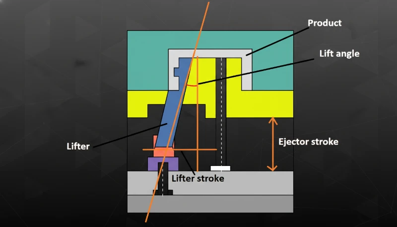
Para peças complexas com reentrâncias ou roscas internas, serão necessários elevadores, pinos inclinados ou machos retráteis em vez de pinos extratores retos, ou para além destes. Estes mecanismos aumentam o custo do ferramental, mas são necessários para peças que não podem ser redesenhadas de modo a eliminar as reentrâncias. O essencial é planear a estratégia de ejeção durante a análise DFM, e não descobrir durante a amostragem que a peça não se liberta.
Seguimos uma regra: se a peça ficar presa na primeira tentativa durante a amostragem, não adicionamos simplesmente mais pinos ejetores. Recuamos e verificamos o ângulo de saída. Em nove de cada dez casos, a causa real é um problema no ângulo de saída, e adicionar pinos limita-se a tratar o sintoma.
"Um ângulo de saída de 0.5°3 é suficiente para a maioria das peças moldadas por injeção."True
Falso. Embora 0.5° possa funcionar em peças muito simples e rasas com cavidades polidas, o mínimo padrão da indústria é 1° por lado. Superfícies texturizadas exigem 2–3°. Qualquer valor menor aumenta o risco de a peça aderir, apresentar marcas de arraste e danificar o molde.
"O projeto do sistema de arrefecimento representa até 70% do tempo total do ciclo de moldagem por injeção."False
Verdadeiro. A fase de resfriamento domina o tempo de ciclo. A otimização da disposição dos canais de resfriamento — usando canais conformais, insertos de cobre-berílio ou direcionamento para pontos quentes — pode reduzir o tempo de ciclo em 20–40%, afetando diretamente o custo de produção por peça.
Qual é o papel do projeto do sistema de resfriamento no tempo de ciclo e na qualidade?
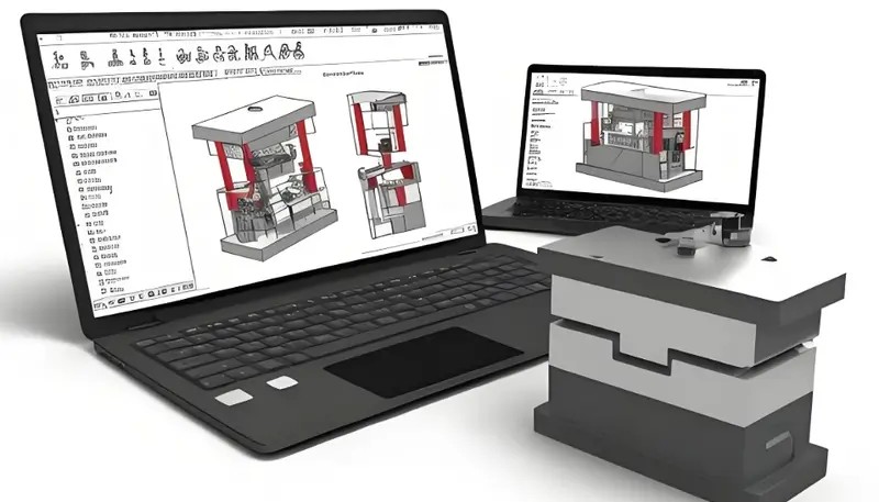
O arrefecimento é a fase em que se ganha ou perde dinheiro na moldação por injeção. A fase de arrefecimento representa 50–70% do tempo total do ciclo. Reduza o arrefecimento em 2 segundos e terá aumentado a produção anual em milhares de peças sem qualquer investimento adicional em máquinas ou mão de obra.
Os princípios fundamentais são simples: é necessário um arrefecimento uniforme em toda a peça, com caudal suficiente para manter uma diferença de temperatura constante entre o fluido de arrefecimento e o aço. Os desafios práticos são menos simples. É difícil alcançar machos e cavidades profundas com canais retos perfurados. As nervuras finas criam pontos quentes aos quais o arrefecimento convencional não chega. Os moldes multicavidade precisam de arrefecimento equilibrado em todas as cavidades — se uma cavidade arrefecer mais lentamente, determina o tempo de ciclo de todo o molde.
As soluções modernas incluem canais de arrefecimento conformes (possibilitados por insertos de molde impressos em 3D), ligas de cobre-berílio em zonas de concentração de calor e pinos térmicos para machos profundos. Estas soluções não são exóticas — são uma prática padrão em qualquer oficina de moldes que valorize o tempo de ciclo. Se o seu fabricante de moldes propuser apenas canais retos perfurados para uma peça de geometria complexa, pergunte porquê.
A temperatura do refrigerante também é importante. A maioria dos moldes de produção funciona com água a 15–25°C para materiais amorfos (ABS, PC) e 60–80°C para materiais semi-cristalinos (nylon, POM). Funcionar demasiado frio cria tensão residual; funcionar demasiado quente prolonga o tempo de ciclo sem necessidade. A janela de temperatura correcta é específica do material e deve sempre ser documentada na folha de parâmetros do processo antes de iniciar a produção.
Como é que a seleção de materiais e os requisitos de tolerância condicionam o seu projeto?
Os requisitos de material e tolerância são restrições de design que influenciam todas as outras decisões tomadas durante o processo de design do molde. As taxas de retração variam por material — resinas amorfas como ABS retraem 0,4–0,7%, enquanto nylon semi-cristalino retrai 1,0–2,5%. Essa diferença por si só altera as dimensões da cavidade, o que altera a seleção do aço do molde, o que altera o custo da ferramenta. Compreender estas relações materiais desde o início previne surpresas dispendiosas durante a amostragem e produção.
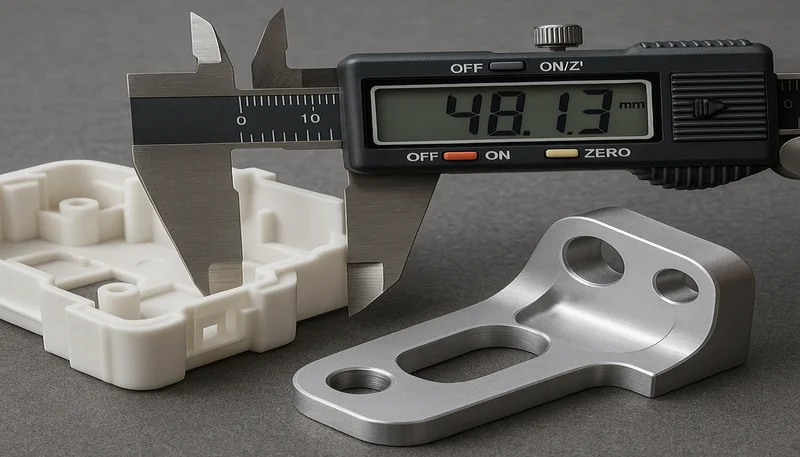
As expectativas de tolerância precisam ser realistas. A moldagem por injeção convencional mantém ±0,1 mm em dimensões inferiores a 25 mm e ±0,3 mm em dimensões superiores a 100 mm. Se você precisar de tolerâncias mais estreitas, haverá custos adicionais não apenas na precisão da fabricação do molde, mas também no controle do processo, na inspeção e, possivelmente, em uma janela de processamento menor. A melhor prática é especificar tolerâncias estreitas somente onde forem funcionalmente necessárias e permitir tolerâncias convencionais nas demais áreas.
Os materiais com fibra de vidro acrescentam outra dificuldade. Contraem menos isotropicamente — mais na direção do fluxo do que na transversal — exigindo gerir contração diferencial. A cavidade deve compensá-la e a janela do processo é mais estreita. Se a peça tiver tolerâncias apertadas e exigir nylon com fibra de vidro, considere-o no projeto desde o início.
Quando as nervuras de apoio superam seções de parede espessas?
As nervuras de suporte são superiores às paredes grossas em praticamente todas as situações — proporcionam rigidez igual com menos material e um tempo de arrefecimento mais rápido. As regras de design são simples: a espessura da nervura deve ser 50–60% da parede nominal, a altura da nervura não deve exceder 3x a parede nominal, e é necessário um mínimo de 0,5° de inclinação por lado em cada nervura.
Muitos projetos falham na interseção de nervuras. Quando duas se cruzam, a espessura local é efetivamente a soma de ambas — suficiente para criar rechupe na superfície oposta. A solução é esvaziar a interseção com uma bossa ou rebaixo, mantendo a espessura local dentro do objetivo de ±10%.
Outro erro comum é posicionar as nervuras longe demais umas das outras. Se o espaçamento exceder 3–4x a espessura da parede, a área sem suporte entre elas poderá flexionar ou empenar durante o arrefecimento. Um espaçamento menor aumenta o custo do material, mas reduz os problemas dimensionais. Para peças estruturais que precisam manter planicidade rigorosa, um padrão de nervuras com espaçamento de 20–30mm é um ponto de partida razoável para uma parede nominal de 2.5mm.
Conclusão: se estiver a analisar o projeto de uma peça em que alguma parede excede 4mm, pare e pergunte se uma parede mais fina com nervuras desempenharia a mesma função. Em quase todos os casos, desempenhará — e o molde funcionará melhor.
Nossa fábrica própria de moldes em Xangai produz mais de 100 conjuntos de moldes de injeção por mês e está equipada com máquinas CNC, máquinas de EDM a fio, gravadoras de precisão e máquinas de corte a fio lento. Cada molde passa por um processo de controle de qualidade em 6 etapas — do IQC ao OQC.
Perguntas frequentes sobre o projeto de moldes de injeção
| Elemento de projeto | Requisito principal | Erro comum |
|---|---|---|
| Espessura da parede | 2–3 mm nominais, com uniformidade de ±10% | Exceder 4mm sem nervuras |
| Ângulo de inclinação | ≥1° por lado (≥2° para texturizado) | Ângulo de saída nulo em paredes verticais |
| Localização do ponto de injeção | Preenchimento equilibrado, linhas de solda seguras | Colocação exclusivamente estética |
| Arrefecimento | Uniforme em todas as cavidades | Perfuração reta apenas em peças complexas |
Perguntas mais frequentes
Qual é o fator mais importante no projeto de moldes de injeção?
A uniformidade da espessura da parede é o fator mais importante no projeto de moldes de injeção. Manter uma variação de até ±10% em toda a peça evita os três defeitos de produção mais comuns encontrados pelos engenheiros: marcas de afundamento em superfícies cosméticas, empenamento que deixa as dimensões fora da especificação e vazios internos que comprometem a integridade estrutural. A espessura da parede determina diretamente a estratégia de posicionamento da comporta, o projeto do layout dos canais de resfriamento e as metas de tempo de ciclo alcançáveis. A análise da espessura da parede é sempre o primeiro parâmetro avaliado durante a revisão do projeto — porque todas as decisões de projeto subsequentes se apoiam nessa base.
De quanto ângulo de saída as peças moldadas por injeção precisam?
O ângulo de saída mínimo na moldagem por injeção é de 1° por lado em todas as superfícies verticais lisas, aplicando-se sem exceção a cada recurso vertical, incluindo nervuras, ressaltos e paredes laterais. Superfícies texturizadas exigem um ângulo significativamente maior — normalmente 2–3° por lado —, e texturas mais profundas ou acabamentos brilhantes podem exigir conicidade ainda maior para garantir a liberação limpa. Um ângulo insuficiente faz as peças aderirem à cavidade durante a extração, resultando em marcas de arraste, riscos superficiais e possíveis danos às caras superfícies do molde. Em dispositivos médicos ou componentes ópticos, nos quais a qualidade superficial é essencial, aumentar o ângulo para 1,5–2° mesmo em superfícies polidas oferece uma margem de segurança importante que evita problemas na produção.
Qual é a tolerância padrão para peças moldadas por injeção?
A moldagem por injeção padrão alcança tolerâncias de ±0,1 mm em dimensões abaixo de 25 mm e ±0,3 mm em dimensões com mais de 100 mm de comprimento. Esses são valores do setor que a maioria das ferramentarias qualificadas mantém consistentemente sem controles extraordinários. Tolerâncias menores — até ±0,05 mm em dimensões pequenas — são possíveis, mas aumentam muito o custo de fabricação e estreitam a janela de processamento, elevando a sensibilidade às variações do lote e dos parâmetros da máquina. A melhor prática é especificar tolerâncias estreitas apenas em dimensões funcionalmente críticas, como alojamentos de rolamentos ou recursos de alinhamento, e permitir tolerâncias padrão nas demais para otimizar o equilíbrio entre custo e qualidade.
Como a localização do ponto de injeção afeta a qualidade da peça moldada por injeção?
A posição do ponto de injeção controla diretamente três aspectos críticos de toda peça moldada: a progressão do padrão de preenchimento do polímero pela cavidade, a posição em que se formam linhas de solda quando frentes de fluxo distintas se encontram e o comprimento máximo de fluxo entre o ponto de injeção e a parede mais distante da cavidade. Um posicionamento inadequado cria bolsas de ar que causam preenchimentos incompletos e marcas de queimadura, posiciona linhas de solda em áreas estruturais de alta tensão e cria pontos fracos, além de produzir pressão de recalque desigual que leva à inconsistência dimensional. A abordagem correta usa software de simulação de fluxo no molde para otimizar a posição durante o projeto, priorizando deliberadamente o preenchimento balanceado da cavidade e uma posição segura para as linhas de solda, em vez de apenas ocultar o ponto por motivos estéticos.
Que espessura de parede é recomendada para peças moldadas por injeção?
Para termoplásticos de engenharia como ABS, PC e nylon, recomenda-se parede nominal de 2–3mm. Acima de 4mm aumenta muito o risco de afundamentos, vazios e ciclos longos sem ganho proporcional de resistência. Em vez de engrossar, use nervuras de suporte com 50–60% da parede. Isto reduz material, encurta o ciclo em 15–25% e melhora a estabilidade.
Como pode o projeto do molde reduzir o tempo de ciclo da moldagem por injeção?
Otimizar a refrigeração é a estratégia de projeto mais eficaz, pois ocupa 50–70% do ciclo. Canais conformados extraem calor mais uniformemente do que furos retos; insertos de cobre-berílio melhoram zonas quentes. Com fluxo equilibrado nas cavidades, estas medidas reduzem ciclos em 20–40% sem perder qualidade ou precisão.
Que aço para moldes é mais adequado para moldes de injeção de alta precisão?
O aço pré-endurecido P20 a 28–32 HRC é a escolha padrão para moldes de produção até 500,000 ciclos, oferecendo um excelente equilíbrio entre maquinabilidade, capacidade de polimento e custo. Para moldes de produção de grande volume destinados a ultrapassar 1 milhão de ciclos, ou moldes que processam materiais abrasivos reforçados com fibra de vidro ou minerais, o aço endurecido H13 a 48–52 HRC proporciona resistência ao desgaste e condutividade térmica significativamente superiores. Para componentes óticos de tolerância apertada ou dispositivos médicos que exigem superfícies com polimento espelhado e resistência à corrosão a longo prazo, o aço inoxidável S136 é a escolha preferida apesar do custo superior. A seleção do aço deve corresponder sempre ao volume total de produção previsto, ao nível de abrasividade do material e à especificação de acabamento superficial exigida.
Melhore o Seu Processo de Design de Moldes de Injeção | ZetarMold
Uma análise abrangente de Projeto para Manufaturabilidade identifica inconsistências de espessura de parede, ângulos de saída insuficientes, complexidade de rebaixos que exige ações laterais e posicionamento inadequado do ponto de injeção antes de qualquer corte no aço. Corrigir esses problemas de projeto durante a etapa de DFM custa aproximadamente dez vezes menos do que modificar um molde de produção concluído por soldagem, nova usinagem ou inserção. Uma análise DFM minuciosa detecta mais de 80% dos possíveis problemas de produção, incluindo muitos que só surgiriam durante a amostragem do primeiro artigo, quando o molde já está construído. A análise DFM deve ser uma etapa obrigatória em todo projeto de molde, independentemente da aparente simplicidade, pois o custo da prevenção é sempre menor que o custo da correção.
Pronto para otimizar seu processo de projeto de moldes de injeção?
A chave para optimizar o processo de design do molde é focar na espessura da parede, colocação da entrada, arrefecimento e seleção de material. Independentemente de estar a começar com um esboço conceptual ou necessitar de uma revisão DFM num design existente, uma equipa de engenharia experiente pode ajudar a fazer tudo correctamente desde o início.
Precisa de uma análise de DFM ou de um orçamento para o projeto do molde? Nossos gerentes de projeto que falam inglês respondem em até 24 horas com comentários detalhados, recomendações de processo e preços competitivos.
Solicite uma cotação gratuita →
DFM: DFM refere-se à prática de otimizar a geometria da peça e do molde durante a fase de projeto para reduzir defeitos de produção, diminuir o custo do ferramental e encurtar o prazo de entrega. ↩
espessura da parede: A espessura da parede é a distância entre as superfícies externa e interna de uma peça moldada; uma espessura uniforme evita marcas de afundamento, empenamento e vazios. ↩
ângulo de saída: O ângulo de saída é uma pequena inclinação aplicada às superfícies verticais de uma peça moldada para permitir sua ejeção limpa da cavidade do molde, sem riscos nem deformação. ↩