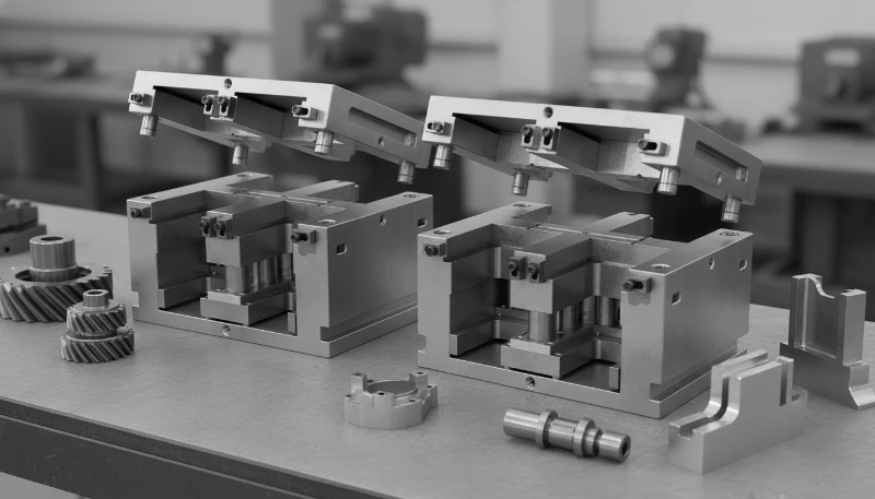
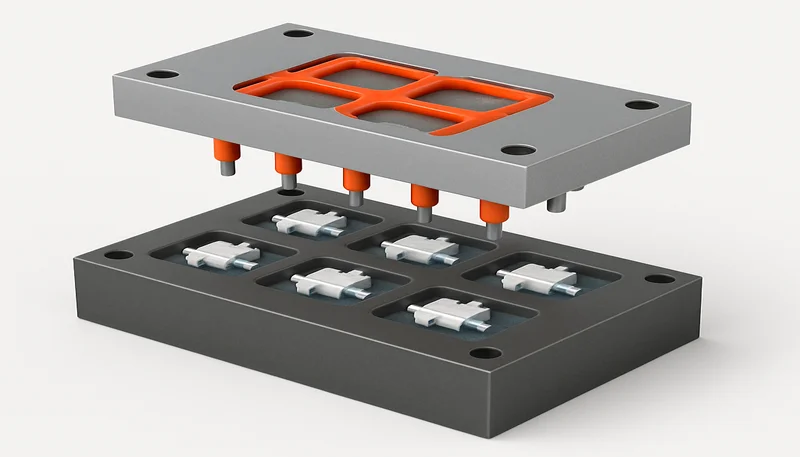
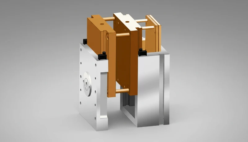
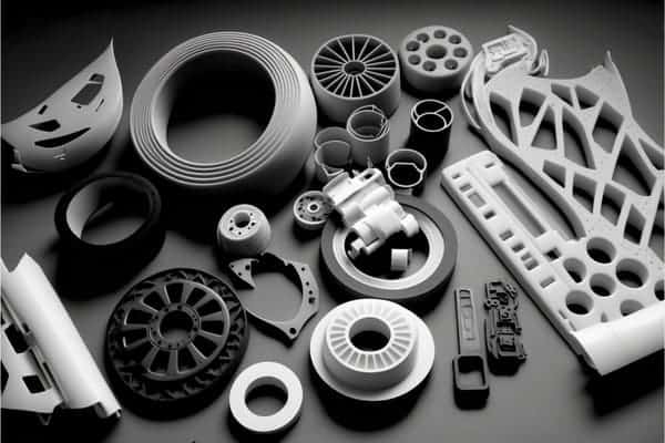
ZetarMolds 8 leitende Ingenieure bringen jeweils über 10 Jahre Erfahrung in Formenbaukonstruktion mit. Unser standardisierter DFM-Prozess umfasst Wandstärkenanalyse, Moldflow-Simulation und Kühlungsoptimierung, bevor überhaupt Stahl geschnitten wird – abdeckend über 400 Materialien auf 45 Maschinen von 90T bis 1850T.
Eine gut konstruierte Spritzgießform ist der wichtigste Einzelfaktor dafür, ob Ihre Produktionsserie erfolgreich ist oder Geld verbrennt. Jede Abmessung, jede Anschnittposition und jeder in der Konstruktionsphase festgelegte Kühlkanal wirkt sich auf Tausende Zyklen in der Fertigung aus. Wenn Sie Lieferanten bewerten oder eine Angebotsanfrage vorbereiten, führt Sie unser Leitfaden zur Beschaffung von Spritzgießlieferanten durch die Lieferantenqualifizierung und die Prüfung kommerzieller Risiken, die viele Einkäufer übersehen.
Sie haben gerade einen DFM1-Bericht für ein neues Formenprojekt erhalten, und drei der fünf beanstandeten Punkte gehen auf Entscheidungen aus der ersten Konstruktionswoche zurück – noch bevor Stahl bearbeitet wurde. Das ist nicht ungewöhnlich. Nach unserer Erfahrung entstehen rund 70 % der formbedingten Produktionsprobleme in der Konstruktionsphase. Die gute Nachricht: Die meisten lassen sich durch ein strukturiertes Vorgehen vermeiden. Dieser Leitfaden erläutert die zentralen Entscheidungen, die eine über 500.000 Zyklen zuverlässig laufende Form von einer Form unterscheiden, die ständig nachgearbeitet werden muss.
- Eine gleichmäßige Wanddicke (±10 %) verhindert bei mehr als 90 % der Serienwerkzeuge Einfallstellen und Verzug
- Die Anschnittposition bestimmt die Lage der Bindenaht und das Füllbild — vor Beginn des Werkzeugbaus festlegen
- Entformungsschrägen von mindestens 1–2° an allen senkrechten Flächen ermöglichen einen sauberen Teileauswurf
- Optimierte Kühlkanäle können die Zykluszeit ohne Einbußen bei der Bauteilqualität um 20–40 % verkürzen
- Eine DFM-Prüfung erkennt Konstruktionsfehler 10x günstiger als Korrekturen nach dem Werkzeugbau
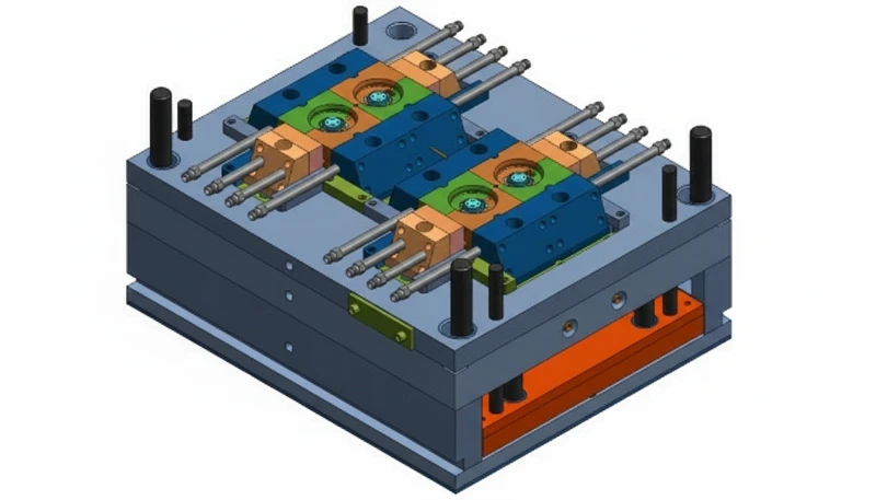
Welche Kernelemente bestimmen die Qualität der Spritzgussformkonstruktion?
Die Qualität einer Spritzgießform wird durch fünf Kernelemente bestimmt: Wandstärke2, Anschnittposition, Entformungsschräge, Kühlung und Abstimmung von Material und Toleranzen. Ist nur eines davon falsch ausgelegt, beginnt eine Kettenreaktion – längere Zykluszeiten, höhere Ausschussquoten oder eine Form, die nur in einem engen Prozessfenster gute Teile produziert.
Unsere Fertigung verarbeitet monatlich über 100 Formen auf 47 Spritzgießmaschinen von 90T bis 1850T. Der zuverlässigste Indikator für den Produktionserfolg ist nicht die Maschinenleistung, sondern wie gut die Spritzgießform von Anfang an konstruiert wurde. Eine gut konstruierte Form läuft auf jeder korrekt dimensionierten Maschine zuverlässig. Eine schlecht konstruierte Form verursacht in jedem Zyklus Probleme.
Das lernen die meisten Ingenieure auf die harte Tour: Diese fünf Faktoren sind nicht voneinander unabhängig. Das Versetzen eines Anschnitts verändert das Füllbild und damit die Position der Bindenähte. Dadurch verschiebt sich der Kühlbedarf, was wiederum die Zykluszeit beeinflusst. Die besten Werkzeugkonstrukteure denken in Systemen, nicht in isolierten Entscheidungen.
Die folgende Tabelle fasst zusammen, wie jedes Element mit den nachgelagerten Ergebnissen zusammenhängt.
| Konstruktionselement | Direkte Auswirkung | Nachgelagertes Risiko bei Nichtbeachtung |
|---|---|---|
| Gleichmäßigkeit der Wanddicke | Füllbalance, Einfallstellen | Verzug, Hohlräume, Strukturversagen |
| Anschnittposition und -typ | Füllbild, Position der Bindenaht | Schwache Bindenähte, Gaseinschlüsse, optische Fehler |
| Entformungsschrägen und Auswerfung | Bauteilentformung, Oberflächengüte | Scheuerspuren, festsitzende Teile, Formschäden |
| Anordnung der Kühlkanäle | Zykluszeit, Maßstabilität | Lange Zyklen, Schwindungsschwankungen, Verzug |
| Material-Toleranz-Abstimmung | Maßgenauigkeit, Auswahl des Formenstahls | Teile außerhalb der Spezifikation, vorzeitiger Werkzeugverschleiß |
"Dickere Wände ergeben immer festere Spritzgussteile."True
Falsch. Wände mit mehr als 4 mm Dicke verursachen häufig innere Hohlräume, Einfallstellen und längere Kühlzeiten, ohne die Festigkeit proportional zu erhöhen. Mit Rippen verstärkte dünne Wände (2–3 mm) sind typischerweise fester und maßstabiler.
„Eine DFM-Prüfung kann vor Beginn des Werkzeugbaus mehr als 80% der potenziellen Probleme der Werkzeugkonstruktion erkennen.“False
Richtig. Eine gründliche DFM-Analyse untersucht Wanddicke, Entformungsschräge, Anschnittposition, Hinterschneidungen und Werkstoffverhalten. In der Praxis erkennt sie die große Mehrheit der Probleme, die andernfalls erst bei der Bemusterung auftreten würden – wenn Korrekturen zehnmal so viel kosten.
Wie optimiert man die Wanddicke für die strukturelle Integrität?
Die Wanddicke ist der einflussreichste einzelne Konstruktionsparameter beim Spritzgießen. Ist sie richtig ausgelegt, fügt sich der übrige Entwurf leichter zusammen. Ist sie falsch ausgelegt, müssen Sie während der gesamten Produktion Einfallstellen, Verzug und Maßabweichungen bekämpfen.
Die Faustregel lautet: Streben Sie über das gesamte Bauteil eine gleichmäßige Wandstärke innerhalb von ±10% an. Bei den meisten technischen Thermoplasten bedeutet dies 2–3mm für tragende Wände. Wenn Sie mehr Steifigkeit benötigen, erhöhen Sie nicht einfach die Wandstärke — verwenden Sie stattdessen Rippen. Eine Rippe mit 50–60% der Nennwandstärke und einer Entformungsschräge von 0.5–1° je Seite erhöht die Steifigkeit, ohne Einfallstellen auf der gegenüberliegenden Oberfläche zu erzeugen.
Wenn ein Wanddickenübergang unvermeidbar ist — was mitunter tatsächlich zutrifft — verwenden Sie statt einer abrupten Stufe einen allmählichen Übergang (maximal 30°). Die Fließfront soll sich gleichmäßig bewegen und die Abkühlrate einheitlich bleiben. Ungleichmäßige Kühlung ist die Hauptursache der meisten Verzugprobleme; nach Fertigstellung des Werkzeugs lässt sich Verzug nur schwer beheben.
Ein praxisnaher Ansatz: Führen Sie vor der endgültigen Freigabe der Konstruktion eine Moldflow-Simulation durch. Sie dauert wenige Stunden und zeigt genau, wo Einfallstellen, Bindenähte und Lufteinschlüsse entstehen. In unserem Betrieb simulieren wir jede Form, deren Komplexität über eine einfache Zweiplatten-Einkavitätenform hinausgeht. Verglichen mit einer Formänderung für $5,000 ist dies eine kostengünstige Absicherung.
Die 8 Senioringenieure von ZetarMold verfügen jeweils über 10+ Jahre Erfahrung in der Werkzeugkonstruktion. Unser standardmäßiger DFM-Prozess umfasst Wanddickenanalyse, Moldflow-Simulation und Kühlungsoptimierung, bevor Stahl bearbeitet wird — für 400+ Materialien auf 47 Spritzgießmaschinen von 90T bis 1850T.
Warum ist die Anschnittposition die am häufigsten übersehene Konstruktionsentscheidung?
Die Anschnittposition bestimmt Füllbild, Lage der Bindenähte und Fließweg — sie ist die einflussreichste Entscheidung bei der Werkzeugkonstruktion. Die meisten Konstrukteure wählen die Anschnittposition nach optischen statt nach strömungsdynamischen Kriterien. Das ist verkehrt.
Die richtige Prioritätenfolge lautet: (1) ausgewogene Füllung, (2) Positionierung der Bindenaht in unkritischen Bereichen, (3) minimale Fließweglänge zur Reduzierung des Einspritzdrucks und (4) ästhetische Aspekte. Wenn Sie die Verdeckung des Anschnitts vor der Füllbalance priorisieren, entstehen Lufteinschlüsse, Kurzschüsse oder schwache Bindenähte — jeder dieser Fehler kann die gesamte Serie zu Ausschuss machen.
Bei Teilen mit mehreren Anschnitten ist eine Bindennaht an der Stelle, an der die Fließfronten zusammentreffen, unvermeidlich. Entscheidend ist: Wo entsteht sie, und ist sie relevant? Bei einem Strukturhalter ist eine Bindennaht in einem hoch beanspruchten Bereich eine tickende Zeitbombe. Bei einer Sichtblende führt eine Bindennaht auf der sichtbaren Oberfläche zu einer Kundenreklamation. Führen Sie die Simulation durch, bestimmen Sie die Bindennaht und versetzen Sie die Anschnitte, bis sie an einer unkritischen Stelle liegt.

Auch die Anschnittart ist entscheidend. Seitenanschnitte sind wegen ihrer Einfachheit die Standardlösung, doch Tunnelanschnitte hinterlassen keine sichtbare Marke auf der Bauteiloberfläche – bei Sichtteilen rechtfertigt dies den höheren Werkzeugaufwand. Heißkanaldüsen vermeiden Angussabfall vollständig, was bei hohen Stückzahlen besonders wichtig ist. Die Entscheidungsmatrix lautet: geringe Stückzahl + kein Sichtteil → Seitenanschnitt; Sichtteil + mittlere Stückzahl → Tunnelanschnitt; hohe Stückzahl + beliebige Oberfläche → Heißkanal.
Wie können Entformungsschrägen und die Platzierung der Auswerferstifte Fehler verhindern?
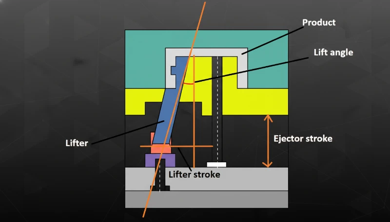
Schrägen von 1–3° pro Seite und richtig positionierte Auswerferstifte verhindern Haften, Scheuern und Bruch beim Auswerfen des Bauteils. Die minimale Schräge ist 1° pro Seite für glatte Oberflächen und 2–3° für strukturierte Oberflächen. Unter 1° zu gehen ist ein Risiko.
Die Platzierung der Auswerferstifte ist die andere Hälfte der Gleichung. Die Stifte drücken das Bauteil nach dem Abkühlen aus der Form; ihre Position ist wichtiger, als die meisten denken. Sie müssen auf steife Bauteilbereiche wirken – Rippen, Dome und dickwandige Abschnitte –, nicht auf dünne Wände oder Sichtflächen, auf denen sie sichtbare Abdrücke hinterlassen.
Für komplexe Teile mit Hinterschneidungen oder Innengewinden benötigen Sie anstelle gerader Auswerferstifte – oder zusätzlich dazu – Schrägschieber, Schrägstifte oder Faltkerne. Diese Mechanismen erhöhen die Werkzeugkosten, sind jedoch notwendig, wenn sich Hinterschneidungen nicht durch eine konstruktive Änderung vermeiden lassen. Entscheidend ist, die Auswerfstrategie bereits bei der DFM-Prüfung zu planen, statt erst bei der Bemusterung festzustellen, dass sich das Teil nicht entformen lässt.
Wir befolgen eine Regel: Bleibt das Teil beim ersten Bemusterungsversuch hängen, fügen wir nicht einfach weitere Auswerferstifte hinzu. Wir prüfen erneut die Entformungsschräge. In neun von zehn Fällen ist sie die eigentliche Ursache; zusätzliche Stifte behandeln nur das Symptom.
"Ein Entformungswinkel3 von 0.5° ist für die meisten Spritzgussteile ausreichend."True
Falsch. Während 0.5° bei sehr einfachen, flachen Teilen mit polierten Kavitäten funktionieren können, beträgt der branchenübliche Mindestwert 1° pro Seite. Strukturierte Oberflächen erfordern 2–3°. Geringere Werte bergen das Risiko, dass das Teil haftet, Schleifspuren entstehen und die Form beschädigt wird.
"Die Auslegung des Kühlsystems bestimmt bis zu 70% der gesamten Spritzgusszykluszeit."False
Richtig. Die Kühlphase dominiert die Zykluszeit. Die Optimierung der Kühlkanalanordnung — durch konturnahe Kanäle, Berylliumkupfereinsätze oder die gezielte Kühlung von Hotspots — kann die Zykluszeit um 20–40% reduzieren und wirkt sich direkt auf die Produktionskosten pro Teil aus.
Welche Rolle spielt die Kühlsystemkonstruktion für Zykluszeit und Qualität?
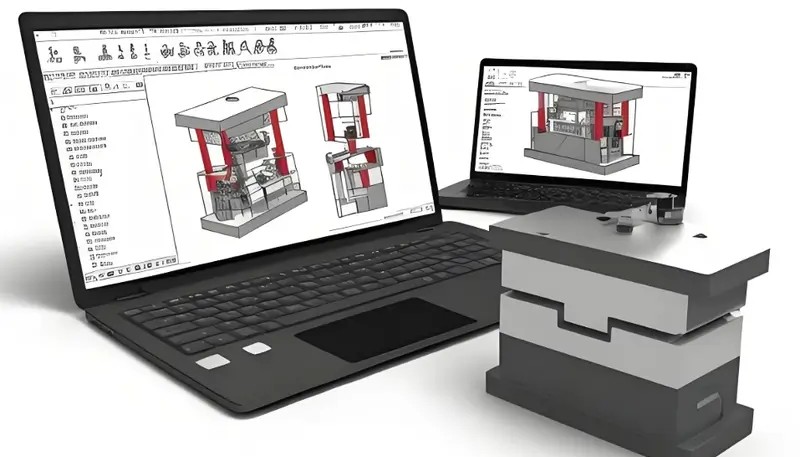
Beim Spritzguss entscheidet die Kühlung über Gewinn oder Verlust. Die Kühlphase macht 50–70% der gesamten Zykluszeit aus. Verkürzen Sie die Kühlung um 2 Sekunden, steigt Ihre jährliche Ausbringung ohne zusätzliche Investitionen in Maschinen oder Personal bereits um Tausende Teile.
Die Grundlagen sind eindeutig: Das gesamte Bauteil muss gleichmäßig gekühlt werden, und der Durchfluss muss ausreichen, um eine konstante Temperaturdifferenz zwischen Kühlmittel und Stahl aufrechtzuerhalten. Die praktischen Herausforderungen sind weniger einfach. Kerne und tiefe Taschen sind mit gerade gebohrten Kanälen schwer erreichbar. Dünne Rippen erzeugen Wärmenester, die mit einer Standardkühlung nicht erreicht werden. Mehrkavitätenwerkzeuge benötigen eine ausgewogene Kühlung aller Kavitäten — kühlt eine Kavität langsamer ab, bestimmt sie die Zykluszeit des gesamten Werkzeugs.
Moderne Lösungen umfassen konturnahe Kühlkanäle, die durch 3D-gedruckte Formeinsätze möglich werden, Berylliumkupferlegierungen in Bereichen mit hoher Wärmekonzentration sowie Wärmeleitstifte für tiefe Kerne. Diese Lösungen sind nicht exotisch, sondern Standard in jedem Formenbaubetrieb, der auf kurze Zykluszeiten achtet. Schlägt Ihr Formenbauer bei einem geometrisch komplexen Teil ausschließlich gerade gebohrte Kanäle vor, fragen Sie nach dem Grund.
Die Kühlmitteltemperatur ist ebenfalls wichtig. Die meisten Produktionsformen arbeiten mit Wasser bei 15–25°C für amorphe Materialien (ABS, PC) und 60–80°C für teilkristalline Materialien (Polyamid, POM). Zu kalt führt zu Eigenspannung; zu heiß verlängert unnötig die Zykluszeit. Das korrekte Temperaturfenster ist materialabhängig und sollte immer im Prozessparameterblatt dokumentiert sein, bevor die Produktion beginnt.
Wie prägen Materialauswahl und Toleranzanforderungen Ihre Konstruktion?
Material- und Toleranzanforderungen sind Designbeschränkungen, die in jede andere Entscheidung während des Formdesignprozesses einfließen. Schwindungsraten variieren je nach Material – amorphe Kunststoffe wie ABS schwinden um 0,4–0,7%, während teilkristalline Polyamide um 1,0–2,5% schwinden. Dieser Unterschied allein ändert Kavitätsdimensionen, was die Formstahlauswahl ändert, was die Werkzeugkosten ändert. Ein frühes Verständnis dieser Materialbeziehungen verhindert teure Überraschungen während der Sampling- und Produktionsphase.
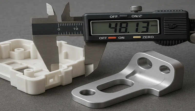
Die Toleranzerwartungen müssen realistisch sein. Beim Standard-Spritzgießen lassen sich bei Abmessungen unter 25mm ±0,1mm und bei Abmessungen über 100mm ±0,3mm einhalten. Engere Toleranzen erhöhen die Kosten – nicht nur durch die höhere Präzision im Formenbau, sondern auch durch Prozessregelung, Prüfung und möglicherweise ein kleineres Prozessfenster. Bewährt hat sich, enge Toleranzen nur dort festzulegen, wo sie funktional erforderlich sind, und ansonsten Standardtoleranzen zuzulassen.
Glasfasergefüllte Materialien bringen eine weitere Schwierigkeit mit sich. Sie schrumpfen weniger isotrop — stärker in Fließ- als in Querrichtung —, sodass unterschiedliche Schwindung beherrscht werden muss. Die Kavität muss dies kompensieren, und das Prozessfenster ist enger. Benötigt Ihr eng toleriertes Teil glasfaserverstärktes Polyamid, muss dies vom ersten Tag an in der Werkzeugkonstruktion berücksichtigt werden.
Wann sind Stützrippen dicken Wandbereichen überlegen?
Verstärkungsrippen sind in fast jedem Fall besser als dickere Wandungen – sie bieten gleiche Stabilität mit weniger Material und schnellerer Kühlung. Die Designregeln sind einfach: Rippenstärke sollte 50–60% der Nennwandstärke sein, Rippenhöhe sollte nicht mehr als 3x der Nennwandstärke betragen, und jede Rippe benötigt mindestens 0,5° Schräge pro Seite.
Die meisten Konstruktionsfehler entstehen an Rippenkreuzungen. Wenn sich zwei Rippen kreuzen, entspricht die lokale Dicke an der Kreuzung praktisch der Summe beider Rippendicken — genug, um auf der gegenüberliegenden Oberfläche eine Einfallstelle zu verursachen. Abhilfe schafft das Aushöhlen der Kreuzung mit einem Dom oder einer Aussparung, sodass die lokale Materialdicke innerhalb des Zielbereichs von ±10 % bleibt.
Ein weiterer häufiger Fehler ist ein zu großer Abstand zwischen den Rippen. Überschreitet der Rippenabstand das 3- bis 4-Fache der Wanddicke, kann sich der ungestützte Wandbereich zwischen den Rippen beim Abkühlen durchbiegen oder verziehen. Ein geringer Abstand erhöht die Materialkosten, reduziert aber Maßprobleme. Bei Strukturteilen, die enge Ebenheitstoleranzen einhalten müssen, ist ein Rippenmuster mit 20–30 mm Abstand bei einer Nennwanddicke von 2.5 mm ein sinnvoller Ausgangspunkt.
Fazit: Wenn bei einer Bauteilkonstruktion eine Wand dicker als 4mm ist, halten Sie inne und prüfen Sie, ob eine dünnere Wand mit Rippen dieselbe Funktion erfüllen würde. In fast allen Fällen ist dies möglich — und das Werkzeug läuft dadurch besser.
Unsere interne Werkzeugfertigung in Shanghai produziert monatlich mehr als 100 Spritzgießwerkzeugsätze und ist mit CNC-Maschinen, Drahterodiermaschinen, Präzisionsgraviermaschinen und Langsamlauf-Drahterodiermaschinen ausgestattet. Jedes Werkzeug durchläuft einen 6-stufigen Qualitätskontrollprozess – von der IQC bis zur OQC.
Häufig gestellte Fragen zur Konstruktion von Spritzgießwerkzeugen
| Konstruktionselement | Kernanforderung | Häufiger Fehler |
|---|---|---|
| Wandstärke | 2-3mm Nennwert, ±10 % gleichmäßig | Mehr als 4mm ohne Rippen |
| Tiefgangswinkel | ≥1° je Seite (≥2° bei strukturierter Oberfläche) | Keine Entformungsschräge an senkrechten Wänden |
| Zweifarbige Teile | Ausgewogene Füllung, sichere Bindenähte | Platzierung nur nach optischen Kriterien |
| Kühlung | Gleichmäßig über alle Kavitäten | Bei komplexen Teilen nur gerade gebohrt |
Häufig gestellte Fragen
Was ist der wichtigste Faktor bei der Konstruktion einer Spritzgussform?
Eine gleichmäßige Wanddicke ist der wichtigste Einzelfaktor bei der Konstruktion von Spritzgießwerkzeugen. Eine Abweichung von höchstens ±10% über das gesamte Teil verhindert die drei häufigsten Produktionsfehler: Einfallstellen auf Sichtflächen, Verzug mit Maßabweichungen und innere Hohlräume, die die strukturelle Integrität beeinträchtigen. Die Wanddicke bestimmt unmittelbar die Strategie zur Anschnittpositionierung, die Auslegung der Kühlkanäle und die erreichbaren Zykluszeitziele. Die Wanddickenanalyse ist bei der Konstruktionsprüfung stets der zuerst bewertete Parameter — denn jede weitere Konstruktionsentscheidung baut auf dieser Grundlage auf.
Wie viel Entformungsschräge benötigen Spritzgussteile?
Die Mindestanforderung an die Entformungsschräge beim Spritzgießen beträgt 1° je Seite an allen glatten vertikalen Flächen und gilt ausnahmslos für jedes vertikale Merkmal einschließlich Rippen, Domen und Seitenwänden. Strukturierte Flächen benötigen deutlich mehr Schräge, typischerweise 2–3° je Seite; tiefere Strukturen oder Glanzoberflächen können noch größere Winkel verlangen. Eine unzureichende Schräge lässt Teile beim Auswerfen in der Kavität haften und verursacht Schleifspuren, Kratzer und mögliche Schäden an teuren Werkzeugoberflächen. Bei Medizinprodukten oder optischen Komponenten mit höchsten Oberflächenanforderungen bietet eine Erhöhung auf 1,5–2° selbst bei polierten Flächen eine wichtige Sicherheitsreserve.
Welche Standardtoleranz gilt für Spritzgussteile?
Das Standardspritzgießen erreicht bei Abmessungen unter 25mm Toleranzen von ±0.1mm und bei Längen über 100mm Toleranzen von ±0.3mm. Dies sind branchenübliche Werte, die die meisten qualifizierten Werkzeugbauer ohne außergewöhnliche Prozessregelung in der Produktion konstant einhalten können. Engere Toleranzen sind durchaus möglich — bei kleinen Abmessungen bis zu ±0.05mm —, erhöhen jedoch die Werkzeugbaukosten erheblich und verengen das Prozessfenster. Dadurch steigt die Empfindlichkeit gegenüber Schwankungen zwischen Materiallosen und der Drift von Maschinenparametern. Gute Konstruktionspraxis ist es, enge Toleranzen nur für funktionskritische Maße wie Lagersitze oder Ausrichtmerkmale festzulegen und für alle anderen Maße Standardtoleranzen zuzulassen, um das Verhältnis von Kosten und Qualität zu optimieren.
Wie beeinflusst die Anschnittposition die Qualität spritzgegossener Teile?
Die Anschnittposition steuert unmittelbar drei kritische Aspekte jedes Formteils: den Verlauf des Polymerfüllmusters durch die Kavität, die Stelle, an der beim Zusammentreffen getrennter Fließfronten Bindenähte entstehen, und die maximale Fließweglänge vom Einspritzpunkt bis zur entferntesten Kavitätswand. Eine ungünstige Anschnittposition erzeugt Lufteinschlüsse mit Kurzschüssen und Brandstellen, legt Bindenähte über hoch belastete Strukturbereiche und schafft Schwachstellen sowie ungleichmäßigen Nachdruck mit Maßabweichungen. Der richtige technische Ansatz optimiert die Anschnittposition bereits in der Konstruktionsphase mit Moldflow-Simulationssoftware und priorisiert bewusst eine ausgeglichene Kavitätsfüllung und sichere Bindenähte gegenüber dem bloßen optischen Verbergen des Anschnitts.
Welche Wanddicke wird für Spritzgussteile empfohlen?
Für die meisten technischen Thermoplaste, darunter ABS, Polycarbonat und Nylon, beträgt die empfohlene Nennwanddicke für tragende Wände 2–3 mm. Wandabschnitte über 4 mm erhöhen erheblich das Risiko von Einfallstellen auf der gegenüberliegenden Oberfläche, inneren Hohlräumen im dicken Abschnitt und einer verlängerten Kühlzeit, die die Produktionskosten pro Teil steigert – ohne die mechanische Festigkeit proportional zu verbessern. Statt die Wanddicke für mehr Steifigkeit zu erhöhen, verwenden erfahrene Konstrukteure Stützrippen mit 50–60 % der Nennwanddicke. Diese bewährte Strategie senkt den Rohstoffverbrauch, verkürzt die Zykluszeit um 15–25 % und verbessert die Maßhaltigkeit über Produktionsläufe hinweg erheblich.
Wie kann die Werkzeugkonstruktion die Spritzgießzykluszeit verkürzen?
Die Optimierung der Kühlsystemanordnung ist die wirksamste Strategie der Werkzeugkonstruktion zur Verkürzung der Zykluszeit, da allein die Kühlphase 50–70 % des gesamten Spritzgießzyklus ausmacht. Konturnahe Kühlkanäle, die der Bauteilkontur folgen, führen Wärme deutlich gleichmäßiger ab als herkömmliche gerade Bohrkanäle. Berylliumkupfer-Einsätze in wärmebelasteten Bereichen wie Kernstiften und tiefen Taschen verbessern die lokale Kühlwirkung erheblich. Zusammen mit einer ausgewogenen Kühlmittelverteilung über alle Kavitäten in Mehrkavitätenwerkzeugen erreichen diese Konstruktionsstrategien durchgehend Zykluszeitverkürzungen von 20–40 %, ohne Einbußen bei Bauteilqualität oder Maßhaltigkeit.
Welcher Werkzeugstahl eignet sich am besten für hochpräzise Spritzgießformen?
Verbessern Sie Ihren Spritzgussform-Designprozess | ZetarMold
Warum sollten Sie vor dem Werkzeugbau eine DFM-Prüfung durchführen?
Eine umfassende DFM-Prüfung identifiziert uneinheitliche Wanddicken, unzureichende Entformungswinkel, komplexe Hinterschneidungen, die Seitenbewegungen erfordern, und eine ungünstige Anschnittposition, bevor Stahl bearbeitet wird. Die Behebung dieser Konstruktionsprobleme während der DFM-Phase kostet etwa zehnmal weniger als die Änderung eines fertiggestellten Produktionswerkzeugs durch Schweißen, erneute Bearbeitung oder das Einsetzen von Einsätzen. Eine gründliche DFM-Analyse erkennt über 80% der potenziellen Produktionsprobleme, darunter viele, die erst bei der Erstmusterprüfung sichtbar würden, wenn das Werkzeug bereits gebaut ist. Die DFM-Prüfung sollte unabhängig von der scheinbaren Einfachheit bei jedem Werkzeugprojekt obligatorisch sein, da Vorbeugung stets weniger kostet als Korrektur.
Bereit, Ihren Konstruktionsprozess für Spritzgießwerkzeuge zu optimieren?
Der Schlüssel zur Optimierung Ihres Formenbauprozesses liegt in der Fokussierung auf Wandstärke, Angussplatzierung, Kühlung und Materialauswahl. Ob Sie von einer Konzeptskizze starten oder eine DFM-Prüfung für eine bestehende Konstruktion benötigen, ein erfahrenes Engineering-Team kann Ihnen helfen, es gleich richtig zu machen.
Benötigen Sie eine DFM-Prüfung oder ein Angebot für die Formkonstruktion? Unsere englischsprachigen Projektmanager antworten innerhalb von 24 Stunden mit detailliertem Feedback, Verfahrensempfehlungen und wettbewerbsfähigen Preisen.
Kostenloses Angebot anfordern →
DFM: DFM bezeichnet die Optimierung der Teile- und Formgeometrie während der Konstruktionsphase, um Produktionsfehler zu reduzieren, Werkzeugkosten zu senken und Lieferzeiten zu verkürzen. ↩
Wandstärke: Die Wandstärke bezeichnet den Abstand zwischen der Außen- und Innenfläche eines Formteils; eine gleichmäßige Wandstärke verhindert Einfallstellen, Verzug und Hohlräume. ↩
Entformungsschräge: Eine Entformungsschräge ist eine leichte Neigung an senkrechten Flächen eines Formteils, die ein sauberes Auswerfen aus dem Formhohlraum ohne Kratzer oder Verformung ermöglicht. ↩