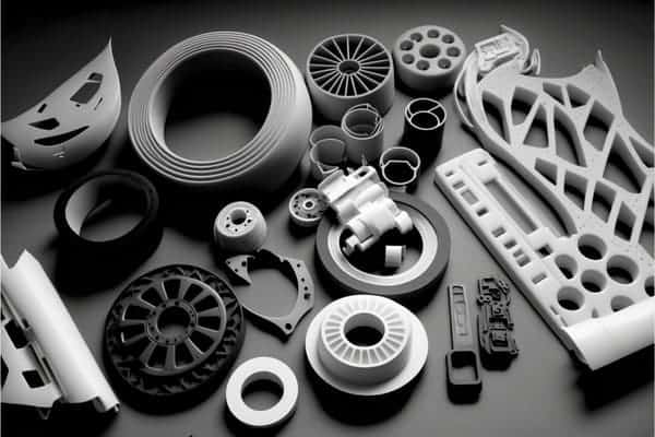
Perché la progettazione dello stampo a iniezione determina il successo della produzione?
Uno stampo a iniezione ben progettato è il fattore più importante per stabilire se una produzione avrà successo o comporterà perdite. Ogni dimensione, posizione del punto di iniezione e canale di raffreddamento deciso in fase di progettazione si ripercuote su migliaia di cicli in reparto. Se stai valutando fornitori o preparando una RFQ, la nostra guida alla selezione dei fornitori di stampaggio a iniezione illustra la qualifica dei fornitori e i controlli sui rischi commerciali che la maggior parte degli acquirenti trascura.
Hai appena ricevuto un rapporto DFM1 per un nuovo progetto di stampo e tre dei cinque problemi segnalati derivano da decisioni prese nella prima settimana di progettazione, prima ancora di lavorare l’acciaio. Non è insolito. Secondo la nostra esperienza, circa il 70% dei problemi di produzione legati agli stampi nasce in fase di progettazione. La buona notizia? La maggior parte si può prevenire seguendo un approccio strutturato. Questa guida esamina le decisioni fondamentali che distinguono uno stampo capace di funzionare senza problemi per oltre 500K cicli da uno che richiede continue rilavorazioni.
- Uno spessore uniforme delle pareti (±10%) previene risucchi e deformazioni in oltre il 90% degli stampi di produzione
- La posizione del punto di iniezione determina quella della linea di saldatura e lo schema di riempimento: decidetela prima di avviare la costruzione dello stampo
- Angoli di sformo minimi di 1–2° su tutte le superfici verticali consentono un’espulsione pulita
- Circuiti di raffreddamento ottimizzati possono ridurre il tempo ciclo del 20–40% senza compromettere la qualità del componente
- La revisione DFM individua i difetti di progettazione a un costo 10x inferiore rispetto alle correzioni dopo la costruzione dello stampo
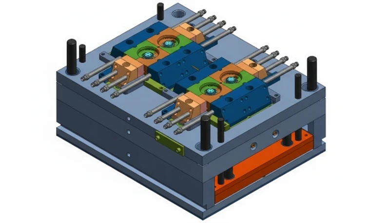
Quali sono gli elementi fondamentali che determinano la qualità della progettazione di uno stampo a iniezione?
La qualità della progettazione di uno stampo a iniezione dipende da cinque elementi fondamentali: spessore delle pareti2, posizione del punto di iniezione, angolo di sformo, raffreddamento e compatibilità tra materiale e tolleranze. Basta sbagliarne uno perché inizi un effetto domino: cicli più lunghi, più scarti oppure uno stampo che produce componenti conformi solo entro una finestra di processo ristretta.
Il nostro reparto produttivo gestisce oltre 100 stampi al mese su 47 presse a iniezione da 90T a 1850T. L’indicatore più affidabile del successo produttivo non è la capacità della macchina, ma la qualità con cui lo stampo a iniezione è stato progettato fin dall’inizio. Uno stampo ben progettato funziona in modo affidabile su qualsiasi macchina correttamente dimensionata. Uno stampo mal progettato crea problemi a ogni ciclo.
Ecco ciò che la maggior parte degli ingegneri impara a proprie spese: questi cinque fattori non sono indipendenti. Spostare un punto di iniezione modifica il profilo di riempimento, che influisce sul punto in cui si formano le linee di saldatura, modifica le zone su cui concentrare il raffreddamento e incide sul tempo di ciclo. I migliori progettisti di stampi ragionano per sistemi, non per decisioni isolate.
La tabella seguente riassume il collegamento tra ciascun elemento e i risultati a valle.
| Elemento di progettazione | Impatto diretto | Rischio a valle se ignorato |
|---|---|---|
| Uniformità dello spessore di parete | Bilanciamento del riempimento, segni di risucchio | Deformazioni, vuoti, cedimenti strutturali |
| Posizione e tipo del punto di iniezione | Schema di riempimento, posizione della linea di saldatura | Linee di giunzione deboli, sacche di gas, difetti estetici |
| Angoli di sformo ed espulsione | Distacco del pezzo, finitura superficiale | Segni di sfregamento, componenti bloccati, danni allo stampo |
| Disposizione dei canali di raffreddamento | Tempo ciclo, stabilità dimensionale | Cicli lunghi, variazione del ritiro, deformazione |
| Compatibilità tra materiale e tolleranza | Precisione dimensionale, scelta dell'acciaio dello stampo | Pezzi fuori specifica, usura prematura dello stampo |
"Pareti più spesse producono sempre componenti stampati a iniezione più resistenti."True
Falso. Pareti più spesse di 4mm generano spesso vuoti interni, risucchi e tempi di raffreddamento più lunghi senza aumenti proporzionali della resistenza. Pareti sottili rinforzate con nervature (2–3mm) sono generalmente più resistenti e dimensionalmente stabili.
"Una revisione DFM può individuare oltre l'80% dei potenziali problemi di progettazione dello stampo prima dell'avvio della costruzione."False
Vero. Un'analisi DFM completa esamina spessori, sformi, punti di iniezione, sottosquadri e comportamento del materiale. In pratica rileva quasi tutti i problemi che altrimenti emergerebbero al campionamento, quando correggerli costa 10 volte di più.
Come si ottimizza lo spessore delle pareti per garantire l’integrità strutturale?
Lo spessore di parete è il singolo parametro progettuale più influente nello stampaggio a iniezione. Se è corretto, il resto del progetto si definisce più facilmente. Se è errato, per l’intera produzione occorrerà contrastare risucchi, deformazioni e deriva dimensionale.
Regola pratica: mantenere uno spessore di parete uniforme entro ±10% sull’intero pezzo. Per la maggior parte dei termoplastici tecnici, ciò significa 2–3mm per le pareti strutturali. Se serve maggiore rigidità, non aumentare semplicemente lo spessore della parete: aggiungere invece nervature. Una nervatura pari al 50–60% dello spessore nominale della parete, con uno sformo di 0.5–1° per lato, aumenta la rigidità senza creare risucchi sulla superficie opposta.
Quando non è possibile evitare una variazione di spessore — e a volte non lo è davvero — usare una rastremazione graduale (massimo 30°) invece di un gradino netto. L’obiettivo è mantenere uniforme l’avanzamento del fronte di flusso e la velocità di raffreddamento. Il raffreddamento disuniforme è la causa principale della maggior parte delle deformazioni, uno dei difetti più difficili da correggere dopo l’attrezzaggio.
Un approccio pratico consiste nell’eseguire una simulazione del flusso nello stampo prima di finalizzare il progetto. Richiede poche ore e indica con precisione dove si formeranno segni di risucchio, linee di saldatura e sacche d’aria. Nel nostro reparto simuliamo ogni stampo più complesso di un modello base a due piastre e cavità singola. È una tutela economica rispetto a una modifica dello stampo da $5,000.
Gli 8 ingegneri senior di ZetarMold vantano ciascuno 10+ anni di esperienza nella progettazione di stampi. Il nostro processo DFM standard comprende l'analisi dello spessore delle pareti, la simulazione moldflow e l'ottimizzazione del raffreddamento prima di lavorare l'acciaio, coprendo 400+ materiali su 47 presse a iniezione da 90T a 1850T.
Perché la posizione del punto di iniezione è la decisione progettuale più trascurata?
La posizione del punto di iniezione determina schema di riempimento, posizione delle linee di saldatura e lunghezza del flusso: è la decisione più influente nella progettazione dello stampo. Molti progettisti la scelgono per estetica anziché per dinamica di riempimento. È l’approccio sbagliato.
La priorità corretta è: (1) riempimento bilanciato, (2) posizionamento delle linee di saldatura in aree non critiche, (3) lunghezza minima del flusso per ridurre la pressione di iniezione e (4) aspetti estetici. Se si privilegia l’occultamento del punto di iniezione rispetto all’equilibrio del riempimento, si otterranno sacche d’aria, riempimenti incompleti o linee di saldatura deboli, ciascuno dei quali può rendere inutilizzabile l’intera produzione.
Nei pezzi con più punti di iniezione, la linea di giunzione tra i fronti è inevitabile. Conta dove si forma: su una staffa strutturale, in zona molto sollecitata è un rischio; su un pannello estetico, in vista genera reclami. Simulare, individuarla e spostare i punti finché cade in una zona innocua.

Anche il tipo di punto di iniezione conta. Quelli laterali sono la scelta standard per semplicità, mentre quelli a tunnel non lasciano segni visibili sulla superficie, giustificando la maggiore complessità per pezzi estetici. I punti a canale caldo eliminano del tutto gli scarti dei canali, aspetto rilevante ad alti volumi. Matrice decisionale: basso volume + non estetico → laterale; estetico + volume medio → tunnel; alto volume + qualsiasi finitura → canale caldo.
In che modo gli angoli di sformo e il posizionamento dei perni estrattori possono prevenire i difetti?
Angoli di sformo di 1–3° per lato ed estrattori correttamente posizionati evitano aderenze, graffi e cricche durante l’espulsione del pezzo. Lo sformo minimo è di 1° per lato per le superfici lisce e di 2–3° per quelle strutturate. Scendere sotto 1° significa correre un rischio.
Il posizionamento degli espulsori è l’altra metà dell’equazione. Gli espulsori spingono il pezzo fuori dallo stampo dopo il raffreddamento e la loro posizione conta più di quanto si pensi. Devono agire sulle zone rigide del pezzo — nervature, bossoli, sezioni di parete spesse — non su pareti sottili o superfici estetiche, dove lascerebbero segni visibili.
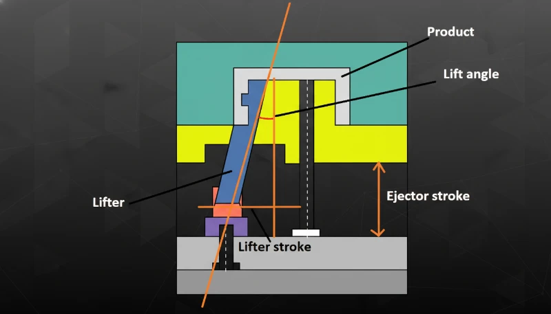
Per componenti complessi con sottosquadri o filettature interne servono estrattori inclinati, spine angolate o anime collassabili al posto degli espulsori diritti, oppure in aggiunta a essi. Questi meccanismi aumentano il costo dell’attrezzatura, ma sono necessari per pezzi che non possono essere riprogettati eliminando i sottosquadri. È essenziale pianificare la strategia di espulsione durante la revisione DFM, non scoprire in campionatura che il pezzo non si stacca.
Seguiamo una regola: se al primo campionamento il pezzo resta attaccato, non aggiungiamo semplicemente estrattori. Ricontrolliamo lo sformo. Nove volte su dieci la causa reale è lo sformo e aggiungere estrattori cura solo il sintomo.
"Un angolo di sformo3 di 0.5° è sufficiente per la maggior parte dei pezzi stampati a iniezione."True
Falso. Sebbene 0.5° possa essere sufficiente per pezzi molto semplici e poco profondi con cavità lucidate, il minimo standard del settore è 1° per lato. Le superfici testurizzate richiedono 2–3°. Valori inferiori comportano il rischio di incollaggio del pezzo, segni di trascinamento e danni allo stampo.
"La progettazione del sistema di raffreddamento rappresenta fino al 70% del tempo ciclo totale dello stampaggio a iniezione."False
Vero. La fase di raffreddamento domina il tempo di ciclo. L'ottimizzazione della disposizione dei canali di raffreddamento, mediante canali conformali, inserti in rame-berillio o interventi mirati sui punti caldi, può ridurre il tempo di ciclo del 20–40%, incidendo direttamente sul costo di produzione per pezzo.
Quale ruolo svolge la progettazione del sistema di raffreddamento nel tempo di ciclo e nella qualità?
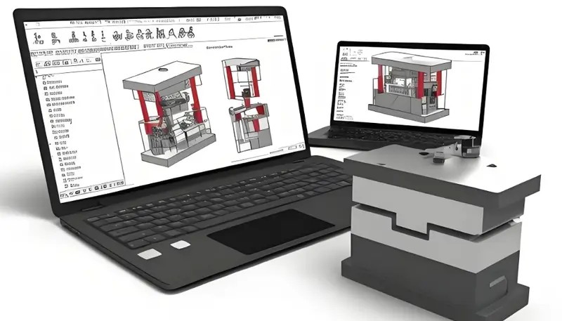
Il raffreddamento determina profitti o perdite nello stampaggio. Rappresenta il 50–70% del ciclo totale. Ridurre il raffreddamento di 2 secondi aumenta la produzione annua di migliaia di pezzi senza investimenti aggiuntivi in macchine o manodopera.
I principi fondamentali sono semplici: serve un raffreddamento uniforme dell’intero componente, con una portata sufficiente a mantenere costante la differenza di temperatura tra refrigerante e acciaio. Le difficoltà pratiche sono meno semplici. Anime e tasche profonde sono difficili da raggiungere con canali rettilinei forati. Le nervature sottili creano punti caldi non raggiungibili dal raffreddamento standard. Gli stampi multicavità richiedono un raffreddamento bilanciato di tutte le cavità: se una si raffredda più lentamente, determina il tempo ciclo dell’intero stampo.
Le soluzioni moderne includono canali di raffreddamento conformali (resi possibili da inserti stampo prodotti in 3D), leghe di rame-berillio nelle zone ad alta concentrazione di calore e spine termiche per anime profonde. Non sono soluzioni esotiche: sono prassi standard in qualsiasi officina stampi attenta al tempo ciclo. Se il costruttore propone soltanto canali rettilinei forati per un pezzo dalla geometria complessa, chiedi perché.
Anche la temperatura del fluido refrigerante è importante. La maggior parte degli stampi di produzione utilizza acqua a 15–25°C per i materiali amorfi (ABS, PC) e a 60–80°C per i materiali semicristallini (nylon, POM). Una temperatura troppo bassa genera tensioni residue; una troppo alta prolunga inutilmente il tempo ciclo. L’intervallo corretto dipende dal materiale e deve sempre essere documentato nella scheda dei parametri di processo prima dell’avvio della produzione.
In che modo la scelta del materiale e i requisiti di tolleranza influenzano la progettazione?
I requisiti relativi a materiali e tolleranze sono vincoli progettuali che influenzano ogni altra decisione nel processo di progettazione dello stampo. I tassi di ritiro variano in base al materiale: le resine amorfe come l’ABS si ritirano dello 0.4–0.7%, mentre i nylon semicristallini dell’1.0–2.5%. Questa sola differenza modifica le dimensioni delle cavità, quindi la scelta dell’acciaio dello stampo e infine il costo delle attrezzature. Comprendere presto queste relazioni tra materiali evita costose sorprese durante la campionatura e la produzione.
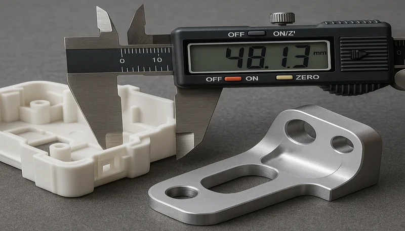
Le aspettative sulle tolleranze devono essere realistiche. Lo stampaggio a iniezione standard mantiene ±0.1mm per dimensioni inferiori a 25mm e ±0.3mm per dimensioni superiori a 100mm. Tolleranze più strette aumentano i costi, non solo per la precisione nella costruzione dello stampo, ma anche per il controllo del processo, l’ispezione e la possibile riduzione della finestra di processo. La prassi migliore è specificare tolleranze strette solo dove sono funzionalmente necessarie e adottare quelle standard in tutti gli altri punti.
I materiali caricati vetro si ritirano in modo differenziale, più lungo il flusso che trasversalmente. La cavità deve compensare e la finestra è più stretta. Per nylon caricato vetro con tolleranze strette, considerarlo nello stampo fin dall’inizio.
Quando le nervature di supporto superano le sezioni a parete spessa?
Le nervature di supporto sono superiori alle pareti spesse praticamente in ogni situazione: offrono la stessa rigidità con meno materiale e un raffreddamento più rapido. Le regole di progettazione sono semplici: lo spessore della nervatura deve essere pari al 50–60% della parete nominale, l’altezza non deve superare 3x la parete nominale e occorre almeno 0.5° di sformo per lato su ogni nervatura.
L’errore più comune è l’intersezione delle nervature. Quando due nervature si incrociano, lo spessore locale equivale alla somma dei due spessori e può creare un risucchio sulla superficie opposta. La soluzione è svuotare l’intersezione con un bossolo o una cavità, mantenendo lo spessore locale entro l’obiettivo ±10%.
Un altro errore comune consiste nel disporre le nervature troppo distanti. Se la distanza supera 3–4x lo spessore della parete, l’area non sostenuta tra le nervature può flettersi o deformarsi durante il raffreddamento. Una distanza minore aumenta il costo del materiale, ma riduce i problemi dimensionali. Per pezzi strutturali che devono mantenere una planarità rigorosa, uno schema di nervature con interasse 20–30mm è un ragionevole punto di partenza per una parete nominale di 2.5mm.
In sintesi: se una parete del pezzo supera 4mm, fermarsi e valutare se una parete più sottile con nervature possa svolgere la stessa funzione. Nella quasi totalità dei casi è possibile, migliorando anche il funzionamento dello stampo.
Il nostro reparto stampi interno di Shanghai produce oltre 100 set di stampi a iniezione al mese, con macchine CNC, elettroerosione a filo, incisori di precisione e taglio a filo lento. Ogni stampo segue un controllo qualità in 6 fasi, da IQC a OQC.
Domande frequenti sulla progettazione degli stampi a iniezione
| Elemento di progettazione | Requisito principale | Errore Comune |
|---|---|---|
| Spessore della parete | 2-3mm nominali, uniformità ±10% | Superamento di 4mm senza nervature |
| Angolo di sformo | ≥1° per lato (≥2° per superfici testurizzate) | Angolo di sformo nullo sulle pareti verticali |
| Parti bicolori | Riempimento bilanciato, linee di saldatura sicure | Posizionamento esclusivamente estetico |
| Raffreddamento | Uniforme in tutte le cavità | Foratura rettilinea solo su parti complesse |
Domande frequenti
Qual è il fattore più importante nella progettazione di uno stampo a iniezione?
L’uniformità dello spessore della parete è il fattore più importante nella progettazione di uno stampo a iniezione. Mantenere una costanza entro ±10% sull’intero componente previene i tre difetti produttivi più comuni: risucchi sulle superfici estetiche, deformazioni che portano le quote fuori specifica e vuoti interni che compromettono l’integrità strutturale. Lo spessore della parete determina direttamente la strategia di posizionamento dei punti di iniezione, il layout dei canali di raffreddamento e i tempi di ciclo ottenibili. L’analisi dello spessore è sempre il primo parametro valutato durante la revisione progettuale, perché ogni decisione successiva si basa su questo fondamento.
Quale angolo di sformo è necessario per i pezzi stampati a iniezione?
L’angolo di sformo minimo richiesto per lo stampaggio a iniezione è di 1° per lato su tutte le superfici verticali lisce; ciò vale senza eccezioni per ogni elemento verticale, comprese nervature, colonnine e pareti laterali. Le superfici testurizzate richiedono uno sformo molto maggiore, in genere 2–3° per lato, mentre texture più profonde o finiture lucide possono esigere angoli ancora superiori per garantire un distacco pulito. Uno sformo insufficiente fa aderire i pezzi alla cavità durante l’espulsione, causando segni di trascinamento, graffi superficiali e potenziali danni alle costose superfici dello stampo. Per dispositivi medici o componenti ottici in cui la qualità superficiale è essenziale, portare lo sformo a 1.5–2° anche sulle superfici lucidate offre un importante margine di sicurezza che previene problemi produttivi.
Qual è la tolleranza standard per i pezzi stampati a iniezione?
Lo stampaggio standard raggiunge tolleranze di ±0.1mm per dimensioni inferiori a 25mm e ±0.3mm oltre 100mm. Sono valori industriali mantenibili con costanza dalle attrezzerie qualificate senza controlli straordinari. Tolleranze più strette, fino a ±0.05mm per piccole dimensioni, sono possibili ma aumentano molto il costo dello stampo e restringono la finestra di processo, accentuando la sensibilità alle variazioni dei lotti e dei parametri macchina. La prassi migliore è specificarle solo sulle quote funzionali critiche, come sedi di cuscinetti o riferimenti di allineamento, lasciando tolleranze standard sulle altre per ottimizzare costo e qualità.
In che modo la posizione del punto di iniezione influisce sulla qualità del componente stampato a iniezione?
La posizione del punto di iniezione controlla direttamente tre aspetti critici di ogni pezzo stampato: l’avanzamento del riempimento del polimero nella cavità, la posizione in cui si formano le linee di giunzione quando fronti di flusso separati si incontrano e la lunghezza massima del flusso dal punto di iniezione alla parete più lontana della cavità. Un posizionamento errato crea sacche d’aria che causano riempimenti incompleti e bruciature, colloca le linee di giunzione in zone strutturali fortemente sollecitate creando punti deboli e genera una pressione di mantenimento irregolare che provoca incoerenza dimensionale. L’approccio ingegneristico corretto usa software di simulazione moldflow per ottimizzare la posizione del punto di iniezione in fase di progettazione, dando deliberatamente priorità al riempimento equilibrato della cavità e al posizionamento sicuro delle linee di giunzione rispetto al semplice occultamento del punto per ragioni estetiche.
Quale spessore di parete è raccomandato per i pezzi stampati a iniezione?
Per la maggior parte dei termoplastici tecnici, inclusi ABS, policarbonato e nylon, lo spessore nominale consigliato delle pareti strutturali è 2–3mm. Qualsiasi sezione oltre 4mm aumenta notevolmente il rischio di risucchi sulla superficie opposta, vuoti interni nella sezione spessa e tempi di raffreddamento prolungati che aumentano il costo unitario, senza miglioramenti proporzionali della resistenza meccanica. Invece di aumentare lo spessore per ottenere maggiore rigidità, i progettisti esperti usano nervature di supporto pari al 50–60% dello spessore nominale. Questa strategia collaudata riduce il consumo di materia prima, accorcia il ciclo del 15–25% e migliora sensibilmente la stabilità dimensionale tra i lotti.
Come può la progettazione dello stampo ridurre il tempo di ciclo dello stampaggio a iniezione?
Ottimizzare il layout del sistema di raffreddamento è la strategia di progettazione dello stampo più efficace per ridurre il tempo di ciclo, poiché la sola fase di raffreddamento rappresenta il 50–70% della durata totale del ciclo di stampaggio a iniezione. I canali di raffreddamento conformi che seguono il contorno del pezzo forniscono un’estrazione del calore significativamente più uniforme rispetto ai tradizionali canali diritti forati, mentre gli inserti in rame-berillio posizionati in aree a concentrazione termica come spine del nucleo e tasche profonde migliorano drasticamente l’efficienza di raffreddamento locale. Combinati con una distribuzione bilanciata del flusso del refrigerante in tutte le cavità degli stampi multi-cavità, queste strategie progettuali consentono costantemente riduzioni del tempo di ciclo del 20–40% senza alcun sacrificio della qualità del pezzo o della precisione dimensionale.
Quale acciaio per stampi è il migliore per stampi a iniezione ad alta precisione?
L’acciaio P20 pre-temprato a 28–32 HRC è la scelta standard per stampi di produzione fino a 500.000 cicli, offrendo un eccellente equilibrio tra lavorabilità, lucidabilità e costo. Per stampi di produzione ad alto volume che superano 1 milione di cicli, o stampi che lavorano materiali abrasivi riempiti di vetro o minerali, l’acciaio temprato H13 a 48–52 HRC offre una resistenza all’usura e una conducibilità termica significativamente superiori. Per componenti ottici a tolleranze strette o dispositivi medici che richiedono superfici specchiate e resistenza alla corrosione a lungo termine, l’acciaio inossidabile S136 è la scelta preferita nonostante il costo più elevato del materiale. La selezione dell’acciaio deve sempre corrispondere al volume di produzione totale previsto, al livello di abrasività del materiale e alla specifica di finitura superficiale richiesta.
Perché dovresti condurre una revisione DFM prima della costruzione dello stampo?
Una revisione completa della Progettazione per la Producibilità identifica incongruenze nello spessore delle pareti, angoli di sformo insufficienti, complessità dei sottosquadri che richiedono azioni laterali e posizionamento subottimale dei punti di iniezione prima che venga tagliato qualsiasi acciaio. Correggere questi problemi di progettazione durante la fase DFM costa circa dieci volte meno rispetto a modificare uno stampo di produzione completato tramite saldatura, rilavorazione o inserimento. Un’analisi DFM approfondita individua oltre l’80% dei potenziali problemi di produzione, inclusi molti problemi che emergerebbero solo durante il campionamento del primo articolo quando lo stampo è già costruito. La revisione DFM dovrebbe essere un passaggio obbligatorio per ogni progetto di stampo, indipendentemente dalla apparente semplicità, perché il costo della prevenzione è sempre inferiore al costo della correzione.
Pronti a ottimizzare il processo di progettazione dello stampo a iniezione?
La chiave per ottimizzare il processo di progettazione dello stampo è concentrarsi sullo spessore di parete, sul posizionamento del gate, sul raffreddamento e sulla selezione del materiale. Che tu stia partendo da uno schizzo concettuale o abbia bisogno di una revisione DFM su un progetto esistente, un team di ingegneria esperto può aiutarti a fare le cose bene fin dal primo tentativo.
Hai bisogno di una revisione DFM o di un preventivo per la progettazione dello stampo? I nostri project manager di lingua inglese rispondono entro 24 ore con osservazioni dettagliate, raccomandazioni sul processo e prezzi competitivi.
Richiedi un preventivo gratuito →
DFM: la DFM consiste nell'ottimizzare la geometria del componente e dello stampo durante la fase di progettazione per ridurre i difetti di produzione, abbassare il costo delle attrezzature e abbreviare i tempi di consegna. ↩
Spessore delle pareti: indica la distanza tra le superfici esterna e interna di un componente stampato; uno spessore uniforme previene avvallamenti, deformazioni e vuoti. ↩
Angolo di sformo: è una lieve inclinazione applicata alle superfici verticali di un componente stampato per consentirne l'espulsione pulita dalla cavità senza graffi o deformazioni. ↩