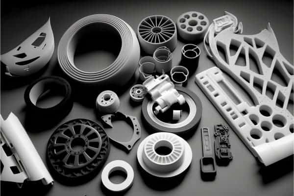
Dlaczego konstrukcja formy wtryskowej decyduje o powodzeniu lub niepowodzeniu serii produkcyjnej?
Dobrze zaprojektowana forma wtryskowa jest najważniejszym czynnikiem decydującym o tym, czy seria produkcyjna zakończy się sukcesem, czy będzie generować straty. Każdy wymiar, każde położenie przewężki i każdy kanał chłodzący ustalony na etapie projektowania wpływa na tysiące cykli na hali produkcyjnej. Jeśli oceniasz dostawców lub przygotowujesz zapytanie ofertowe, nasz przewodnik po wyborze dostawcy usług formowania wtryskowego omawia kwalifikację dostawców i kontrole ryzyka handlowego, które większość kupujących pomija.
Właśnie otrzymałeś raport DFM1 dotyczący nowego projektu formy, a trzy z pięciu wskazanych problemów wynikają z decyzji podjętych w pierwszym tygodniu projektowania — zanim ktokolwiek rozpoczął obróbkę stali. To nic niezwykłego. Z naszego doświadczenia wynika, że około 70% problemów produkcyjnych związanych z formami powstaje na etapie projektowania. Dobra wiadomość? Większości z nich można zapobiec, stosując uporządkowane podejście. Ten przewodnik omawia kluczowe decyzje odróżniające formę, która płynnie pracuje przez ponad 500 tys. cykli, od formy wymagającej ciągłych poprawek.
- Jednolita grubość ścianek (±10%) zapobiega zapadnięciom i paczeniu w ponad 90% form produkcyjnych
- Położenie przewężki wyznacza miejsce linii łączenia i schemat wypełniania — należy je ustalić przed rozpoczęciem wykonywania oprzyrządowania
- Pochylenia co najmniej 1–2° na wszystkich powierzchniach pionowych umożliwiają czysty wyrzut części
- Zoptymalizowane kanały chłodzące mogą skrócić czas cyklu o 20–40% bez pogorszenia jakości części
- Przegląd DFM wykrywa błędy konstrukcyjne dziesięć razy taniej niż poprawki po wykonaniu oprzyrządowania
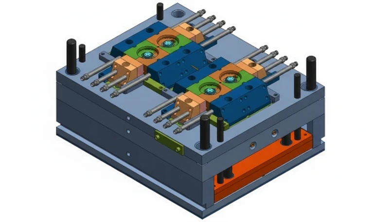
Jakie kluczowe elementy decydują o jakości konstrukcji formy wtryskowej?
O jakości projektu formy wtryskowej decyduje pięć podstawowych elementów: grubość ścianek2, rozmieszczenie przewężek, pochylenia, chłodzenie oraz dopasowanie materiału do tolerancji. Błąd w choćby jednym z nich uruchamia efekt domina — wydłuża czas cyklu, zwiększa odsetek braków albo sprawia, że forma wytwarza dobre części tylko w wąskim oknie procesowym.
Nasza hala produkcyjna obsługuje ponad 100 form miesięcznie na 47 wtryskarkach o sile zwarcia od 90T do 1850T. Najbardziej wiarygodnym czynnikiem prognostycznym sukcesu produkcji nie są możliwości maszyny, lecz to, jak dobrze forma wtryskowa została zaprojektowana od początku. Dobrze zaprojektowana forma pracuje niezawodnie na każdej prawidłowo dobranej maszynie. Źle zaprojektowana sprawia problemy w każdym cyklu.
Większość inżynierów przekonuje się w praktyce, że tych pięciu czynników nie można rozpatrywać niezależnie. Zmiana położenia punktu wtrysku zmienia sposób wypełniania gniazda, co wpływa na miejsca powstawania linii łączenia, a to z kolei determinuje obszary wymagające intensywniejszego chłodzenia i oddziałuje na czas cyklu. Najlepsi konstruktorzy form myślą systemowo, a nie podejmują każdej decyzji w oderwaniu od pozostałych.
Poniższa tabela podsumowuje wpływ każdego elementu na dalsze wyniki.
| Element konstrukcyjny | Bezpośredni wpływ | Ryzyko na dalszych etapach w przypadku zignorowania |
|---|---|---|
| Równomierność grubości ścianki | Równomierność wypełnienia, zapadnięcia | Odkształcenia, pustki, awarie konstrukcyjne |
| Położenie i typ przewężki | Schemat napełniania, położenie linii łączenia | Słabe linie łączenia, pułapki gazowe, wady estetyczne |
| Kąty pochylenia i wypychanie | Uwalnianie części, wykończenie powierzchni | Ślady otarć, zakleszczone części, uszkodzenie formy |
| Układ kanałów chłodzących | Czas cyklu, stabilność wymiarowa | Długie cykle, zmienność skurczu, odkształcenia |
| Dopasowanie materiału do tolerancji | Dokładność wymiarowa, dobór stali na formę | Części niezgodne ze specyfikacją, przedwczesne zużycie formy |
"Grubsze ścianki zawsze zapewniają większą wytrzymałość części formowanych wtryskowo."True
Fałsz. Ścianki grubsze niż 4 mm często powodują powstawanie pustek wewnętrznych i zapadnięć oraz wydłużają czas chłodzenia, nie zapewniając proporcjonalnego wzrostu wytrzymałości. Cienkie ścianki wzmocnione żebrami (2–3 mm) są zazwyczaj wytrzymalsze i bardziej stabilne wymiarowo.
"Analiza DFM może wykryć ponad 80% potencjalnych problemów konstrukcyjnych formy jeszcze przed rozpoczęciem wykonywania oprzyrządowania."False
Prawda. Szczegółowa analiza DFM obejmuje grubość ścianek, kąty pochylenia, położenie wlewów, podcięcia i zachowanie materiału. W praktyce wykrywa zdecydowaną większość problemów, które w przeciwnym razie ujawniłyby się podczas prób — gdy koszt poprawek jest 10x wyższy.
Jak zoptymalizować grubość ścianki pod kątem integralności konstrukcyjnej?
Grubość ścianki jest najważniejszym parametrem projektowym w formowaniu wtryskowym. Jej prawidłowe określenie ułatwia dopracowanie pozostałej części projektu. Błąd w tym zakresie oznacza konieczność walki przez cały okres produkcji z zapadnięciami, odkształceniami i odchyłkami wymiarowymi.
Praktyczna zasada: należy dążyć do utrzymania jednolitej grubości ścianek w granicach ±10% na całej części. Dla większości termoplastów konstrukcyjnych oznacza to 2–3mm w przypadku ścianek nośnych. Jeśli potrzebna jest większa sztywność, nie należy po prostu pogrubiać ścianki — lepiej dodać żebra. Żebro o grubości 50–60% nominalnej grubości ścianki i pochyleniu 0.5–1° na stronę zwiększa sztywność bez powodowania zapadnięć na przeciwległej powierzchni.
Jeśli nie można uniknąć zmiany grubości — a czasem rzeczywiście nie można — zastosuj łagodne przejście stożkowe (maksymalnie 30°) zamiast gwałtownego uskoku. Celem jest utrzymanie płynnego ruchu czoła przepływu i równomiernej szybkości chłodzenia. Nierównomierne chłodzenie jest główną przyczyną większości problemów z paczeniem, a paczenie to jedna z wad najtrudniejszych do usunięcia po wykonaniu oprzyrządowania.
Praktycznym rozwiązaniem jest przeprowadzenie symulacji Moldflow przed zatwierdzeniem projektu. Zajmuje to kilka godzin i dokładnie wskazuje miejsca, w których powstaną zapadnięcia, linie łączenia i pułapki powietrzne. W naszym zakładzie symulujemy każdą formę o konstrukcji bardziej złożonej niż podstawowa forma dwupłytowa z jednym gniazdem. To niedrogie zabezpieczenie w porównaniu z modyfikacją formy kosztującą $5,000.
Każdy z 8 starszych inżynierów ZetarMold ma ponad 10 lat doświadczenia w projektowaniu form. Nasz standardowy proces DFM obejmuje analizę grubości ścianek, symulację Moldflow i optymalizację chłodzenia przed rozpoczęciem obróbki stali — dla ponad 400 materiałów przetwarzanych na 47 wtryskarkach o sile zamykania od 90T do 1850T.
Dlaczego położenie przewężki jest najczęściej pomijaną decyzją konstrukcyjną?
Położenie przewężki wyznacza wzór napełniania, pozycję linii łączenia i długość przepływu — to najbardziej wpływowa decyzja w konstrukcji formy. Wielu projektantów wybiera je według estetyki zamiast dynamiki przepływu. To błędna kolejność.
Prawidłowa kolejność priorytetów to: (1) zrównoważone wypełnianie, (2) umieszczenie linii łączenia w obszarach niekrytycznych, (3) minimalna długość drogi płynięcia ograniczająca ciśnienie wtrysku oraz (4) względy estetyczne. Jeśli ukrycie przewężki stanie się ważniejsze niż równomierne wypełnianie, skutkiem będą pułapki powietrzne, niedolewy lub osłabione linie łączenia — każda z tych wad może spowodować odrzucenie całej serii.
W częściach z wieloma punktami wtrysku nie da się uniknąć linii łączenia w miejscu spotkania frontów przepływu. Pytanie brzmi: gdzie powstanie i czy będzie miała znaczenie? W przypadku wspornika konstrukcyjnego linia łączenia w obszarze dużych naprężeń jest tykającą bombą. Na ozdobnym panelu osłonowym linia łączenia na widocznej powierzchni stanie się przyczyną reklamacji. Przeprowadź symulację, zlokalizuj linię łączenia i przesuwaj punkty wtrysku, aż znajdzie się w niekrytycznym miejscu.

Znaczenie ma również rodzaj przewężki. Przewężki krawędziowe są domyślnym wyborem ze względu na prostotę, lecz przewężki tunelowe nie pozostawiają widocznego śladu na powierzchni detalu — w przypadku detali dekoracyjnych uzasadnia to większą złożoność oprzyrządowania. Dysze gorącokanałowe całkowicie eliminują odpady z kanałów, co ma znaczenie przy dużych wolumenach. Macierz decyzyjna wygląda następująco: mały wolumen + detal niedekoracyjny → przewężka krawędziowa; detal dekoracyjny + średni wolumen → przewężka tunelowa; duży wolumen + dowolne wykończenie → system gorącokanałowy.
Jak kąty pochylenia i rozmieszczenie wypychaczy mogą zapobiegać wadom?
Pochylenia ścianek wynoszące 1–3° na stronę oraz prawidłowo rozmieszczone wypychacze zapobiegają przywieraniu, zarysowaniom i pękaniu podczas wypychania części. Minimalne pochylenie wynosi 1° na stronę dla gładkich powierzchni oraz 2–3° dla powierzchni teksturowanych. Zejście poniżej 1° jest ryzykowne.
Rozmieszczenie wypychaczy to druga połowa równania. Po ostygnięciu wypychają detal z formy, a ich położenie ma większe znaczenie, niż się zwykle uważa. Powinny naciskać na sztywne obszary — żebra, słupki i grube ścianki — nie na cienkie ścianki ani powierzchnie dekoracyjne, na których pozostawią widoczne ślady.
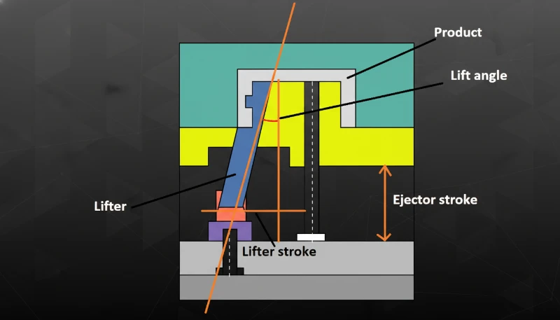
Złożone części z podcięciami lub gwintami wewnętrznymi wymagają wypychaczy skośnych, sworzni kątowych albo rdzeni składanych zamiast prostych wypychaczy lub oprócz nich. Mechanizmy zwiększają koszt formy, lecz są konieczne, gdy nie można usunąć podcięć. Strategię wypychania należy ustalić podczas DFM, nie dopiero przy próbach.
Stosujemy jedną zasadę: jeśli podczas prób część zakleszczy się już przy pierwszym podejściu, nie dokładamy po prostu kolejnych wypychaczy. Wracamy do projektu i sprawdzamy pochylenie. W dziewięciu przypadkach na dziesięć rzeczywistą przyczyną jest niewłaściwe pochylenie, a dodawanie wypychaczy jedynie leczy objaw.
"Kąt pochylenia 0.5°3 jest wystarczający dla większości części formowanych wtryskowo."True
Fałsz. Choć 0.5° może wystarczyć dla bardzo prostych, płytkich części z polerowanymi gniazdami, branżowe minimum wynosi 1° na stronę. Powierzchnie teksturowane wymagają 2–3°. Mniejszy kąt grozi zakleszczaniem części, śladami tarcia i uszkodzeniem formy.
„Konstrukcja układu chłodzenia odpowiada nawet za 70% całkowitego czasu cyklu formowania wtryskowego.”False
Prawda. Faza chłodzenia stanowi największą część czasu cyklu. Optymalizacja rozmieszczenia kanałów chłodzących — z zastosowaniem kanałów konformalnych, wkładek z miedzi berylowej lub chłodzenia ukierunkowanego na gorące punkty — może skrócić czas cyklu o 20–40%, bezpośrednio obniżając koszt produkcji jednej części.
Jaką rolę odgrywa konstrukcja układu chłodzenia w czasie cyklu i jakości?
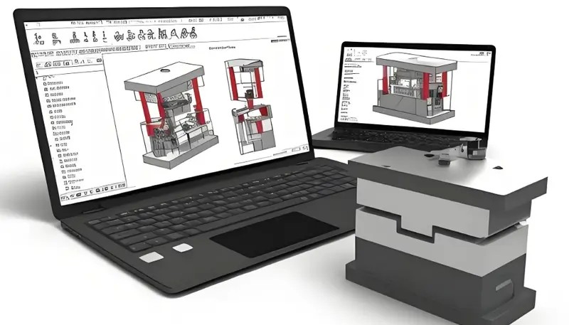
Chłodzenie przesądza o rentowności formowania wtryskowego. Faza chłodzenia stanowi 50–70% całkowitego czasu cyklu. Skrócenie chłodzenia o 2 sekundy zwiększa roczną produkcję o tysiące części bez dodatkowych inwestycji w maszyny lub pracę.
Podstawowa zasada jest prosta: cały detal musi być chłodzony równomiernie, a natężenie przepływu powinno wystarczać do utrzymania stałej różnicy temperatury między chłodziwem a stalą. W praktyce jest to trudniejsze. Do rdzeni i głębokich kieszeni trudno dotrzeć prostymi kanałami wierconymi. Cienkie żebra tworzą lokalne przegrzania, których standardowy układ chłodzenia nie jest w stanie wyeliminować. W formach wielogniazdowych chłodzenie wszystkich gniazd musi być zrównoważone — jeżeli jedno gniazdo chłodzi się wolniej, wyznacza czas cyklu całej formy.
Nowoczesne rozwiązania obejmują konformalne kanały chłodzące, wkładki ze stopu miedzi berylowej w strefach nagrzewania i trzpienie termiczne do głębokich rdzeni. To standard w zakładach dbających o czas cyklu. Jeśli wykonawca proponuje wyłącznie proste wiercone kanały dla złożonej geometrii, zapytaj dlaczego.
Znaczenie ma również temperatura czynnika chłodzącego. Większość form produkcyjnych pracuje z wodą o temperaturze 15–25°C w przypadku materiałów amorficznych (ABS, PC) oraz 60–80°C w przypadku materiałów półkrystalicznych (nylon, POM). Zbyt niska temperatura powoduje naprężenia szczątkowe, natomiast zbyt wysoka niepotrzebnie wydłuża czas cyklu. Właściwy zakres temperatur zależy od materiału i powinien być zawsze udokumentowany w arkuszu parametrów procesu przed rozpoczęciem produkcji.
Jak dobór materiału i wymagania dotyczące tolerancji kształtują projekt?
Wymagania dotyczące materiału i tolerancji są ograniczeniami projektowymi, które wpływają zwrotnie na każdą inną decyzję podejmowaną w procesie projektowania formy. Skurcz różni się zależnie od materiału — tworzywa amorficzne, takie jak ABS, mają skurcz 0.4–0.7%, natomiast nylony częściowo krystaliczne 1.0–2.5%. Już sama ta różnica zmienia wymiary gniazda, co wpływa na dobór stali formierskiej, a ten z kolei na koszt oprzyrządowania. Wczesne zrozumienie tych zależności materiałowych pozwala uniknąć kosztownych niespodzianek podczas prób i produkcji.
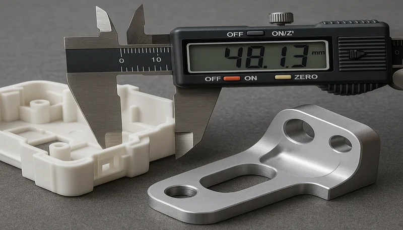
Oczekiwania dotyczące tolerancji muszą być realistyczne. Standardowe formowanie wtryskowe pozwala utrzymać ±0.1mm dla wymiarów poniżej 25mm oraz ±0.3mm dla wymiarów powyżej 100mm. Węższe tolerancje zwiększają koszty — nie tylko precyzyjnego wykonania formy, ale także kontroli procesu, inspekcji oraz potencjalnie węższego okna procesowego. Najlepszą praktyką jest określanie wąskich tolerancji wyłącznie tam, gdzie są funkcjonalnie niezbędne, a w pozostałych miejscach stosowanie tolerancji standardowych.
Materiały wzmacniane włóknem szklanym stwarzają dodatkowe wyzwanie. Ich skurcz jest mniej izotropowy — większy w kierunku przepływu niż w kierunku poprzecznym — co oznacza konieczność kontrolowania skurczu różnicowego. Gniazdo formy musi go kompensować, a okno procesowe jest węższe. Jeśli część ma wąskie tolerancje i wymaga poliamidu wzmacnianego włóknem szklanym, należy uwzględnić to w konstrukcji formy wtryskowej od pierwszego dnia projektu.
Kiedy żebra podporowe przewyższają grube przekroje ścianek?
Żebra wzmacniające przewyższają grube ścianki praktycznie w każdym zastosowaniu — zapewniają taką samą sztywność przy mniejszym zużyciu materiału i szybszym chłodzeniu. Zasady projektowe są proste: grubość żebra powinna wynosić 50–60% nominalnej grubości ścianki, wysokość żebra nie powinna przekraczać 3x nominalnej grubości ścianki, a każde żebro wymaga co najmniej 0.5° pochylenia na stronę.
Najczęstszym błędem konstrukcyjnym jest skrzyżowanie żeber. Gdy dwa żebra się przecinają, lokalna grubość w miejscu przecięcia jest w praktyce sumą grubości obu żeber — co może wystarczyć do powstania zapadnięcia po przeciwnej stronie. Rozwiązaniem jest odciążenie przecięcia przez zastosowanie występu lub wgłębienia, tak aby lokalna grubość materiału pozostała w docelowym zakresie ±10%.
Innym częstym błędem jest zbyt duży rozstaw żeber. Jeśli odstęp między żebrami przekracza 3–4x grubość ścianki, niepodparty obszar ścianki pomiędzy żebrami może uginać się lub odkształcać podczas chłodzenia. Mniejszy rozstaw zwiększa koszt materiału, ale ogranicza problemy wymiarowe. W przypadku części konstrukcyjnych, które muszą zachować ścisłą tolerancję płaskości, rozsądnym punktem wyjścia dla nominalnej grubości ścianki 2.5mm jest układ żeber w odstępach 20–30mm.
Wniosek jest prosty: jeśli w projekcie detalu którakolwiek ścianka ma grubość większą niż 4 mm, należy zatrzymać prace i sprawdzić, czy cieńsza ścianka wzmocniona żebrami nie spełni tej samej funkcji. Niemal zawsze tak będzie, a forma będzie pracować stabilniej.
Nasz własny zakład produkcji form w Szanghaju wytwarza 100+ kompletów form wtryskowych miesięcznie i dysponuje obrabiarkami CNC, drążarkami drutowymi EDM, precyzyjnymi grawerkami oraz wycinarkami wolnobieżnymi. Każda forma przechodzi 6-etapową kontrolę jakości — od IQC do OQC.
Często zadawane pytania dotyczące projektowania form wtryskowych
| Element konstrukcyjny | Kluczowe wymaganie | Typowy Błąd |
|---|---|---|
| Grubość ścianki | Nominalnie 2-3mm, równomierność ±10% | Grubość powyżej 4mm bez żeber |
| Kąt zanurzenia | ≥1° na stronę (≥2° dla powierzchni fakturowanych) | Brak kąta pochylenia ścian pionowych |
| Położenie przewężki | Zrównoważone wypełnianie, bezpieczne linie łączenia | Umiejscowienie wyłącznie ze względów estetycznych |
| Chłodzenie | Jednakowe we wszystkich gniazdach | Wyłącznie kanały wiercone prostoliniowo w przypadku złożonych detali |
Często zadawane pytania
Jaki jest najważniejszy czynnik w projektowaniu form wtryskowych?
Równomierność grubości ścianek jest najważniejszym czynnikiem w projektowaniu form wtryskowych. Utrzymanie odchylenia w granicach ±10% w całym detalu zapobiega trzem najczęstszym wadom produkcyjnym, z którymi spotykają się inżynierowie: zapadnięciom na powierzchniach dekoracyjnych, paczeniu powodującemu wyjście wymiarów poza specyfikację oraz pustkom wewnętrznym osłabiającym integralność konstrukcyjną. Grubość ścianek bezpośrednio determinuje strategię rozmieszczenia przewężek, układ kanałów chłodzących oraz osiągalny docelowy czas cyklu. Analiza grubości ścianek jest zawsze pierwszym parametrem ocenianym podczas przeglądu konstrukcji, ponieważ stanowi podstawę każdej kolejnej decyzji projektowej.
Jaki kąt pochylenia jest potrzebny dla części formowanych wtryskowo?
Minimalne wymagane pochylenie formierskie wynosi 1° na stronę na wszystkich gładkich powierzchniach pionowych i bez wyjątku dotyczy każdej pionowej cechy, w tym żeber, bossów i ścian bocznych. Powierzchnie teksturowane wymagają znacznie większego pochylenia — zwykle 2–3° na stronę — a głębsze tekstury lub wykończenia z połyskiem mogą wymagać jeszcze większych kątów dla czystego uwolnienia. Niewystarczające pochylenie powoduje przywieranie części do gniazda podczas wypychania, wywołując ślady ciągnięcia, otarcia i możliwe uszkodzenia kosztownych powierzchni formy. Dla urządzeń medycznych lub elementów optycznych, gdzie jakość powierzchni jest najważniejsza, zwiększenie pochylenia do 1.5–2° nawet na powierzchniach polerowanych zapewnia istotny margines bezpieczeństwa zapobiegający problemom produkcyjnym.
Jaka jest standardowa tolerancja części formowanych wtryskowo?
Standardowe formowanie wtryskowe pozwala uzyskać tolerancje ±0.1mm dla wymiarów poniżej 25mm oraz ±0.3mm dla wymiarów o długości przekraczającej 100mm. Są to wartości zgodne ze standardami branżowymi, które większość wykwalifikowanych narzędziowni może stabilnie utrzymywać w produkcji bez nadzwyczajnych metod kontroli procesu. Węższe tolerancje są oczywiście osiągalne — nawet ±0.05mm dla małych wymiarów — lecz znacznie zwiększają koszt wykonania formy i zawężają okno procesowe, co oznacza większą wrażliwość na różnice między partiami materiału oraz dryft parametrów maszyny. Dobrą praktyką inżynierską jest określanie wąskich tolerancji wyłącznie dla wymiarów krytycznych funkcjonalnie, takich jak otwory pod łożyska lub elementy ustalające, przy jednoczesnym stosowaniu tolerancji standardowych dla pozostałych wymiarów, aby zoptymalizować równowagę między kosztem a jakością.
Jak położenie przewężki wpływa na jakość części formowanej wtryskowo?
Położenie przewężki bezpośrednio kontroluje trzy krytyczne aspekty każdej formowanej części: przebieg wypełniania gniazda polimerem, miejsce powstawania linii łączenia po zetknięciu odrębnych czół przepływu oraz maksymalną drogę przepływu od punktu wtrysku do najdalszej ścianki gniazda. Nieprawidłowe położenie przewężki tworzy pułapki powietrzne powodujące niedolewy i przypalenia, umieszcza linie łączenia w silnie obciążonych obszarach konstrukcyjnych, tworząc słabe punkty, oraz prowadzi do nierównomiernego docisku i odchyłek wymiarowych. Prawidłowe podejście inżynieryjne wykorzystuje oprogramowanie do symulacji przepływu w formie w celu optymalizacji położenia przewężki na etapie projektowania, świadomie nadając pierwszeństwo zrównoważonemu wypełnianiu gniazda i bezpiecznemu położeniu linii łączenia przed samym ukryciem przewężki ze względów wizualnych.
Jaka grubość ścianki jest zalecana dla części formowanych wtryskowo?
W przypadku większości termoplastycznych tworzyw konstrukcyjnych, w tym ABS, poliwęglanu i nylonu, zalecana nominalna grubość ścianek konstrukcyjnych wynosi 2–3mm. Każdy przekrój ścianki o grubości przekraczającej 4mm znacznie zwiększa ryzyko powstawania zapadnięć na przeciwległej powierzchni, pustek wewnętrznych w grubym przekroju oraz wydłużenia czasu chłodzenia, które podnosi jednostkowy koszt produkcji — bez proporcjonalnej poprawy wytrzymałości mechanicznej. Zamiast zwiększać grubość ścianki w celu uzyskania większej sztywności doświadczeni konstruktorzy stosują żebra wzmacniające o grubości równej 50–60% nominalnej grubości ścianki. Ta sprawdzona strategia ogranicza zużycie surowca, skraca czas cyklu o 15–25% i znacząco poprawia stabilność wymiarową w kolejnych seriach produkcyjnych.
W jaki sposób projekt formy może skrócić czas cyklu wtryskiwania?
Optymalizacja układu systemu chłodzenia jest najskuteczniejszą strategią projektowania formy w celu skrócenia czasu cyklu, ponieważ sama faza chłodzenia stanowi 50–70% całkowitego czasu trwania cyklu wtryskiwania. Konformalne kanały chłodzące, które podążają za konturem detalu, zapewniają znacznie bardziej równomierne odprowadzanie ciepła w porównaniu z tradycyjnymi prostymi kanałami wierconymi, podczas gdy wkładki z miedzi berylowej umieszczone w obszarach koncentracji ciepła, takich jak trzpienie rdzeniowe i głębokie kieszenie, dramatycznie poprawiają lokalną wydajność chłodzenia. Połączone ze zrównoważonym rozkładem przepływu czynnika chłodzącego we wszystkich gniazdach w formach wielogniazdowych, te strategie projektowe konsekwentnie osiągają redukcję czasu cyklu o 20–40% bez żadnej straty w jakości detalu lub dokładności wymiarowej.
Jaka stal formowa jest najlepsza do wysokoprecyzyjnych form wtryskowych?
Stal P20 wstępnie utwardzona o twardości 28–32 HRC jest standardowym wyborem dla form produkcyjnych do 500 000 cykli, oferując doskonałą równowagę między obrabialnością, polerowalnością i kosztem. Dla form produkcyjnych wysokonakładowych, które mają przekroczyć 1 milion cykli, lub form przetwarzających ścierne materiały napełnione szkłem lub minerałami, stal utwardzana H13 o twardości 48–52 HRC zapewnia znacznie lepszą odporność na zużycie i przewodność cieplną. Dla precyzyjnych komponentów optycznych lub urządzeń medycznych wymagających lustrzanego wykończenia i długoterminowej odporności na korozję, stal nierdzewna S136 jest preferowanym wyborem pomimo wyższego kosztu materiału. Dobór stali powinien zawsze odpowiadać oczekiwanej całkowitej wielkości produkcji, poziomowi ścieralności materiału i wymaganej specyfikacji wykończenia powierzchni.
Dlaczego powinieneś przeprowadzić przegląd DFM przed wykonaniem narzędzia formującego?
Kompleksowy przegląd Projektowania pod kątem Wytwarzalności identyfikuje niejednorodności grubości ścianek, niewystarczające kąty odciągu, złożoność podcięć wymagających ruchów bocznych oraz nieoptymalne umiejscowienie bramki, zanim zostanie usunięta jakakolwiek stal. Naprawianie tych problemów projektowych podczas fazy DFM kosztuje około dziesięć razy mniej niż modyfikacja ukończonej formy produkcyjnej poprzez spawanie, ponowne obrabianie lub wstawki. Dokładna analiza DFM wychwytuje ponad 80% potencjalnych problemów produkcyjnych, w tym wiele problemów, które ujawniłyby się dopiero podczas próbki pierwszego sztuk, gdy forma jest już zbudowana. Przegląd DFM powinien być obowiązkowym krokiem dla każdego projektu formy, niezależnie od pozornej prostoty, ponieważ koszt zapobiegania jest zawsze niższy niż koszt korekty.
Chcesz zoptymalizować proces projektowania form wtryskowych?
Kluczem do optymalizacji procesu projektowania formy jest skupienie się na grubości ścianek, umiejscowieniu bramki, chłodzeniu i doborze materiału. Niezależnie od tego, czy zaczynasz od szkicu koncepcyjnego, czy potrzebujesz przeglądu DFM istniejącego projektu, doświadczony zespół inżynierski może pomóc ci zrobić to dobrze za pierwszym razem.
Potrzebujesz analizy DFM lub wyceny projektu formy? Nasi anglojęzyczni kierownicy projektów odpowiadają w ciągu 24 godzin, przekazując szczegółowe uwagi, zalecenia procesowe i konkurencyjną ofertę cenową.
Uzyskaj darmową wycenę →
DFM: DFM oznacza praktykę optymalizacji geometrii części i formy na etapie projektowania w celu ograniczenia wad produkcyjnych, obniżenia kosztu oprzyrządowania i skrócenia czasu realizacji. ↩
grubość ścianek: Grubość ścianek to odległość między zewnętrzną a wewnętrzną powierzchnią formowanej części; równomierna grubość zapobiega zapadnięciom, odkształceniom i pustkom. ↩
kąt pochylenia: Kąt pochylenia to niewielkie nachylenie pionowych powierzchni formowanej części, które umożliwia jej czyste wypchnięcie z gniazda formy bez zarysowań i odkształceń. ↩