...

射出成形金型設計プロセスの改善方法

• ZetarMold Engineering Guide
• Plastic Injection Mold Manufacturing Since 2005
• Built by ZetarMold engineers for buyers comparing mold and molding solutions.

Why Does Injection Mold Design Make or Break Your Production Run?

A well-designed injection mold is the single most important factor in whether your production run succeeds or bleeds money. Every dimension, every gate location, every cooling channel you decide in the design phase echoes through thousands of cycles on the shop floor. If you are evaluating suppliers or preparing an RFQ, our injection molding supplier sourcing guide walks you through vendor qualification and commercial risk checks that most buyers overlook.

射出成形金型冷却システムの種類:完全ガイド | ZetarMold DFM1 report back on a new mold project, and three of the five flagged issues trace back to decisions made in the first week of design — before anyone touched steel. That’s not unusual. In our experience, roughly 70% of mold-related production problems originate in the design phase. The good news? Most of them are preventable if you follow a structured approach. This guide walks through the key decisions that separate a mold that runs smoothly for 500K+ cycles from one that needs constant rework.

要点
  • Uniform wall thickness (±10%) prevents sink marks and warpage in 90%+ of production molds
  • Gate location determines weld line position and fill pattern — decide before tooling starts
  • Draft angles of 1–2° minimum on all vertical surfaces enable clean part ejection
  • Optimized cooling channels can cut cycle time by 20–40% without sacrificing part quality
  • DFM review catches design flaws 10x cheaper than post-tooling fixes
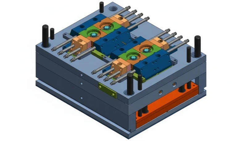
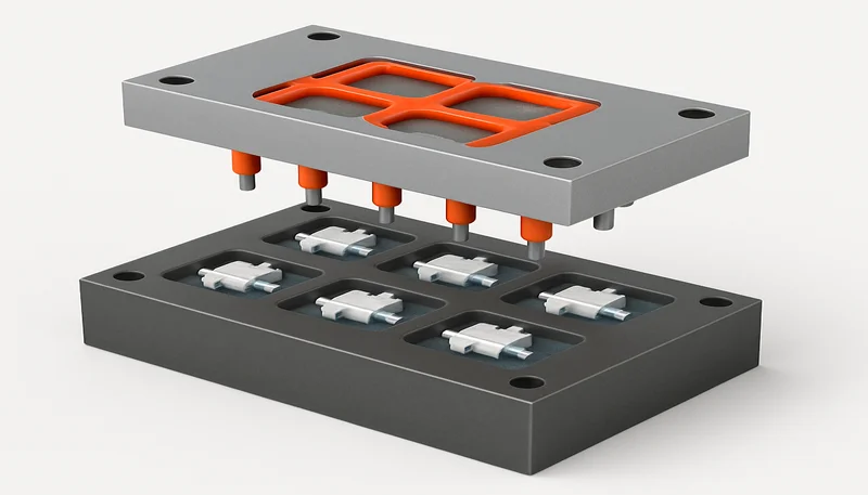
3D design of plastic injection mold
3D CAD model of an injection

What Are the Core Elements That Determine Injection Mold Design Quality?

Injection mold design quality is determined by five core elements: 肉厚2, gate placement, draft, cooling, and material-tolerance alignment. Get any one of these wrong, and the dominoes start falling — longer cycle times, higher scrap rates, or a mold that produces good parts only within a narrow processing window.

Our production floor supports 100+ molds per month across 47 injection molding machines ranging from 90T to 1850T. The most consistent predictor of production success is not machine capability; it is how well the 射出成形金型 was designed from the start. A well-designed mold runs reliably on any properly sized machine. A poorly designed mold fights you on every cycle.

Here’s the thing most engineers learn the hard way: these five factors aren’t independent. Moving a gate changes the fill pattern, which affects where weld lines form, which changes where you need cooling focus, which impacts cycle time. The best mold designers think in systems, not in isolated decisions.

The table below summarizes how each element connects to downstream outcomes.

Core Mold Design Elements and Their Downstream Impact
Design Element Direct Impact Downstream Risk if Ignored
Wall thickness uniformity Fill balance, sink marks Warpage, voids, structural failure
Gate location and type Fill pattern, weld line position Weak weld lines, gas traps, cosmetic defects
Draft angles and ejection Part release, surface finish Scuff marks, stuck parts, mold damage
冷却水路レイアウト Cycle time, dimensional stability Long cycles, shrinkage variation, warpage
Material-tolerance match Dimensional accuracy, mold steel selection Out-of-spec parts, premature mold wear

“Thicker walls always produce stronger injection molded parts.”

False. Walls thicker than 4mm often create internal voids, sink marks, and longer cooling times without proportional strength gains. Rib-reinforced thin walls (2–3mm) are typically stronger and more dimensionally stable.

“A DFM review can identify over 80% of potential mold design issues before tooling begins.”

True. A thorough DFM analysis examines wall thickness, draft, gate placement, undercuts, and material behavior. In practice, it catches the vast majority of issues that would otherwise surface during sampling — when fixes cost 10x more.

How Do You Optimize Wall Thickness for Structural Integrity?

Wall thickness is the single most influential design parameter in injection molding. Get it right, and the rest of the design falls into place more easily. Get it wrong, and you will spend the entire production run fighting sink marks, warpage, and dimensional drift.

The rule of thumb: aim for uniform wall thickness within ±10% across the entire part. For most engineering thermoplastics, that means 2–3mm for structural walls. If you need more rigidity, don’t just thicken the wall — add ribs instead. A rib at 50–60% of the nominal wall thickness, with a draft of 0.5–1° per side, adds stiffness without creating sink marks on the opposite surface.

When you can’t avoid a thickness transition — and sometimes you genuinely can’t — use a gradual taper (30° maximum) rather than an abrupt step change. The goal is to keep the flow front moving smoothly and the cooling rate even. Uneven cooling is the root cause of most warpage issues, and warpage is one of the hardest defects to fix after tooling.

One practical approach: run a moldflow simulation before finalizing the design. It takes a few hours and tells you exactly where sink marks, weld lines, and air traps will form. In our shop, we simulate every mold with complexity above a basic two-plate, single-cavity design. It’s cheap insurance compared to a $5,000 mold modification.

🏭 ZetarMold Factory Insight
ZetarMold’s 8 senior engineers each bring 10+ years of mold design experience. Our standard DFM process includes wall thickness analysis, moldflow simulation, and cooling optimization before any steel is cut — covering 400+ materials across 47 injection molding machines from 90T to 1850T.

Why Is Gate Location the Most Overlooked Design Decision?

Gate location determines your fill pattern, weld-line position, and flow length — it is the single most impactful decision in mold design. Most designers pick gate location based on aesthetics rather than fill dynamics. That’s backwards.

The correct priority is: (1) balanced fill, (2) weld line placement in non-critical areas, (3) minimal flow length to reduce injection pressure, and (4) aesthetic concerns. If you prioritize hiding the gate over fill balance, you’ll end up with trapped air, short shots, or weak weld lines — any of which can scrap the entire run.

For parts with multiple gates, the weld line where flow fronts meet is inevitable. The question is: where does it form, and does it matter? On a structural bracket, a weld line in a high-stress area is a ticking time bomb. On a cosmetic cover panel, a weld line on a visible surface is a customer complaint. Run the simulation, find the weld line, and move the gates until it lands somewhere harmless.

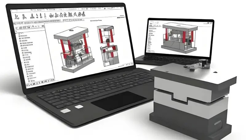
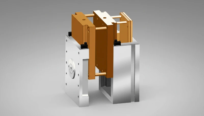
3D plastic injection mold design
Gate location analysis in 3D mold

Gate type matters too. Edge gates are the default for simplicity, but submarine gates leave no visible mark on the part surface — worth the extra tooling complexity for cosmetic parts. Hot runner drops eliminate runner waste entirely, which matters at high volumes. The decision matrix looks like this: low volume + non-cosmetic → edge gate; cosmetic + medium volume → submarine; high volume + any finish → hot runner.

How Can Draft Angles and Ejector Pin Placement Prevent Defects?

Draft angles of 1–3° per side and properly positioned ejector pins prevent sticking, scuffing, and cracking during part ejection. The minimum draft is 1° per side for smooth surfaces, and 2–3° for textured surfaces. Going below 1° is gambling.

Ejector pin placement is the other half of the equation. Pins push the part out of the mold after it cools, and where you put them matters more than most people think. The pins need to push on stiff areas of the part — ribs, bosses, thick wall sections — not on thin walls or cosmetic surfaces where they’ll leave visible marks.

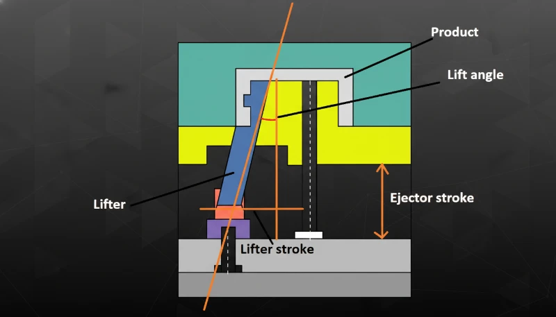
For complex parts with undercuts or internal threads, you’ll need lifters, angle pins, or collapsible cores instead of (or in addition to) straight ejector pins. These mechanisms add tooling cost but are necessary for parts that can’t be redesigned to eliminate undercuts. The key is to plan ejection strategy during DFM review, not discover during sampling that the part won’t release.

One rule we follow: if the part sticks on the first try during sampling, we don’t just add more ejector pins. We go back and check the draft. Nine times out of ten, a draft issue is the real cause, and adding pins is just treating the symptom.

“A 0.5° 抜き勾配3 is sufficient for most injection molded parts.”

False. While 0.5° may work for very simple, shallow parts with polished cavities, the industry standard minimum is 1° per side. Textured surfaces require 2–3°. Anything less risks part sticking, drag marks, and mold damage.

“Cooling system design accounts for up to 70% of the total injection molding cycle time.”

True. The cooling phase dominates cycle time. Optimizing cooling channel layout — using conformal channels, beryllium copper inserts, or hot spots targeting — can reduce cycle time by 20–40%, directly impacting production cost per part.

What Role Does Cooling System Design Play in Cycle Time and Quality?

射出成形金型設計
Cooling channel design for molds

Cooling is where money is made or lost in injection molding. The cooling phase accounts for 50–70% of total cycle time. Shave 2 seconds off cooling, and you’ve just increased your annual output by thousands of parts with zero additional investment in machines or labor.

The fundamentals are straightforward: you need uniform cooling across the entire part, with enough flow rate to maintain a consistent temperature differential between the coolant and the steel. The practical challenges are less straightforward. Cores and deep pockets are hard to reach with straight drilled channels. Thin ribs create hot spots that standard cooling can’t touch. Multi-cavity molds need balanced cooling across all cavities — if one cavity cools slower, it governs the cycle time for the entire mold.

Modern solutions include conformal cooling channels (made possible by 3D-printed mold inserts), beryllium copper alloys in heat-concentrated areas, and thermal pins for deep cores. These aren’t exotic — they’re standard practice in any mold shop that cares about cycle time. If your moldmaker proposes only straight drilled channels on a part with complex geometry, ask why.

The coolant temperature matters too. Most production molds run with water at 15–25°C for amorphous materials (ABS, PC) and 60–80°C for semi-crystalline materials (nylon, POM). Running too cold creates residual stress; running too hot extends cycle time unnecessarily. The correct temperature window is material-specific and should always be documented in the process parameters sheet before production begins.

How Do Material Selection and Tolerance Requirements Shape Your Design?

Material and tolerance requirements are design constraints that feed back into every other decision you make during the mold design process. Shrinkage rates differ by material — amorphous resins like ABS shrink 0.4–0.7%, while semi-crystalline nylons shrink 1.0–2.5%. That difference alone changes cavity dimensions, which changes mold steel selection, which changes tooling cost. Understanding these material relationships early prevents expensive surprises during sampling and production.

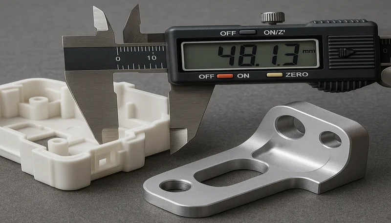
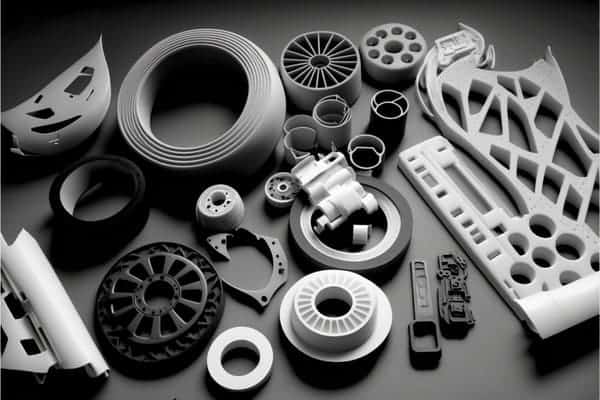
Injection Molding Product vs CNC machining tolerance
Injection molding vs CNC tolerance comparison

Tolerance expectations need to be realistic. Standard 射出成形 holds ±0.1mm on dimensions under 25mm, and ±0.3mm on dimensions over 100mm. If you need tighter tolerances, you’re adding cost — not just in moldmaking precision, but in process control, inspection, and potentially a smaller processing window. The best practice is to specify tight tolerances only where they’re functionally required and allow standard tolerances everywhere else.

Glass-filled materials add another wrinkle. They shrink less isotropically — more in the flow direction than the transverse direction — which means you are managing differential shrinkage. The mold cavity needs to compensate for this, and the process window is narrower. If your part has tight tolerances and needs glass-filled nylon, factor that into the injection mold design from day one.

When Do Support Ribs Outperform Thick Wall Sections?

Support ribs are superior to thick walls in virtually every scenario — they deliver equal stiffness with less material and faster cooling. The design rules are simple: rib thickness should be 50–60% of the nominal wall, rib height should not exceed 3x the nominal wall, and you need at least 0.5° draft per side on each rib.

Where most designs go wrong is rib intersection. When two ribs cross, the local thickness at the intersection is effectively the sum of both rib thicknesses — which can be enough to create a sink mark on the opposite surface. The fix is to core out the intersection with a boss or a recess, keeping the local material thickness within that ±10% target.

Another common mistake: placing ribs too far apart. If rib spacing exceeds 3–4x the wall thickness, the unsupported wall area between ribs can flex or warp during cooling. Close spacing adds material cost but reduces dimensional issues. For structural parts that need to hold tight flatness, a rib pattern with 20–30mm spacing is a reasonable starting point for a 2.5mm nominal wall.

The bottom line: if you’re looking at a part design where any wall exceeds 4mm, stop and ask whether a thinner wall with ribs would do the same job. In almost every case, it will — and the mold will run better for it.

🏭 ZetarMold Factory Insight
Our in-house mold manufacturing facility in Shanghai produces 100+ sets of injection molds per month, equipped with CNC machines, wire EDMs, precision engravers, and slow wire cutters. Every mold goes through a 6-step quality control process — from IQC to OQC.

Frequently Asked Questions About Injection Mold Design

Quick Reference: Injection Mold Design Checklist
Design Element Key Requirement よくある間違い
肉厚 2-3mm nominal, ±10% uniform Exceeding 4mm without ribs
ドラフト角度 ≥1° per side (≥2° for textured) Zero draft on vertical walls
Gate location Balanced fill, safe weld lines Cosmetic-only placement
冷却 Uniform across all cavities Straight-drilled only on complex parts

よくある質問

What is the most important factor in injection mold design?

Wall thickness uniformity is the single most important factor in injection mold design. Maintaining consistency within ±10% across the entire part prevents the three most common production defects that engineers encounter: sink marks on cosmetic surfaces, warpage that throws dimensions out of spec, and internal voids that compromise structural integrity. Wall thickness directly determines gate placement strategy, cooling channel layout design, and achievable cycle time targets. Wall thickness analysis is always the first parameter evaluated during design review — because every subsequent design decision builds on this foundation.

How much draft angle is needed for injection molded parts?

The minimum draft angle requirement for injection molding is 1° per side on all smooth vertical surfaces, and this applies to every vertical feature including ribs, bosses, and side walls without exception. Textured surfaces require significantly more draft — typically 2–3° per side — and deeper textures or gloss finishes may demand even greater taper angles to ensure clean release. Insufficient draft causes parts to stick in the cavity during ejection, resulting in drag marks, surface scuffing, and potential damage to expensive mold surfaces. For medical devices or optical components where surface quality is paramount, increasing the draft to 1.5–2° even on polished surfaces provides an important safety margin that prevents production headaches.

What is the standard tolerance for injection molded parts?

Standard injection molding achieves tolerances of ±0.1mm for dimensions under 25mm and ±0.3mm for dimensions exceeding 100mm in length. These are industry-standard values that most qualified mold shops can hold consistently in production without extraordinary process controls. Tighter tolerances are certainly achievable — down to ±0.05mm for small dimensions — but they increase mold fabrication cost substantially and narrow the processing window, meaning greater sensitivity to material batch variation and machine parameter drift. The best engineering practice is to specify tight tolerances only on functionally critical dimensions such as bearing bores or alignment features, while allowing standard tolerances on all other dimensions to optimize the cost-quality balance.

How does gate location affect injection molded part quality?

Gate location directly controls three critical aspects of every molded part: the polymer fill pattern progression through the cavity, the position where weld lines form when separate flow fronts meet, and the maximum flow length from injection point to the farthest cavity wall. Poor gate placement produces air traps that cause short shots and burn marks, positions weld lines across high-stress structural areas creating weak points, and creates uneven packing pressure that leads to dimensional inconsistency. The correct engineering approach uses moldflow simulation software to optimize gate position during the design phase, deliberately prioritizing balanced cavity fill and safe weld line placement over simply hiding the gate for cosmetic reasons.

What wall thickness is recommended for injection molded parts?

For most engineering thermoplastics including ABS, polycarbonate, and nylon, the recommended nominal wall thickness is 2–3mm for structural walls. Any wall section exceeding 4mm substantially increases the risk of sink marks on the opposite surface, internal voids within the thick section, and extended cooling time that drives up per-part production cost — all without delivering proportional improvements in mechanical strength. Instead of increasing wall thickness to achieve greater rigidity, experienced designers use support ribs positioned at 50–60% of the nominal wall thickness. This proven strategy reduces raw material consumption, shortens cycle time by 15–25%, and significantly improves dimensional stability across production runs.

How can mold design reduce injection molding cycle time?

Optimizing the cooling system layout is the most effective mold design strategy for reducing cycle time, since the cooling phase alone accounts for 50–70% of the total injection molding cycle duration. Conformal cooling channels that follow the part contour provide significantly more uniform heat extraction compared to traditional straight-drilled channels, while beryllium copper inserts placed in heat-concentrated areas such as core pins and deep pockets dramatically improve local cooling efficiency. Combined with balanced coolant flow distribution across all cavities in multi-cavity molds, these design strategies consistently achieve cycle time reductions of 20–40% without any sacrifice in part quality or dimensional accuracy.

高精度射出成形金型に最適な金型鋼材は何ですか?

P20 プレハード鋼(28–32 HRC)は、最大50万ショットまでの生産金型の標準的な選択肢で、加工性、研磨性、コストの優れたバランスを提供します。100万ショットを超えることが予想される大量生産金型、または研磨性のあるガラス充填材や鉱物充填材を加工する金型には、H13 焼入れ鋼(48–52 HRC)が著しく優れた耐摩耗性と熱伝導性を提供します。厳しい公差が要求される光学部品やミラーポリッシュ表面と長期的な耐食性が必要な医療機器には、材料コストが高いにもかかわらず、S136 ステンレス鋼が好ましい選択肢です。鋼材の選択は、常に予想される総生産量、材料の研磨性レベル、および要求される表面仕様に合わせるべきです。

金型加工前にDFMレビューを行うべき理由は何ですか?

包括的な製造性設計(DFM)レビューは、鋼材が切削される前に、肉厚の不均一、不十分な抜き勾配、側方動作を必要とするアンダーカットの複雑さ、最適でないゲート位置などを特定します。これらの設計上の問題をDFM段階で修正するコストは、溶接、再加工、またはインサートによる完成した生産金型の修正に比べて約10分の1です。徹底したDFM分析により、潜在的な生産問題の80%以上を捕捉でき、その多くは金型が既に完成した初品サンプリング時にのみ表面化する問題を含みます。DFMレビューは、見かけ上の単純さに関わらず、あらゆる金型プロジェクトで必須のステップとすべきです。なぜなら、予防のコストは常に修正のコストよりも低いからです。

射出成形金型設計プロセスを最適化する準備はできていますか?

金型設計プロセスを最適化する鍵は、肉厚、ゲート位置、冷却、材料選択に焦点を当てることです。コンセプトスケッチから始める場合でも、既存の設計に対するDFMレビューが必要な場合でも、経験豊富なエンジニアリングチームが最初から正しく進めるお手伝いをします。

DFMレビューまたは金型設計の見積もりが必要ですか? 弊社の英語対応プロジェクトマネージャーが、詳細なフィードバック、工程の推奨事項、競争力のある価格を24時間以内にお答えします。

無料見積もりを依頼する →


  1. DFM: DFMとは、設計段階で部品と金型の形状を最適化し、生産不良を減らし、金型コストを下げ、リードタイムを短縮する取り組みを指します。

  2. 肉厚: 肉厚とは、成形品の外表面と内表面の間の距離を指します。均一な肉厚は、シンクマーク、反り、ボイドを防止します。

  3. 抜き勾配: 抜き勾配とは、成形品の垂直面に施されるわずかなテーパーで、型腔から傷や変形なくきれいに取り出せるようにするものです。

最新の投稿
フェイスブック
ツイッター
LinkedIn
ピンタレスト
Mike Tangの写真
マイク・タン

Hi, I'm the author of this post, and I have been in this field for more than 20 years. and I have been responsible for handling on-site production issues, product design optimization, mold design and project preliminary price evaluation. If you want to custom plastic mold and plastic molding related products, feel free to ask me any questions.

私とつながる

クイック見積もり

図面および詳細要件を下記までお送りください。 

Emial:[email protected]

または下記のお問い合わせフォームにご記入ください:

クイック見積もり

図面および詳細要件を下記までお送りください。 

Emial:[email protected]

または下記のお問い合わせフォームにご記入ください:

クイック見積もり

図面および詳細要件を下記までお送りください。 

Emial:[email protected]

または下記のお問い合わせフォームにご記入ください:

クイック見積もり

図面および詳細要件を下記までお送りください。 

Emial:[email protected]

または下記のお問い合わせフォームにご記入ください:

クイック見積もり

図面および詳細要件を下記までお送りください。 

Emial:[email protected]

または下記のお問い合わせフォームにご記入ください:

ブランドのクイック見積もり

図面および詳細要件を下記までお送りください。 

Emial:[email protected]

または下記のお問い合わせフォームにご記入ください:

Спроситебыструюцитату。

Мы свяжемся с вами в течение одного рабочего дня, обратите внимание на письмо с суффиксом "[email protected]".

クイック見積もり

図面および詳細要件を下記までお送りください。 

Emial:[email protected]

または下記のお問い合わせフォームにご記入ください:

クイック見積もり

図面および詳細要件を下記までお送りください。 

Emial:[email protected]

または下記のお問い合わせフォームにご記入ください: