 Saltar para o conteúdo

- A velocidade de fecho do molde segue um perfil de duas fases. Fase de aproximação: fecho rápido de 200-300 mm/s até que as faces do molde estejam a 5-10 mm do contacto. Fase de posicionamento: fecho lento de 5-10 mm/s para o encerramento final, protegendo as superfícies do molde e os elementos de alinhamento. Algumas máquinas modernas adicionam uma terceira fase de proteção de baixa pressão a 1-2 mm/s com uma pressão de fecho de 5-10 bar antes do engate total do fecho. Isto evita danos se permanecer material estranho ou uma peça presa na cavidade do molde.
- Material drying is mandatory for hygroscopic plastics like PA6 and PEEK
- Cycle time breakdown: injection 10%, cooling 60-80%, ejection 5-15%
- Clamp force must exceed injection pressure by 20-30% to avoid flash
- Proper cooling design reduces cycle time by 20-35% versus conventional channels
- Ejection force should be 1.5-2 times the projected part area
- Quality inspection follows each shot: visual, dimensional, and functional checks
Step 1: What Is DFM Review and Why Does It Matter?
Your part geometry is frozen. The tooling quote is on your desk. Before steel cutting starts, there is one decision that determines first-shot success: Design for Manufacturability (DFM) review. We have run DFM checks on over 5,000 projects since 2005, and roughly 40% of first-shot failures trace back to wall thickness over 4mm with inadequate cooling. Fixing these after tooling costs ten times more. For more on conceção do molde fundamentals, see our mold guide.
At ZetarMold, our DFM workflow has been refined over 20 years of mold building. We process 400+ materials and build 100+ molds per month, so we see this tradeoff often. Our team includes 8 senior mold engineers who review every new part for wall thickness uniformity, gate placement optimization, and cooling channel efficiency before tooling approval.
“DFM review eliminates 80% of potential injection molding defects.”Verdadeiro
By catching wall thickness variations, insufficient draft angles, and gate location issues before steel cutting, manufacturers avoid sink marks, warpage, and short shots that typically require mold modifications costing $5,000-$50,000 per change.
“All wall thickness variations require mold modification.”Falso
Small variations within 2:1 ratio can sometimes be compensated with processing adjustments like pack pressure and cooling time changes. Major variations exceeding 3:1 or causing chronic defects do require mold redesign.
The DFM checklist your engineer should present includes five non-negotiable items. For a broader overview of the entire moldagem por injeção workflow, see our complete guide. Wall thickness uniformity (target ±10% variation), draft angle adequacy (1-3° minimum), gate type and location rationale, material-specific shrinkage compensation, and cooling channel layout.
Your DFM sign-off should include specific measurements: nominal wall thickness with tolerances (±0.1mm for features under 3mm), expected shrinkage rates by material (0.5% for amorphous, 1.5-2.5% for semi-crystalline), gate size and location rationale, and cooling channel layout verification. If any of these are missing from the DFM report, request them before approving the mold build.
If you are comparing vendors or planning procurement, our injection molding supplier sourcing guide covers RFQ prep, qualification, and commercial risk checks.
Step 2: How Do You Dry and Prepare Materials for Injection Molding?
Secar pellets de resina num secador de alimentador desumidificante a temperaturas específicas do material (80–160 °C) por 2–6 horas até a humidade cair abaixo de 0.02%, depois alimentar directamente no alimentador da máquina através de uma linha de transferência selada com ar secado. Sacos selados ficam em armazéns, e resinas higroscópicas absorvem humidade rapidamente após serem abertas — PA6 a 50% de humidade relativa alcança 0.3% de humidade em horas, muito acima do limite de 0.02%. Secar não é opcional para plásticos de engenharia; é o primeiro controlo de qualidade.
Drying specifications depend on material type. PA6 requires 80-100°C for 4-6 hours. PC needs 120°C for 3-4 hours. PEEK demands 150-160°C for 4-6 hours. Monitor dew point of the drying air—below -30°C indicates properly functioning equipment. Above -10°C means your dryer needs service.
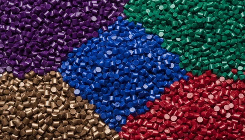
A nossa fábrica em Shanghai opera 47 máquinas de moldagem por injecção de 90T a 1850T, e temos 6 estações de secagem dedicadas. Com mais de 120 trabalhadores de produção e 8 engenheiros de moldes, vimos o que acontece quando a secagem do material é acelerada. Mantemos secadores com ponto de condensação de -40°C para materiais higroscópicos e documentamos os parâmetros de secagem para cada um dos mais de 400 materiais que processamos.
| Material | Drying Temp (°C) | Drying Time (hrs) | Target Moisture (%) |
|---|---|---|---|
| PA6 | 80-100 | 4-6 | <0.02 |
| PC | 120 | 3-4 | <0.02 |
| PEEK | 150-160 | 4-6 | <0.01 |
| ABS | 80-85 | 2-3 | <0.02 |
| POM | 80 | 2-3 | <0.02 |
Non-hygroscopic materials like polypropylene and PE do not require aggressive drying, but surface moisture from condensation should still be removed with a brief 1-2 hour drying cycle at 60-80°C. Skip drying entirely only if the material has been stored in a climate-controlled environment.
A verificação do conteúdo de humidade evita defeitos superficiais e fragilidade estrutural em peças moldadas. Use um analisador de humidade halogenado ou titulação Karl Fischer para confirmar que o conteúdo de humidade da resina permanece abaixo do limite específico do material antes de carregar o alimentador. Objetivos comuns incluem PA6 e PA66 abaixo de 0.2% de humidade, policarbonato e PET a 0.02% ou menos, e PBT abaixo de 0.05%. Na nossa fábrica de Shanghai, verificamos os níveis de humidade em cada lote de produção antes de iniciar o processamento. Material reciclado — mesmo quando armazenado adequadamente em recipientes selados — absorve humidade ambiente mais rápido que resina virgem, tornando a verificação especialmente crítica quando se usa misturas recicladas. Ignorar esta verificação causa marcas de spray, redução de resistência ao impacto e instabilidade dimensional que nenhum ajuste de parâmetro posterior ao moldagem pode corrigir.
Step 3: How Does Clamping and Mold Closing Work?
Fixação aplica força hidráulica ou mecânica medida em toneladas para selar a linha de separação do molde contra pressões de injeção de 18.000–50.000 psi. A regra prática é simples: calcular área projetada da cavidade, multiplicar por pressão máxima pressão de injeção1, depois adicione uma margem de segurança de 10–20%. A fixação correta evita rebarbas, protege a geometria da linha de separação e mantém dimensões repetíveis em toda a produção.
As classificações de tonelagem da máquina definem o máximo clamp force2 disponível. Operar um molde a 60-80% da tonelagem nominal proporciona eficiência energética óptima enquanto mantém margem de segurança adequada para picos de pressão durante as fases de injeção e compactação.
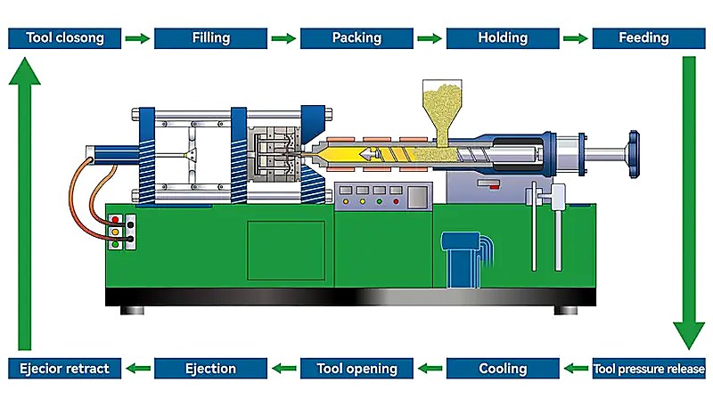
“Clamp force calculation requires 20-30% safety margin.”Verdadeiro
The formula (projected area × injection pressure) gives the theoretical minimum. Adding 20-30% compensates for pressure spikes during filling, thermal expansion of the mold, and variations in material viscosity.
“Higher clamp force always improves part quality.”Falso
Excessive clamp force can crush venting channels, trap air causing burn marks, and accelerate mold wear. The goal is sufficient force to keep the mold closed without creating stress concentrations.
Mold closing speed follows a two-stage profile. Approach stage: rapid closing from 200-300 mm/s until the mold faces are within 5-10mm of contact. Positioning stage: slow closing from 5-10 mm/s for final closure to protect mold surfaces and alignment features. Some modern machines add a third low-pressure protection stage at 1-2 mm/s with 5-10 bar clamping pressure before full clamp engagement. This prevents damage if foreign material or a stuck part remains in the mold cavity.
Teste de montagem
Step 4: How Does Plastic Melting and Injection Work?
A injecção funde pellets de resina num cilindro aquecido através de uma rosca rotativa, depois força o material homogeneizado para dentro da cavidade do molde a 50–200 mm/s. Os grânulos entram no alimentador, movem-se pelo cilindro aquecido e são cortados pela rosca rotativa. As zonas de alimentação, compressão e dosagem transportam, fundem, homogeneizam e dosam o material para que a viscosidade permaneça estável durante o enchimento.
Screw rotation speed affects melt quality and throughput. Too slow: insufficient shear heating creates unmelted pellets. Too fast: excessive shear degrades the polymer and causes discoloration. Most engineering resins perform best at 50-120 RPM, with the speed adjusted based on screw diameter and material viscosity.
In our 20+ years of molding experience since 2005, we have accumulated extensive processing knowledge across 400+ materials. Our Shanghai factory maintains standard screw profiles for each material class and customizes for specialty grades. The screw recovery time—the time to accumulate enough melt for one shot—typically runs 2-4 seconds on our machines, contributing 10-15% to total tempo de ciclo3.
Injection begins when the screw stops rotating and moves forward as a plunger, forcing the accumulated melt through the nozzle, sprue, runner system, and into the cavity. Injection speed controls surface finish and weld line strength. Fast fill reduces temperature loss but can trap air. Slow fill improves venting but may cause premature freeze-off.
Step 5: What Is Packing and Holding Pressure?
The mold is 95-98% full. The cavity is mostly filled but not packed. Packing pressure compensates for volumetric shrinkage as the plastic cools from melt temperature to ejection temperature—typically 10-15% volumetric shrinkage for semi-crystalline materials. Without adequate packing, parts show sink marks, voids, and dimensional variation that pushes them out of tolerance.
“Packing pressure compensates for thermal shrinkage.”Verdadeiro
As plastic cools from injection temperature (200-300°C) to room temperature, density increases and volume decreases by 1-3% depending on material. Packing pressure pushes material into the cavity during this transition to maintain dimensional accuracy.
“Higher packing pressure always eliminates sink marks.”Falso
Excessive packing causes flash at the parting line and ejection problems. Sink marks caused by thick wall sections require design changes like core-outs or rib redesign, not just pressure adjustments.
The critical decision point is gate freeze-off time. The gate must solidify before holding pressure is released, or material flows back out of the cavity. Typical gate freeze times range from 1-3 seconds for edge gates to 0.3-0.8 seconds for sub-gates. Monitor cavity pressure curves—a sharp pressure drop after packing indicates premature gate unfreeze.
Packing pressure profile can be staged rather than constant. Stage 1: High pressure (80-100% of injection) for 20-30% of packing time to drive material into thick sections and corners. Stage 2: Reduced pressure (50-70% of injection) for the remaining time to maintain density without over-packing. This profile reduces sink marks while minimizing flash risk. The transition point is determined by observing the part weight curve and visual inspection of thick sections for sink marks under different pressure levels.
Step 6: How Does Cooling and Solidification Work?
The gate is frozen. The material is packed. The part is dimensionally stable enough to survive ejection but needs to solidify fully before the mold opens. Cooling time dominates cycle time at 60-80% of the total. A 10-second reduction in cooling time on a 25-second cycle is a 40% productivity gain. This is where engineering pays for itself.
O resfriamento convencional usa canais retos perfurados com diâmetro de 8–12 mm, espaçamento de 3–5 vezes o diâmetro, e distância da superfície da peça ao centro do canal de 2–3 diâmetros. Isso funciona para peças com espessura uniforme e geometria simples. Quando tem bossas, nervuras ou espessuras variáveis, o resfriamento uniforme torna-se difícil — secções grossas resfriam mais lentamente, causando retração diferencial, deformação e tensão residual.
ZetarMold has implemented conformal cooling channels on high-volume molds since 2013. By following the mold cavity contour rather than straight drilling, we have reduced cooling time by 20-35% for complex parts. This capability, combined with our in-house mold manufacturing facility, allows us to deliver 100+ molds per month with optimized cooling designs.
| Material | 2mm Wall (s) | 3mm Wall (s) | 4mm Wall (s) |
|---|---|---|---|
| PP | 8-10 | 12-15 | 16-20 |
| ABS | 10-12 | 15-18 | 20-24 |
| PC | 12-15 | 18-22 | 25-30 |
| PA6 | 10-12 | 15-18 | 20-25 |
| PEEK | 15-18 | 22-27 | 30-36 |
Coolant temperature should be 10-20°C below the material’s heat deflection temperature. For PC, set mold temperature at 80-100°C. For PP, 20-40°C works. Higher mold temperatures improve surface finish and crystallinity but extend cycle time. The tradeoff is always cosmetic quality versus throughput.
Optimização de resfriamento pode reduzir tempo de ciclo por 20-35% em moldes existentes sem alterações de hardware. Ajustes de processo: reduzir tempo de compactação ao mínimo que mantém peso da peça, aumentar taxa de fluxo de refrigerante dentro dos limites da bomba, e baixar temperatura do molde ao mínimo que evita deformação. Modificações de molde: adicionar baffles para resfriar núcleos profundos, reposicionar canais mais próximos de secções grossas, e instalar resfriamento conformal para geometrias complexas. ROI é normalmente alcançado dentro de 1000-5000 peças.
Step 7: How Does Mold Opening and Part Ejection Work?
The part is solidified. The cooling time has elapsed. The mold opens. This seems straightforward, but ejection is where 20-30% of injection molding defects occur. Ejection requires overcoming two forces: adhesion of the cooled plastic to the mold steel and mechanical interlocking due to undercuts or insufficient draft. The ejection system must apply enough force to overcome these factors without distorting the part, creating ejector pin marks, or causing part stick-back on the core side.
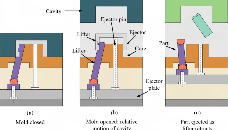
“Ejection force should be 1.5-2 times the projected part area.”Verdadeiro
Para uma área projetada de 50 cm² na superfície do molde, uma força de ejectação de 75-100 N proporciona ejectação fiável enquanto minimiza marcas de pinos. A ejectação excessiva causa marcas de pinos e danos na superfície.
“More ejector pins always improve ejection reliability.”Falso
Excessive pins create surface marks, increase mold cost, and create more failure points. Strategic pin placement at rib intersections and corners is more effective than pin quantity alone.
Ejection system selection depends on part geometry. Straight ejection uses ejector pins for simple geometries. Sleeve ejection handles bosses and cylindrical features. Stripper plate ejection works best for thin-wall cups and caps. For undercuts, you need lifters or angled pins. Choosing the wrong system causes part deformation, sticking, or tooling damage that compounds over thousands of cycles.
Ejector pin placement follows specific guidelines. Place pins in thick sections and rib intersections where ejection resistance is highest. Space pins evenly along the part perimeter to distribute force. Pin diameter should be at least 1.5x the pin length to prevent bending. For polished or textured surfaces, avoid placing pins on visible cosmetic areas.
Mold opening speed affects ejection quality. The opening profile: slow initial opening (5-10 mm/s) for first 10-20mm to allow part separation from core without stress. Rapid opening (100-200 mm/s) for the majority of the stroke to minimize cycle time. Deceleration (20-50 mm/s) for final 50-100mm to avoid slamming the mold open and reducing wear on guide pins and bushings. The deceleration is particularly important for molds with stripper plates or complex lifters that need controlled opening sequences.
Step 8: How Do You Inspect Quality and Monitor the Process?
The part is ejected. It lands in the chute or is robotically removed. Now what? If you assume the process is set and let it run, you will discover defects hours or days later when your customer rejects the shipment. Quality inspection must happen at every shift start, after every material change, and at defined intervals during production. The inspection hierarchy: first article inspection (FAI) on startup, in-process inspection every 50-100 parts, final inspection on each shipment lot.
At ZetarMold, our quality workflow covers IQC (incoming quality control), in-process checks with samples, process inspection, packaging inspection, FQC (final quality control), and OQC (outgoing quality control). We have 10+ QC specialists who verify dimensions, surface quality, and functional requirements on every production run. This 6-step workflow, combined with ISO 9001/13485/14001/45001 certifications, ensures consistent quality across our Shanghai factory operations.
Visual inspection catches 60-70% of defects. Burn marks, flash, short shots, sink marks, and surface blemishes are immediately visible. Train operators to inspect critical cosmetic zones first, then structural features. Use backlit inspection stations for transparent parts and polarized light for birefringence detection in optical components.
| Check | Method | Frequency | Acceptance Criteria |
|---|---|---|---|
| Visual Defects | Lightbox inspection | Every 50 parts | No sink >0.2mm in A-surface |
| Dimensions | CMM/caliper | Every 100 parts | ±0.1mm for ±0.05mm tolerance |
| Peso | Scale | Every 25 parts | ±2% of target weight |
| Fit/Function | Assembly test | Como se calcula a força de fecho para moldação por injeção? | No interference or binding |
| Cosmetic | Golden sample | Every part | Match appearance reference |
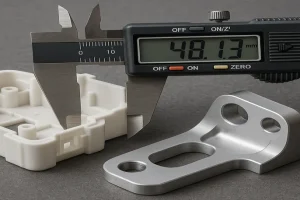
Dimensional inspection verifies parts meet print requirements. Critical dimensions use CMM (coordinate measuring machine) measurement with ±0.01mm accuracy. Standard dimensions get caliper or go/no-go gauge checks. Sample 5 parts per 100-shot cycle for statistical process control, tracking Cp and Cpk values.
Máquinas modernas monitorizam pressão de injeção, pressão de compactação, temperatura de fusão, temperatura do molde, tempo de ciclo e tempo de recuperação do êmbolo em tempo real. Alarmes a ±10–20% dos valores de referência activam paragens automáticas, segregam peças afectadas e alertam operadores — detectando desvio do processo antes que peças fora de especificação acumulem.
What Are Common Injection Molding Issues and How Do You Troubleshoot Them?
Defeitos comuns de moldagem por injeção — marcas de retração, rebarbas e peças incompletas — aparecem mesmo em processos bem ajustados. Aqui estão causas fundamentais e soluções.
Sink marks occur when thick sections cool slower than adjacent thin sections, creating surface depressions. The root cause is differential shrinkage. Troubleshooting path: first check wall thickness ratio—if it exceeds 3:1, redesign is required. If wall thickness is acceptable, increase packing pressure in 10% increments while monitoring for flash. Add baffles or bubblers to cool thick sections faster. Reduce melt temperature 5-10°C to minimize initial shrinkage. In severe cases, add external core-outs or gas-assisted molding to eliminate thick sections entirely.
Flash appears at the parting line, around ejector pins, or in vent gaps when material escapes the cavity under excessive injection or packing pressure. Contributing factors include worn mold surfaces, insufficient clamp force, and high melt temperatures that reduce viscosity. Fix flash by increasing clamp force first, then reducing packing pressure, and finally checking mold surface alignment if the problem persists across multiple cavities.
Short shots occur when the cavity is not completely filled, leaving incomplete parts. Common causes include insufficient injection pressure, blocked vents preventing air escape, low melt temperature increasing viscosity, or inadequate shot size. Diagnose by checking injection pressure curves first—most short shots resolve by raising injection speed or pressure by 10-15%. If venting is the issue, clean or deepen vent channels to 0.01-0.02mm depth.
When Should You Adjust vs. Redesign Your Injection Molding Process?
Mude para redesign quando três ou mais alterações de parâmetros ±20% falham, ou quando causas fundamentais incluem proporções de paredes acima de 3:1 ou ângulos de inclinação inadequados. A regra geral: se ajustou três parâmetros por ±20% e o defeito persiste, o problema é provavelmente relacionado ao design. Continuar a ajustar além deste ponto desperdiça material e tempo de ciclo sem resolver o problema.
“Wall thickness ratio >3:1 requires design modification.”Verdadeiro
When wall thickness exceeds 3:1 ratio, process adjustments cannot eliminate sink marks and warpage. Core-outs, rib redesign, or gas-assisted molding are necessary design solutions.
“All short shots require mold redesign.”Falso
Short shots caused by venting issues, material contamination, or improper drying can be fixed through process changes. Only short shots caused by flow length limitations or trapped air in geometry require mold modification.
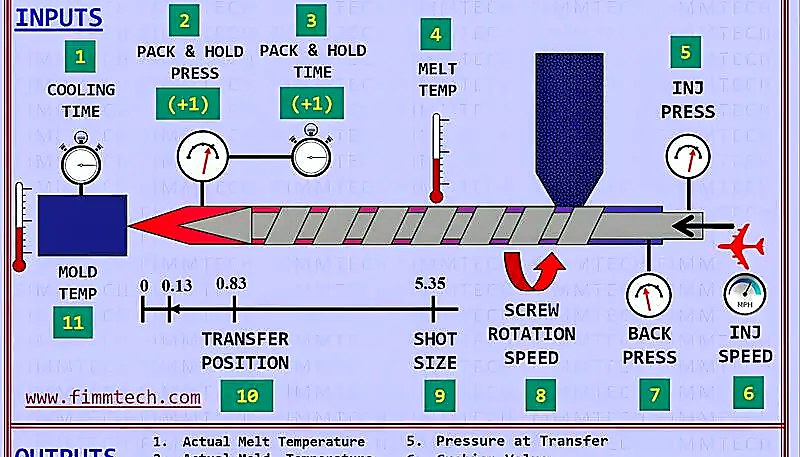
Design issues that resist process adjustment fall into five categories: wall thickness non-uniformity (causes sink and warp), inadequate draft angles (causes sticking), incorrect gate type or location (causes flow lines and weld lines), insufficient coring (wastes material and cycle time), and sharp corners without fillets (creates stress concentrators). Each of these requires a mold modification, not a parameter tweak.
Redesign custa 5.000–15.000 USD para engenharia, modificação e revalidação, mas produzir peças defeituosas a taxas de desperdício de 5–15% numa produção de 100.000 peças custa muito mais.
How Do You Optimize Injection Molding for Production Efficiency?
Priorizar o tempo de refrigeração — domina 60–80% de cada ciclo — através de canais conformais e fluxo turbulento, depois minimizar os tempos de compactação e ejectação. O tempo de ciclo é a soma do tempo de injecção (5–10%), tempo de compactação e retenção (10–20%), tempo de refrigeração (60–80%), tempo de abertura e fecho do molde (5–10%) e tempo de ejectação (2–5%). A refrigeração é o factor dominante, portanto a optimização deve focar-se primeiro aqui, depois passar pelos outros componentes.
ZetarMold opera 47 máquinas de moldagem por injeção de 90T a 1850T, e optimizamos o resfriamento em mais de 100 moldes só no último ano. Implementando resfriamento conformal, optimizando fluxo de refrigerante e redesignando entrada, reduzimos tempos de ciclo por 15-30% em múltiplas linhas de produção. Estas melhorias, combinadas com nossa experiência de mais de 20 anos desde 2005, permitem-nos oferecer preços competitivos mantendo qualidade.
Cooling optimization targets three areas: channel placement, coolant parameters, and mold material selection. Conformal cooling channels follow the part contour, reducing distance to the cavity surface from 15-25mm (drilled) to 3-8mm (conformal). Coolant flow rate must maintain turbulent flow (Reynolds number above 5,000) for effective heat transfer. Mold materials with higher thermal conductivity like beryllium copper inserts in hot spots can cut local cooling time by 30-40%.
Injection optimization focuses on fill time and melt quality. Fill time optimization: reduce injection time until you see burn marks (too fast) or short shots (too slow), then back off 10%. Velocity-to-pressure switchover point should trigger at 95-98% fill to avoid overshooting. Melt temperature profiling across barrel zones prevents degradation while ensuring complete melting.
| Componente | Typical % of Cycle | Optimization Potential | ROI Timeline |
|---|---|---|---|
| Arrefecimento | 60-80% | 15-30% | 500-2000 parts |
| Packing/Holding | 10-20% | 10-20% | Immediate |
| Mold Open/Close | 5-10% | 5-15% | Immediate |
| Injeção | 5-10% | 5-10% | 100-500 parts |
| Ejeção | 2-5% | 5-10% | 1000-5000 parts |
O ROI depende do valor e volume da peça. Retorno abaixo de 1.000 peças deve ser implementado imediatamente; 1.000–5.000 peças precisa de avaliação; acima de 5.000 peças requer justificação estratégica.
Questões Frequentemente Perguntadas sobre o Processo de Moldagem por Injeção
Perguntas mais frequentes
What are the 7 steps of injection molding?
The seven steps of injection molding are: (1) clamping and mold closing, where the machine secures the two mold halves together under high pressure; (2) plastic melting and injection, where heated pellets become molten and are forced into the cavity; (3) packing and holding, where additional material compensates for shrinkage; (4) cooling and solidification, where the part hardens inside the mold; (5) mold opening and part ejection, where the finished part is removed; (6) quality inspection, which covers visual, dimensional, and functional checks; and (7) process monitoring and adjustment, ensuring consistent output throughout production runs.
How long does an injection molding cycle take?
Cycle time ranges from as short as 5 seconds for small thin-wall parts to over 120 seconds for large, thick-wall components. For a typical engineering plastic part with 3mm wall thickness, expect 15-25 seconds per cycle. Cooling dominates the timeline, accounting for 60-80% of total cycle time, while injection fills the cavity in just 0.5-2 seconds. Reducing cooling time through conformal channels or optimized coolant flow is the single most effective way to increase throughput, often cutting cycle time by 20-35% on existing molds.
What is the difference between injection and packing?
Injection is the high-pressure fill phase where molten plastic is forced into the mold cavity at speeds designed to fill 95-98% of the volume, typically completing in 0.5-2 seconds. Packing (or holding) follows immediately at lower pressure, pushing additional material into the cavity to compensate for thermal shrinkage as the plastic cools and contracts. Packing continues until the gate freezes off, usually 2-6 seconds. Think of injection as getting the material into the mold, and packing as keeping it dimensionally accurate as it solidifies.
Why do I need to dry plastic before injection molding?
Hygroscopic materials such as PA6, PC, PET, and PEEK absorb moisture from ambient air over time. During injection molding, this trapped moisture vaporizes instantly at melt temperatures (often above 250°C), causing visible bubbles (splay marks), surface streaks, reduced mechanical strength, and dimensional instability in the finished part. Proper drying at material-specific temperatures (80-160°C) for 3-6 hours reduces moisture content below the critical 0.02% threshold required for defect-free molding. Skipping the drying step remains one of the most common and costly causes of rejected parts in production.
What temperature is used for injection molding?
Injection molding temperatures vary significantly by material type. Polypropylene processes at 180-220°C, ABS at 210-250°C, polycarbonate at 280-320°C, and high-performance PEEK requires 380-420°C. The barrel maintains a temperature gradient from the feed zone (coolest) through compression to the metering zone (hottest), typically with a 20-40°C rise. Mold temperature also plays a critical role: colder molds speed up cycle time but can increase residual stress, while heated molds (60-150°C depending on resin) improve surface finish, crystallinity, and dimensional stability for engineering-grade materials.
How much pressure is needed for injection molding?
Injection pressure typically ranges from 18,000 to 25,000 psi for standard engineering thermoplastics. High-viscosity or glass-filled materials like PEEK or PA66-GF30 can require up to 35,000-50,000 psi. Packing pressure runs at 50-80% of injection pressure. To determine required clamp force, multiply the projected part area (in square inches) by injection pressure, then add a 20-30% safety margin. For example, a 10 square inch part at 18,000 psi needs roughly 90 tons of clamp force, so a 110-115 ton machine provides adequate headroom.
What causes sink marks in injection molding?
Sink marks form when thick wall sections cool more slowly than adjacent thin sections, creating differential shrinkage that physically pulls the surface material inward. The primary causes include wall thickness ratios exceeding 3:1, insufficient packing pressure or hold time, and inadequate cooling channel placement near heavy cross-sections. Practical fixes include coring out thick sections during the DFM stage, increasing packing pressure and extending hold time until gate freeze, and redesigning cooling channels to target thick areas. Process adjustments can resolve mild cases, but severe recurring sinks usually require a mold modification.
How do you calculate clamp force for injection molding?
Domine o processo de moldagem por injeção passo a passo: desde a revisão de DFM, passando pelo fecho, injeção, enchimento, arrefecimento e ejeção, até à inspeção de qualidade.
-
pressão de injeção: Pressão de injeção refere-se à pressão hidráulica aplicada ao êmbolo para forçar plástico fundido na cavidade do molde, tipicamente variando de 35.000 a 50.000 psi. ↩
-
clamp force: Força de fixação é a força hidráulica ou mecânica que mantém o molde fechado durante injeção, medida em toneladas, com 90T a 1850T sendo intervalos comuns. ↩
-
tempo de ciclo: O tempo de ciclo é a duração total necessária para completar um ciclo de moldagem por injecção, medido em segundos, desde o fecho do molde até ao início do próximo ciclo. ↩




 EN
EN  ES
ES  FR
FR  DE
DE  PT
PT  AR
AR  RU
RU  JA
JA  KO
KO  IT
IT  NL
NL  TR
TR  PL
PL 