 Overslaan naar inhoud

Je hebt net je eerste productiemonsters teruggekregen en de onderdelen blijven in de mal steken. Uitstoters laten sporen na. Sommige onderdelen hebben zelfs sleepkrassen langs de zijkant. Je gereedschapsmaker zegt dat je meer ontluchting nodig hebt. Je had om nul ontluchting gevraagd omdat de CAD er schoon uitzag. Nu heb je een $12.000 mal die moet worden herwerkt. Het goede nieuws: dit is een van de gemakkelijkste problemen om te voorkomen als je ontluchtingshoeken begrijpt voordat het gereedschap begint.
Dit artikel behandelt wat trekhoek1 is, waarom het belangrijk is, standaardwaarden per materiaal en textuur, en de fouten die ik heb gezien kosten echt geld op echte productieruns.
- Standaard ontluchting is 1 tot 2 graden per zijde voor de meeste gepolijste oppervlakken.
- Getextureerde oppervlakken hebben 1 tot 1,5 graden extra ontluchting per textuurklasse nodig.
- Nul ontwerp is mogelijk maar riskant en bijna nooit de moeite waard in productie.
- Ontluchting moet worden toegepast voordat het gereedschap begint — herwerking is duur.
- Krimp, materiaal en wanddikte beïnvloeden allemaal de minimale benodigde ontluchting.
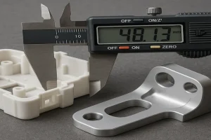
Micro-gevormde Onderdelen Close-up
A spuitgieten Ontluchtingshoek is de opzettelijke tapsheid die in elk verticaal oppervlak van een malholte is ingebouwd. Zie het als de lichte helling die je aan een wand toevoegt, zodat het onderdeel vrij kan glijden zodra het afkoelt en op de kern krimpt. Zonder dit grijpt het onderdeel het staal als een vacuümzegel en wordt uitwerpen een gevecht tussen je uitstoters en het maloppervlak.
De ontluchtingshoek wordt gemeten in graden vanaf de verticale as van de malopeningsrichting. Een ontluchting van 1 graad betekent dat de wand ongeveer 0,0175 mm per mm diepte naar buiten helt. Op een zak van 50 mm diep geeft dat ongeveer 0,87 mm speling per zijde aan de bovenkant. Het klinkt klein, maar het is het verschil tussen schoon uitwerpen en een vastzittend onderdeel.
Elke verticale oppervlakte in uw onderdeel heeft ontwerp nodig. Dat omvat buitenmuren, binnenribben, nokken, zakken en zelfs doorlopende gaten. Als een oppervlak parallel loopt aan de richting van de matrijsopening en geen tapsheid heeft, zal het onderdeel tijdens het uitwerpen slepen, wat krassen, groeven of vervorming veroorzaakt.
Waarom is Ontluchtingshoek Belangrijk voor Onderdeelkwaliteit?
Dit gedeelte gaat over waarom ontwerphoek van belang is voor de onderdeelkwaliteit en de impact op kosten, kwaliteit, timing of inkooprisico. Ontwerphoek beïnvloedt direct vier zaken: onderdeelcosmetica, dimensionale nauwkeurigheid, gereedschapslevensduur en cyclusduur. Wanneer een onderdeel in de matrijs blijft steken, de spuitgietvorm uitwerpsysteem2 moet harder werken. Uitstoters laten getuigenissporen na. Het onderdeeloppervlak krijgt sleepstrepen. In het ergste geval scheurt of vervormt het onderdeel voordat het loskomt.
Onvoldoende ontluchting versnelt ook de slijtage van de mal. Elke cyclus schraapt het onderdeel tegen de holtewand tijdens het uitwerpen. Over 100.000 cycli polijst en beschadigt die constante wrijving het stalen oppervlak. Een mal die 500.000 cycli zou moeten meegaan, heeft mogelijk al na 200.000 cyclis polijsten of herwerking nodig.
Aan de productiekant vertragen onderdelen die moeilijk uit te werpen zijn de cyclus. Als je operator het onderdeel handmatig moet loskloppen, of als de robot moeite heeft het vast te grijpen, verlies je seconden per cyclus. Op grote schaal loopt dat op tot echt geld. Een vertraging van 3 seconden op een cyclus van 30 seconden is een capaciteitsverlies van 10 procent.
“A 1-degree draft angle can reduce ejection force by up to 50% compared to zero draft.”Echt
De coniciteit doorbreekt het vacuümeffect tussen het krimpende plastic en de matrijs kern. Zelfs een kleine hoek verlaagt de wrijvingscoëfficiënt tijdens het uitwerpen aanzienlijk, waardoor de benodigde kracht van het uitwerpsysteem vermindert.
“If the mold has enough ejector pins, you do not need draft angle.”Vals
Meer uitwerpstiften verdelen de kracht beter, maar ze kunnen de fundamentele wrijving tussen een parallelle wand en het krimpende plastic niet overwinnen. Zonder ontwerp concentreren stiften de kracht alleen op kleinere oppervlakken, wat het risico op stiftmarkeringen en onderdeelvervorming vergroot.
Wat zijn de standaard ontwerphoekwaarden?
Er is geen enkele juiste ontwerphoek — het hangt af van materiaal, oppervlakteafwerking, diepte en tolerantie-eisen. Maar hier zijn de waarden die in de praktijk werken bij duizenden productiematrijzen.
| Afwerking oppervlak | Minimale ontwerp | Aanbevolen ontluchting | Opmerkingen |
|---|---|---|---|
| Gepolijst (SPI A-1 tot A-3) | 0.5° | 1° | Glad oppervlak laat gemakkelijk los |
| Standaard (SPI B-1 tot B-3) | 1° | 1.5° | Lichte bewerkingssporen |
| Fijne textuur (VDI 12-24) | 1° | 1,5° tot 2° | Voeg 1° per textuurdiepteklasse toe |
| Medium Textuur (VDI 27-33) | 1.5° | 2° tot 3° | Textuur vergrendelt op het onderdeeloppervlak |
| Zware textuur (VDI 36-45) | 2° | 3° tot 5° | Diepe korrel werkt als micro-ondesnijdingen |
| Gepolijst, nul ontwerp | 0° | Not recommended | Alleen voor ondiepe kenmerken onder 10 mm |
De vuistregel die ik gebruik: begin met 1 graad per zijde voor gepolijste oppervlakken, voeg 1 graad toe voor elke textuurklasse toename en ga nooit onder 0,5 graden op iets dieper dan 10 mm. Als je klant terugduwt op ontluchting vanwege dimensionale beperkingen, laat ze dan de berekening zien van wat herwerking kost versus een tapsheid van 0,5 graden.
Voor interne kenmerken zoals ribben en penningen is de ontwerpsituatie kritischer. Het plastic krimpt tijdens het koelen op de kern, wat een stevige grip creëert. Ribben moeten minimaal 0,5 graden per zijde hebben, maar 1 graad is veiliger. Penningen hebben minstens 0,5 graden nodig aan de buitenkant, en het binnenste gat moet ook ontworpen worden als het wordt gevormd door een kernpen.
Hoe Beïnvloedt Materiaalkrimp de Ontluchtingsvereisten?
krimp3 is de reden waarom ontwerp überhaupt bestaat. Wanneer plastic in de matrijs afkoelt, krimpt het. Als het onderdeel de vorm heeft van een kopje of doos, trekt die krimp de wanden strak tegen de matrijskern aan. Hoe hoger de krimpsnelheid, hoe strakker de grip, en hoe meer ontwerp je nodig hebt.
| Materiaal | Krimppercentage | Min. Trekkracht (Gepolijst) | Minimale ontwerp (Getextureerd) |
|---|---|---|---|
| ABS | 0.4–0.7% | 0.5° | 1.5° |
| Polycarbonaat (PC) | 0.5–0.7% | 0.5° | 1.5° |
| Nylon 6 (PA6) | 0,5–1,5% | 1° | 2° |
| Nylon 66 (PA66) | 0,8–2,0% | 1° | 2,5° |
| Glass-Filled Nylon | 0.2–0.8% | 0.5° | 1.5° |
| PP (polypropyleen) | 1.0–2.5% | 1° | 2,5° |
| PE (polyethyleen) | 1.5–3.0% | 1.5° | 3° |
| POM (Acetal) | 1.5–2.5% | 1° | 2,5° |
| PBT | 0,8–2,0% | 1° | 2° |
Crystalline materials like nylon, PP, and POM shrink more than amorphous materials like ABS and PC. That means they grip the core harder and need more draft. Glass-filled nylon is an exception: the glass fibers reduce shrinkage, so it actually needs less draft than unfilled nylon, even though the fibers make the material more abrasive on the mold.
We once ran a PP housing project where the customer insisted on 0.5-degree draft with a medium texture. The parts stuck on every other cycle. We ended up re-cutting the core to add 1.5 degrees more draft — three weeks of lost production. PP with 2.5 percent shrinkage on a textured surface was never going to work at 0.5 degrees.
What Happens When Draft Is Insufficient?
The symptoms show up immediately on the production floor. Here is what you will see, in order of severity:
First, drag marks. The part surface gets parallel scratches along the ejection direction. On polished parts, this is immediately visible and rejects the part cosmetically. On textured parts, the texture gets polished off in streaks, creating an uneven finish that no amount of post-processing can fix.
Second, ejector pin marks. When the part resists ejection, the pins concentrate force on small areas. You get white stress marks on the inside, visible pin push marks, or even pin-through holes if the wall is thin. In our shop, we consider any pin mark deeper than 0.1 mm a reject for visible surfaces.
Third, part distortion. If the part does release but with high ejection force, it can warp, bow, or crack. Thin-walled parts are especially vulnerable. The force needed to push a zero-draft part out of a deep cavity can exceed the structural strength of the wall, causing permanent deformation.
Fourth, mold damage. Over time, the constant high-force ejection wears ejector pin holes, scores cavity surfaces, and can crack cores. A mold running zero-draft deep pockets might need pin replacement every 50,000 cycles instead of every 200,000. That is four times the maintenance cost.
“Adding 1 degree of draft to a textured surface can eliminate ejection drag marks completely.”Echt
The additional taper creates clearance between the shrinking plastic and the textured steel surface. This clearance breaks the mechanical interlock between the texture pattern and the solidified part surface, allowing clean release.
“Draft angle only matters for cosmetic parts — structural parts do not need it.”Vals
Draft is a mechanical requirement, not just a cosmetic one. Structural parts face the same shrinkage and friction forces during ejection. In fact, structural parts with tight tolerances are even more sensitive to ejection-induced warpage caused by insufficient draft.
How Do Texture and Surface Finish Change Draft Requirements?
This is where most draft problems originate. A polished mold surface is essentially smooth — the part slides out with minimal friction. But a textured surface has microscopic peaks and valleys that act like tiny undercuts. As the plastic shrinks, it wraps around those peaks, creating a mechanical lock that resists ejection.
The industry standard rule: add 1 degree of draft per 0.01 mm of texture depth. Most texture suppliers rate their patterns on a scale from fine to coarse. A fine sandblast texture might be 0.01 mm deep and only need 1 extra degree. A deep leather grain could be 0.05 mm deep and need 5 extra degrees on top of the base draft.
If you are specifying a texture on your part, always tell your toolmaker before the mold is cut. Changing the surface finish after tooling often means re-cutting the cavity to add draft, which is expensive and can affect the part dimensions. We had a case where a customer added a VDI-33 texture to a mold that was designed for a polished finish with 1 degree draft. The mold had to be pulled, the cavity re-cut to 3.5 degrees, and re-polished. Six weeks of downtime.
How to Calculate Draft Angle for Your Part?
The basic calculation is straightforward. Draft clearance equals the tangent of the draft angle multiplied by the depth of the feature:
Clearance per side = tan(draft angle) x depth
For example, a 1-degree draft on a 50 mm deep wall gives: tan(1°) x 50 = 0.0175 x 50 = 0.87 mm clearance per side. At 2 degrees, it is 1.75 mm per side. At 3 degrees, 2.62 mm per side.
The practical question is not the math — it is whether your part can tolerate that much size variation from bottom to top. For most enclosures and housings, 1 to 2 mm of taper across a 50 mm wall is invisible to the end user. But for precision components like gears, bearing seats, or mating interfaces, you may need to hold tighter draft or use alternative ejection strategies.
| Depth (mm) | 0.5° Draft | 1° Draft | 1.5° Draft | 2° Draft | 3° Draft |
|---|---|---|---|---|---|
| 10 | 0.09 | 0.17 | 0.26 | 0.35 | 0.52 |
| 25 | 0.22 | 0.44 | 0.65 | 0.87 | 1.31 |
| 50 | 0.44 | 0.87 | 1.31 | 1.75 | 2.62 |
| 75 | 0.65 | 1.31 | 1.96 | 2.62 | 3.93 |
| 100 | 0.87 | 1.75 | 2.62 | 3.49 | 5.24 |
Notice that even a small depth of 10 mm with 0.5 degrees only gives you 0.09 mm of clearance. That is barely enough to overcome surface friction, especially if there is any texture. This is why most toolmakers push back on anything below 1 degree — the margin for error is too thin.
What Are Common Draft Angle Mistakes?
Common draft angle mistakes are the main categories or options explained in this section. After 20 years of building molds, the same mistakes come up over and over. Here are the ones that cost the most money:
Mistake 1: Applying draft only to outside walls. Inside features like ribs, bosses, and gussets are often forgotten. These surfaces shrink onto the core just like outside walls, but they are harder to eject because the ejector pins cannot reach them directly. Every rib needs at least 0.5 degrees per side. Every boss needs at least 0.5 degrees outside.
Mistake 2: Opposing draft directions. If you draft the cavity side one way and the core side the other, the part gets thicker at one end and thinner at the other. This creates uneven wall thickness that causes warpage and sink marks. All draft on a given feature should converge toward the parting line so wall thickness stays consistent.
Mistake 3: Ignoring draft on shut-off surfaces. When a through-hole or window is formed by both halves of the mold meeting, the shut-off surface needs draft too. Without it, the steel-on-steel contact area acts as a brake during mold opening. We have seen molds where the press had to be cranked up 20 percent in tonnage just to overcome shut-off friction from zero-draft horizontal surfaces.
Mistake 4: Not accounting for post-mold texture. Some customers plan to add texture after molding through painting or pad printing. If the draft was calculated for a polished surface and the post-process adds thickness, the effective clearance drops. Always design for the final surface condition, not the as-molded condition.
Mistake 5: Zero draft on deep pockets. This is the single most expensive mistake. Deep pockets with zero draft almost always cause ejection problems. If the design absolutely cannot have draft, plan for a split core or collapsible core from the start. It costs more up front but avoids the rework bill later.
How to Handle Draft on Complex Part Geometries?
Not every part is a simple box with straight walls. Real production parts have undercuts, side features, angled holes, and asymmetric geometry. Here is how to handle draft in the common complex scenarios.
Angled surfaces. If a wall is already angled more than the required draft, you do not need to add more. A wall that leans 5 degrees from vertical already has 5 degrees of draft. Only add draft if the surface is closer to vertical than the minimum requirement.
Ribs and gussets. Draft ribs from the base to the tip. The base is the thickest part and where the rib meets the wall. The tip is the thinnest. A typical rib has 0.5 to 1 degree per side, which naturally makes the tip thinner. Make sure the tip does not get thinner than 0.5 mm, or it will not fill properly.
Threads and undercuts. External threads formed in the cavity need draft on the thread flanks, which changes the thread profile. This is why most production threaded parts use threaded inserts or unscrewing cores instead of direct molded threads. If you must mold threads, work with your toolmaker to validate the thread gauge will still fit after draft is applied.
Louver and vent patterns. These features have thin vanes that need draft on both sides. Because they are thin and deep, they are ejection trouble spots. Use a minimum of 1 degree per side, and specify polished surfaces on the mold for these features.
What Draft Angle Should You Specify in Your Mold Design?
Here is the decision framework I use when reviewing a mold design for draft adequacy. It works for 95 percent of production parts:
Step 1: Identify every surface that is parallel to the mold opening direction. Mark them in your CAD system with a color code. Red for zero draft, yellow for marginal draft (0.5 degrees or less), green for adequate draft (1 degree or more).
Step 2: For each red or yellow surface, determine the surface finish. Polished surfaces can get away with less draft. Textured surfaces need more. Check with your texture supplier for their recommended draft per pattern.
Step 3: Check the material shrinkage. Cross-reference the shrinkage rate with the draft table above. Higher shrinkage means you need more draft to overcome the grip on the core.
Step 4: Verify wall thickness is consistent from bottom to top. If adding draft makes the wall too thick or too thin at one end, adjust the part geometry to compensate. Moving the parting line or changing the wall profile are usually the easiest fixes.
Step 5: Review with your toolmaker before cutting steel. A 30-minute design review can save weeks of rework. Your toolmaker knows which features are ejection trouble spots from experience.
In our factory, our engineers review every mold design for draft adequacy before machining begins. Our team checks ribs, bosses, textured sidewalls, and ejection direction against the DFM record, so draft-related rework stays below 1% across 100+ mold sets delivered per month from our Shanghai factory.
That is why our team treats draft angle as a production-risk review item, not a cosmetic CAD preference. Our engineers mark any zero-draft or marginal-draft surface before steel cutting, then confirm the customer can accept the small taper before machining starts.
Veelgestelde vragen
What is the minimum draft angle for injection molding?
The minimum draft angle is 0.5 degrees per side for polished surfaces on low-shrinkage materials like ABS or PC. For textured surfaces or high-shrinkage materials like PP or nylon, the practical minimum is 1.5 to 2 degrees. Anything less than 0.5 degrees is extremely risky and should only be attempted on shallow features under 10 mm depth with polished mold surfaces and robust ejection systems. In production environments, most experienced toolmakers will not recommend going below 1 degree on any surface deeper than 15 mm regardless of finish or material.
Can you injection mold without draft angle?
Technically yes, but it is almost never recommended for production runs. Zero draft is possible on very shallow features under 10 mm with polished mold surfaces and low-shrinkage materials. For anything deeper, zero draft will cause ejection drag marks, pin push, part warpage, and accelerated mold wear that dramatically shortens tool life. If your design absolutely requires zero draft, plan for alternative ejection methods like air blasts, stripper plates, or collapsible cores from the start. These alternatives add cost and complexity but are necessary to avoid production problems.
How much draft do you need for textured injection molded parts?
The standard rule is 1 degree of draft per 0.01 mm of texture depth. A fine texture rated VDI 12 to 24 typically needs 1 to 1.5 degrees of additional draft on top of the base 1 degree. Medium textures need 2 to 3 degrees total per side. Heavy textures like leather grain may require 3 to 5 degrees total per side. Always confirm with your texture supplier, as their specific pattern depth determines the exact requirement. Failing to add sufficient draft for texture is one of the most common and expensive mold design mistakes in the industry.
Does draft angle affect part tolerances?
Yes, draft angle changes the part dimensions from bottom to top of the drafted surface, and this effect must be accounted for in tolerance specifications. On a 50 mm deep wall with 1 degree of draft, the top of the wall is approximately 0.87 mm wider per side than the bottom. For most cosmetic parts, this taper is invisible to the user. For precision parts with mating surfaces, you need to control which end of the draft holds the critical dimension and clearly communicate this to your toolmaker in the tolerance specification to avoid assembly issues.
What is the difference between draft angle and taper?
In injection molding context, draft angle and taper refer to the same geometric feature, which is defined as the intentional lean applied to vertical surfaces for part ejection. Draft angle is the standard term used in mold design and is measured in degrees from the mold opening direction. Taper is sometimes used in machining contexts and may be expressed as a ratio such as 1 to 50. For practical purposes in mold design discussions, they are interchangeable, but it is always best practice to specify values in degrees to avoid confusion between design and manufacturing teams.
How do you add draft to ribs and bosses?
Ribs should be drafted from the base where they meet the wall out to the tip. Use 0.5 to 1 degree per side, and ensure the tip does not get thinner than 0.5 mm to avoid fill problems during molding. Bosses need draft on the outside surface at a minimum of 0.5 degrees, and the inside hole also needs draft if it is formed by a core pin. For bosses taller than 15 mm, consider increasing draft to 1 degree per side to ensure reliable ejection. Always verify that rib and boss draft directions are consistent with the main wall draft to maintain uniform wall thickness throughout the part.
What draft angle does glass-filled nylon need?
Glass-filled nylon typically needs 0.5 to 1 degree of draft per side for polished surfaces, and 1.5 to 2 degrees for textured surfaces. The glass fibers reduce shrinkage compared to unfilled nylon, which actually lowers the draft requirement on the shrinkage side. However, glass-filled nylon is abrasive on mold surfaces, so adequate draft helps reduce friction and extend mold life significantly. The fibers do not change the fundamental draft calculation, but the reduced shrinkage means the part grips the core less tightly, giving you slightly more margin on minimum draft values than unfilled nylon would allow.
–text How Should You Apply Draft Angle Knowledge to Your Next Project?
Draft angle is one of those fundamentals that separates a smooth production run from an expensive rework project. The rules are simple: 1 degree per side minimum for polished surfaces, add 1 degree per texture grade, account for material shrinkage, and never cut steel without reviewing every vertical surface for adequate draft.
If you take one thing from this article, let it be this: add draft early, add it generously, and review it with your toolmaker before the mold is cut. It also helps to map draft decisions against the stappen van spuitgieten, because draft affects filling, cooling, ejection, and inspection rather than only CAD appearance. The cost of an extra degree of draft at the design stage is zero. The cost of adding it after the mold is built is measured in weeks and thousands of dollars.
Need a mold built right the first time? Use our supplier sourcing guide to check whether a mold maker can review draft angles, DFM risks, and ejection evidence before you commit to tooling.
-
draft angle: A draft angle is the taper applied to the vertical surfaces of a mold cavity, measured in degrees, that allows the molded part to be ejected without friction or damage. ↩
-
ejection system: An ejection system is defined as the mechanical assembly inside a mold that pushes the cooled part out of the cavity, typically consisting of ejector pins, sleeves, or stripper plates. ↩
-
shrinkage: Shrinkage refers to the dimensional reduction of a plastic part as it cools from melt temperature to room temperature, typically expressed as a percentage of the original mold dimension. ↩





 EN
EN  ES
ES  FR
FR  DE
DE  PT
PT  AR
AR  RU
RU  JA
JA  KO
KO  IT
IT  NL
NL  TR
TR  PL
PL 