 콘텐츠로 건너뛰기

벽 두께[1] is arguably the single most important design parameter in injection molding. Get it right, and your part molds cleanly, functions reliably, and costs less. Get it wrong, and you’re dealing with sink marks, warpage, voids, and cycle times that eat your margin.
핵심 요약:
- Keep nominal wall thickness between 1.5–3.0 mm for most engineering thermoplastics.
- Maintain wall variation within ±25% of the nominal value throughout the part.
- Use 3:1 taper ratio for transitions between different wall thicknesses.
- Keep rib base thickness at 50–60% of nominal wall to avoid sink marks.
- Cooling time scales with the square of wall thickness — thin-wall design has high ROI.
This guide covers everything engineers need to know about 사출 성형 wall thickness: how to choose the right value, what happens when walls aren’t uniform, material-specific guidelines, and the most common mistakes from thousands of DFM reviews.
What Is Wall Thickness in Injection Molding?
Wall thickness is the distance between the outer and inner surface of a molded part at any cross-section. It determines how plastic flows through the injection mold cavity, how quickly the part cools, and whether final dimensions hold to specification.
“Wall thickness variation should stay within ±25% of the nominal value.”True
The industry guideline is ±25% variation. Exceeding this without gradual transitions causes differential shrinkage, warpage, and dimensional instability.
“A rib with base thickness equal to 80% of the nominal wall will not cause sink marks.”False
Ribs thicker than 50–60% of nominal wall almost always produce visible sink marks because the rib creates a localized hot spot that cools much slower than the surrounding wall.
Thinner walls save material and reduce cycle time, but increase injection pressure requirements and risk short shots. Thicker walls flow more easily but cool slowly, extending cycle time and increasing the risk of voids and sink marks. The sweet spot for most engineering thermoplastics is 1.5–3.0 mm. Always verify your chosen thickness against the material supplier’s data sheet and flow simulation results before finalizing the design.
Why Is Uniform Wall Thickness So Important?
Non-uniform wall thickness is the root cause of more molding defects than any other single design error. When walls vary significantly, thick sections cool and shrink at a different rate than thin sections. This differential shrinkage사출 성형[2] creates internal stresses that manifest as warpage, sink marks, and dimensional instability.
“Multiple thin ribs are generally better than one tall, thick rib for stiffness.”True
Multiple thin ribs distribute stress evenly, cool faster, and produce minimal sink marks compared to a single thick rib creating a localized thermal mass.
“A sharp 90° transition from 3 mm to 1.5 mm wall is acceptable if the thinner section is short.”False
Abrupt transitions create stress concentrations regardless of length. They cause flow hesitation, increased residual stress, and visible surface defects. Always use the 3:1 taper ratio.
The guideline is straightforward: maintain wall thickness within ±25% of the nominal value throughout the entire part. If your nominal wall is 2.5 mm, every section should fall between 1.9 mm and 3.1 mm.
What Is the Recommended Wall Thickness by Material?
Different materials have different flow characteristics and shrinkage rates. Here’s a practical reference table based on extensive production data.
| 재료 | Min Wall (mm) | Ideal Range (mm) | Max Practical (mm) |
|---|---|---|---|
| ABS | 0.8 | 1.5–3.0 | 4.5 |
| PC(폴리카보네이트) | 0.8 | 1.5–3.0 | 4.5 |
| PP(폴리프로필렌) | 0.6 | 1.2–2.5 | 5.0 |
| PA (Nylon 6/66) | 0.6 | 1.0–3.0 | 4.0 |
| POM (Acetal) | 0.8 | 1.0–3.0 | 4.0 |
| PMMA (Acrylic) | 0.8 | 1.5–3.5 | 5.0 |
| PBT | 0.8 | 1.0–3.0 | 4.0 |
| PE(폴리에틸렌) | 0.6 | 1.0–2.5 | 5.0 |
| PS(폴리스티렌) | 0.8 | 1.0–3.0 | 4.5 |
| TPE/TPU | 0.5 | 1.0–3.0 | 5.0 |
The minimum wall values represent what’s technically possible with optimized processing, not what’s recommended for production. For reliable manufacturing, stay within the ideal range.
How Do You Transition Between Different Wall Thicknesses?
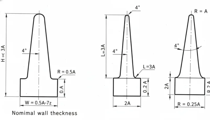
Sometimes wall thickness variation is unavoidable. When it happens, the transition between thick and thin sections is critical. The standard guideline is a 3:1 taper ratio: for every 1 mm of thickness change, provide at least 3 mm of gradual transition.
Abrupt thickness changes cause flow hesitation, stress concentrations, and visible sink marks on the opposite surface. In severe cases, parts crack at thickness transitions during assembly because residual stress exceeds the material’s yield strength.
What Happens When Walls Are Too Thick?
Thick walls create three problems: excessive cycle time, internal voids, and sink marks.
Cycle Time Penalty
Cooling time scales approximately with the square of wall thickness. A part with 2 mm walls might cool in 15 seconds; the same geometry with 4 mm walls could take 50–60 seconds. Across a production run of 100,000 parts, that’s thousands of additional machine hours.
“Cooling time scales with the square of wall thickness — doubling wall quadruples cooling time.”True
This non-linear relationship is why thin-wall design has such high ROI. Reducing wall from 4mm to 2mm can cut cooling time by 75%.
“Reducing wall thickness always improves part quality and production efficiency.”False
While thin walls reduce material usage and cycle time, walls that are too thin cause short shots, increase injection pressure requirements, and compromise structural integrity. The optimal thickness balances flow, strength, and cost.
내부 공동
두꺼운 부분이 냉각될 때 외피가 먼저 고화되고 내부는 여전히 용융 상태입니다. 내부가 수축하면서 고화된 외피에서 떨어져 내부 공동을 생성하여 구조적 강도를 감소시키며 — 특히 하중을 지탱하는 응용 분야에서 문제가 됩니다.
싱크 마크
싱크 마크는 동일한 현상의 표면 표현입니다. 두꺼운 부분의 재료가 수축하면 표면을 안쪽으로 당겨 특히 광택 표면에서 눈에 띄는 움푹 패인 곳을 만듭니다. 리브-벽 비율은 싱크 심도를 직접 제어합니다: 기준 벽의 50–60%보다 더 두꺼운 리브는 거의 항상 눈에 보이는 싱크 마크를 생성합니다.
What Happens When Walls Are Too Thin?
얇은 벽은 그 자체로 위험을 가집니다. 가장 즉각적인 것은 불완전 충전입니다 — 플라스틱 용융물이 캐비티를 완전히 채우기 전에 고화됩니다. 폴리카보네이트 같은 고점도 재료와 유동 경로가 길어 용융 점도가 이미 높은 경우 특히 문제가 됩니다.
얇은 벽은 또한 사출 압력 요구량을 증가시킵니다. 요구 압력이 장비 능력을 초과하면 불완전 충전과 높은 잔류 응력이 발생합니다.
구조적 무결성은 또 다른 고려사항입니다 — 낙하 시험을 거치는 소비자 제품의 박벽 부품에는 항상 안전 여유를 포함해야 합니다. 정적 하중을 견디는 부품도 벽이 너무 얇으면 충격 시 균열이 발생할 수 있습니다.
How Do Ribs and Bosses Affect Wall Thickness?
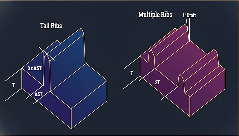
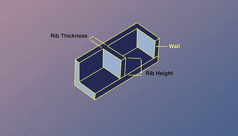
리브와 boss는 벽 두께와 상호작용하는 가장 일반적인 특징입니다. 리브의 경우: 기본 두께는 기준 벽의 50–60%여야 하고, 높이는 기준 벽의 3배를 넘지 않아야 하며, 여러 개의 얇은 리브가 하나의 높고 두꺼운 리브보다 더 좋습니다.
boss의 경우, 코어링이 해결책입니다 — 코어 핀을 사용하여 중심을 비워 균일한 벽 두께를 유지합니다. boss 외경은 hole 직경의 2–3배 이하로 해야 합니다. 이러한 비율을 따르는 부품은 사출 성형이 깨끗하게 이루어집니다. 사출 금형[3] 깨끗하게 성형됩니다; 이 기준을 벗어나는 부품은 지속적인 품질 문제를 발생시킵니다.
How Does Wall Thickness Affect Cycle Time?
In 사출 성형, 냉각 시간[4] 일반적으로 총 주기 시간의 50–70%를 나타내며, 가장 두꺼운 단면에 의해 결정됩니다.
| 명목 벽 두께 | 일반 냉각 시간 | 상대적 주기 비용 |
|---|---|---|
| 1.5 mm | 8–12초 | 1.0× (baseline) |
| 2.0 mm | 12–18초 | 1.3× |
| 2.5 mm | 18–25초 | 1.6× |
| 3.0 mm | 25–35초 | 2.0× |
| 4.0 mm | 40–60초 | 3.0× |
2.0 mm에서 3.0 mm 벽으로 변경하면 순수 주기 시간만으로도 부품 제조 비용이 약 2배 증가합니다. 구조적으로 가능할 때 얇은 벽 설계는 사출 성형에서 가장 높은 ROI 최적화 중 하나입니다.
What Are the Most Common Wall Thickness Mistakes?
- 균일한 두께를 무시함. 두께 분석 없이 설계된 부품은 명목 두께의 절반인 부분과 함께 명목보다 3배 더 두꺼운 영역이 있어, 싱크 마크, 뒤틀림 및 주기 시간 증가를 유발합니다.
- 강도를 위한 과도한 두께 증가. 리브가 더 가볍고, 생산이 더 빠르며, 치수 안정성이 더 높을 때 엔지니어는 재료를 추가합니다.
- 리브 비율을 무시함. 명목 벽의 80–100%에 해당하는 리브는 심한 싱크 마크를 유발합니다. 50–60% 규칙은 모든 재료에 적용됩니다.
- 급격한 두께 변화. 테이퍼 없는 급격한 변화는 응력 집중점과 외관 결함을 생성합니다.
- 유동 시뮬레이션을 실행하지 않음. 현대적 도구는 충전 패턴, 압력 및 냉각을 높은 정확도로 예측합니다. 복잡한 부품에서 시뮬레이션을 생략하면 일반적으로 손실이 발생합니다.
What Should You Check Before Submitting Your Design?
금형 제작을 위해 설계를 제출하기 전에 이 체크리스트를 확인하세요. 각 항목은 확인하는 데 몇 초밖에 걸리지 않으며 비용이 많이 드는 금형 수정을 방지할 수 있습니다.
| Check Item | 통과 기준 |
|---|---|
| 재료 이상 범위 내 명목 벽 | ✓ |
| 벽 두께 변동은 명목치의 ±25% 이내 | ✓ 또는 기재됨 |
| 모든 리브 ≤ 기준 벽의 60% | ✓ |
| 두께 전이는 3:1 테이퍼 사용 | ✓ |
| boss 외경 ≤ hole 직경 ×3 | ✓ |
| 가장 두꺼운 단면 식별 및 검토 완료 | ✓ |
| 유동 시뮬레이션 완료 | ✓ |
금형 제작 전 벽 두께 최적화는 필수적입니다 — 두께 문제를 해결하는 가장 저렴한 곳은 CAD에서, 금형에서 아닙니다.
벽 두께에 관한 자주 묻는 질문
사출 성형의 최소 벽 두께는 얼마인가요?
대부분의 엔지니어링 열가소성 수지(ABS, PC, 나일론)에서 0.8mm는 짧은 유동 경로에 대한 실질적 최소값입니다. PP 및 PE 같은 고유동성 재료는 0.5mm까지 얇게 할 수 있습니다. 이러한 최소값은 높은 사출 압력을 요구하며 불완전 충전의 위험을 수반합니다.
부품 전체에서 벽 두께가 달라질 수 있나요?
예, 하지만 변동은 공칭 벽 두께의 ±25% 이내로 유지되어야 하며, 서로 다른 두께 사이에는 3:1 테이퍼 비율을 사용한 점진적인 전환을 적용해야 합니다.
벽 두께는 수축과 어떻게 관련되어 있나요?
두꺼운 부분은 더 많은 재료가 냉각되고 수축하기 때문에 더 많이 줄어듭니다. 이러한 차등 수축은 사출 성형 부품의 뒤틀림의 주요 원인입니다.
벽 두께가 부품 강도에 영향을 미치나요?
네, 하지만 선형적으로는 아닙니다. 벽 두께를 두 배로 하면 굽힘 강성이 두 배 이상 증가합니다(두께의 세제곱으로 증가합니다). 그러나 벽을 두껍게 하면 잔류 응력과 공극 발생 위험도 증가합니다. 적절하게 비례된 리브는 종종 더 나은 강도-중량 성능을 달성합니다.
벽 두께는 어떻게 측정하나요?
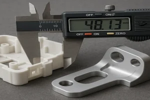
CAD 소프트웨어(SolidWorks, Creo 및 대부분의 MCAD 패키지에 내장됨)의 두께 분석 도구를 사용하세요. 실제 부품에서는 비파괴 측정을 위해 초음파 두께 측정기를 사용하거나, 절단된 단면을 캘리퍼로 직접 측정합니다. 생산 과정에서는 초음파 측정이 지속적인 품질 모니터링의 표준 방법입니다.
씬월 몰딩이란 무엇인가요?
박벽 성형은 벽 두께가 1.0mm 미만(전자제품 외관용으로는 0.3mm까지 얇은 경우도 있음)인 부품을 의미합니다. 매우 높은 압력(200+ MPa)을 필요로 하는 고속 기계와 특수 금형 설계가 요구됩니다.
Bottom line: 벽 두께를 1.5–3.0mm 사이로 유지하고 ±25% 균일성을 유지하며, 3:1 테이퍼 전환을 사용하고 리브를 명목 벽의 50–60%로 유지하세요. 이 네 가지 규칙은 벽 두께 관련 결함의 90%를 방지합니다.
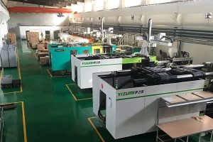
설계 초기에 결정된 벽 두께는 부품이 효율적으로 성형될지 아니면 생산 과정 전체에서 문제를 일으킬지를 결정합니다. 400+ 이상의 소재를 통해 수천 개의 벽 두께 설계를 최적화한 엔지니어들로부터 DFM 검토를 원한다면, ZetarMold의 우리 팀에 연락하세요. 우리는 Shanghai 시설에서 45대의 사출 성형 기계(90T–1850T)를 운영하며, 30+ 이상의 영어를 구사하는 프로젝트 매니저가 도움을 준비하고 있습니다.




 EN
EN  ES
ES  FR
FR  DE
DE  PT
PT  AR
AR  RU
RU  JA
JA  KO
KO  IT
IT  NL
NL  TR
TR  PL
PL 