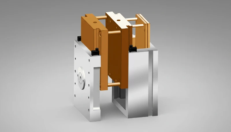
Ein Kunststoffteil aus einer Form zu entnehmen, klingt einfach – bis es beim Auswerfen feststeckt, zerkratzt oder sich verzieht. Ob das Teil reibungslos ausgeworfen wird oder hängen bleibt, hängt häufig von einer einzigen Entscheidung bei der Konstruktion der Spritzgussform ab: der Entformungsschräge1. In mehr als 20 Jahren Teilefertigung mit dem Spritzgießprozess im Werk von ZetarMold in Shanghai haben wir erlebt, wie die richtige Entformungsschräge Produktionszeit spart, Ausschuss reduziert und die Lebensdauer der Form verlängert. Dieser Leitfaden zeigt, wie sich wirksame Entformungsschrägen mit weniger Spekulation auslegen lassen.
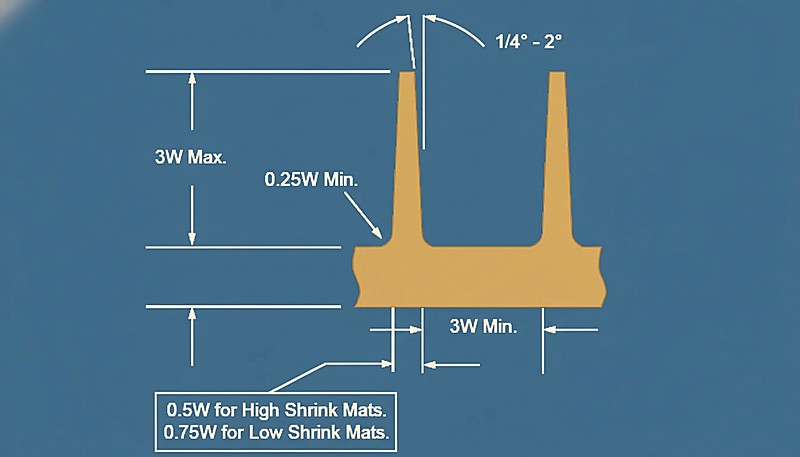
- Ein Entwurfswinkel ist die an den vertikalen Wandungen einer Formkavität angelegte Verjüngung, um ein glattes Entfernen des Teils zu ermöglichen
- Standardausformung liegt zwischen 0,5° und 3°, abhängig von Material, Oberflächengüte und Bauteilgeometrie
- Texturierte Oberflächen benötigen 3–7° Ausformung – deutlich mehr als polierte Oberflächen
- Null Auszug ist möglich mit bestimmten Materialien und Formdesigns, birgt aber Produktionsrisiken
- Ausformung immer von Toleranzmessungen des Bauteils ausschließen, außer explizit anders angegeben
Was ist ein Entformungswinkel beim Spritzgießen?
Eine Entformungsschräge beim Spritzgießen wird durch die in diesem Abschnitt erläuterten Funktionen, Randbedingungen und Abwägungen bestimmt. Wenn Sie Anbieter vergleichen oder die Beschaffung planen, behandelt unser Leitfaden zur Auswahl eines Spritzgusslieferanten die Vorbereitung der Angebotsanfrage, die Qualifizierung und die Prüfung kommerzieller Risiken.
Ein Auszugwinkel ist die geringe Verjüngung – oder Neigung – die in die vertikalen Wandungen einer Formkavität und Kern eingearbeitet ist. Statt perfekt parallelen Seitenwandungen sind die Kavitätenwandungen um Bruchteile eines Grads bis mehrere Grad nach außen geneigt, wodurch beim Öffnen der Form ein Freiraum zwischen dem festen Plastik und dem Stahl entsteht.
Stellen Sie sich eine Eiswürfelform vor: Durch die konische Form jedes Fachs lassen sich die Würfel leicht herausdrücken. Ohne diese Schräge müssten Sie die Form verdrehen oder erwärmen oder die Würfel mit Kraft herauslösen. Beim Spritzgießen gilt dasselbe Prinzip – allerdings mit wesentlich höheren Anforderungen, wenn Präzisionsteile in großen Stückzahlen gefertigt werden.
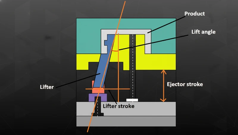
Auszugwinkel existieren auf beiden Seiten der Form. Die Kavitätenseite (A-Seite oder Vorderform) und die Kernseite (B-Seite oder Hinterform) haben jeweils ihren eigenen Auszug. Für Formen mit Seitenaktionen – wie Schieber oder Lifter – folgt die Auszugrichtung der Bewegung dieser Seitenkerne statt der Hauptteilunglinie.
In unserem Werk in Shanghai haben wir über 20+ Jahre hinweg Richtlinien für Entformungsschrägen anhand Tausender Werkzeugkonstruktionen verfeinert. Unser hauseigener Werkzeugbau fertigt monatlich 100+ Werkzeugsätze und liefert uns dadurch umfangreiche Praxisdaten dazu, welche Entformungswerte in der Produktion tatsächlich funktionieren.
Warum benötigt jedes Spritzgießwerkzeug einen Entwurfswinkel?
Dieser Abschnitt behandelt, ob jede Spritzgussform einen Auszugwinkel benötigt und dessen Auswirkung auf Kosten, Qualität, Timing oder Beschaffungsrisiko. Ohne Auszugwinkel bildet das Plastikteil beim Abkühlen und Schrumpfen einen Vakuumverschluss gegen die Formwandung. Wenn die Form sich öffnet oder die Ausstoßstifte drücken, muss dieser Verschluss durch Kraft gebrochen werden – was zu Abrieb, Kratzen, Verformung oder kompletter Verklemmung führt.
Folgendes geschieht bei unzureichender oder fehlender Entformungsschräge:
Ein richtig ausgelegter Entwurfswinkel eliminiert diese Probleme, indem beim ersten Öffnen der Form ein kleiner Spalt zwischen Teil und Formwand entsteht. Das Teil wird sauber, konsistent und ohne Beschädigung freigesetzt – Zyklus nach Zyklus.
"Eine Entformungsschräge von 1° je Seite ist für die meisten Teile mit polierter Oberfläche und einer Tiefe unter 50 mm ausreichend."True
Für standardpolierte Oberflächen mit üblichen technischen Kunststoffen wie ABS oder PP bieten 0,5° bis 1° pro Seite ausreichenden Freiraum für Ausstoß bei Teilen bis 50 mm Tiefe. Tieferere Teile oder strukturierte Oberflächen benötigen mehr Auszug, um die erhöhte Oberflächenkontaktfläche zu kompensieren.
"Entformungsschrägen sind nur auf der kavitätsseitigen A-Seite der Form erforderlich."False
Ein Auszug ist sowohl auf der Kavitäten- als auch auf der Kernseite erforderlich. Die Kernseite benötigt oft mehr Auszug, weil das Plastik beim Abkühlen darauf schrumpft und einen stärkeren Griff erzeugt als auf der Kavitätenseite. Das Auslassen des Auszugs auf dem Kern ist eine häufige Ursache für Ausstoßfehler.
Welche sind die Standard-Auszugwinkelwerte nach Material?
Die Standardwerte der Entformungsschräge nach Material sind die in diesem Abschnitt erläuterten Hauptkategorien oder Optionen. Unterschiedliche Kunststoffe weisen unterschiedliche Schwindungsraten, Reibungskoeffizienten und Steifigkeitswerte auf – daher variiert die ideale Entformungsschräge je nach Material erheblich. Die folgende Praxistabelle basiert auf unserer Erfahrung mit 400+ Materialien bei ZetarMold.
| Werkstoff | Min Auszug (Poliert) | Empfohlener Auszug | Anmerkungen |
|---|---|---|---|
| ABS | 1° | 1–2° | Gute Steifigkeit; Standardausformung funktioniert gut |
| PC (Polycarbonat) | 1° | 1.5–2° | Starr; höhere Schwindung benötigt mehr Ausformung |
| PP (Polypropylen) | 0.5° | 0.5–1° | Flexibel; kann geringere Auszugwerte verwenden |
| PA6/PA66 (Polyamid) | 0.5° | 0.5–1.5° | Niedrige Reibung hilft; glasfaserverstärkt benötigt 1–3° |
| PS (Polystyrol) | 2° | 2–3° | Spröde; benötigt mehr Entwurfswinkel, um Bruch zu verhindern |
| POM (Polyacetal) | 0.5° | 1–1.5° | Niedrige Reibung, aber hohe kristalline Schwindung |
| PMMA (Acryl) | 1.5° | 2–3° | Transparent; verkratzt leicht, benötigt großzügige Ausformung |
| TPU/TPE | 0.5° | 0.5–1° | Elastisch; Material dehnt sich während des Ausstoßes |
| Glasfaserverstärkt (alle) | 1.5° | 2–3° | Abrasive Fasern erhöhen die Reibung auf Formwandungen |
Diese Werte setzen polierte Formoberflächen voraus. Bei strukturierten Oberflächen sind je nach Strukturtiefe 1° bis 4° hinzuzurechnen – ein Thema, das wir weiter unten im Abschnitt zur Oberflächenbeschaffenheit2 ausführlich behandeln. Entscheidend ist: Steife, spröde und glasfaserverstärkte Materialien benötigen immer größere Entformungsschrägen als flexible Kunststoffe mit geringer Reibung.
Wie berechnet man die benötigte Ausformung?
Dieser Abschnitt erläutert die Berechnung der erforderlichen Entformungsschräge und deren Auswirkungen auf Kosten, Qualität, Zeitplan oder Beschaffungsrisiko. Entformungsschrägen werden häufig anhand von Erfahrungswerttabellen gewählt; für einen präziseren Ausgangswert steht jedoch eine einfache geometrische Berechnung zur Verfügung.
Die grundlegende Formel verbindet Schrägungswinkel (α), Teilhöhe (H) und den Größenunterschied zwischen der Ober- und Unterseite der schrägen Wand:
tan α = (D − d) / (2 × H)
Hierbei ist α der Schrägungswinkel pro Seite, D ist die größere Dimension (an der Trennkante), d ist die kleinere Dimension (am Boden der Ziehteile), und H ist die Gesamthöhe der Wand.
Beispiel: Bei einem Teil mit 60 mm Wandtiefe ist für ein leichtes Entformen auf jeder Seite ein Freigang von 0.5 mm erforderlich. Mit der Formel ergibt sich: tan(α) = 0.5 / 60 = 0.0083 und damit α ≈ 0.48°. Aufgerundet sind das 0.5° je Seite – genau das empfohlene Minimum für ein poliertes PP-Teil dieser Tiefe.
Unsere 8 erfahrenen Ingenieure verwenden Moldflow-Simulation3 zusammen mit der geometrischen Formel, um Entformungswinkel vor der Stahlbearbeitung zu prüfen. Mit 47 Spritzgießmaschinen von 90T bis 1850T können wir die gewählten Entformungswinkel durch reale Spritzgießversuche validieren – ein Schritt, den die meisten reinen Konstruktionsfirmen auslassen.
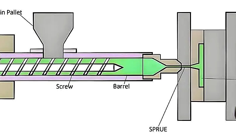
Welche Faktoren beeinflussen die Ausformungsauswahl?
Dieser Abschnitt handelt von Faktoren, die die Zugentlastungswinkelauswahl beeinflussen und deren Wirkung auf Kosten, Qualität, Timing oder Beschaffungsrisiko. Neben dem Material selbst bestimmen mehrere Design- und Produktionsfaktoren, wie viel Zugentlastung Sie benötigen. Die Ignorierung eines davon kann zu Produktionsproblemen führen, die nach dem Bau der Form kostspielig zu fixieren sind.
Teiletiefe oder Wandhöhe: Tiefere Konturen erfordern eine sorgfältige Wahl der Entformungsschräge. Eine Schräge von 0.5° erzeugt an einer 10 mm hohen Wand nur 0.09 mm Freigang je Seite, an einer 100 mm hohen Wand dagegen 0.87 mm, was meist ausreicht. Grundsätzlich gewinnt die Entformungsschräge mit zunehmender Wandtiefe an Bedeutung, auch wenn der Winkel selbst mitunter kleiner ausfallen kann.
Wanddicke: Dickere Wände schwinden beim Abkühlen stärker und legen sich dadurch enger um den Kern. Überschreitet die Wanddicke 3 mm, sollte die Entformungsschräge gegenüber der Grundempfehlung für das Material um 0.5° bis 1° erhöht werden.
Kern- gegenüber Kavitätsseite: Kunststoff schrumpft beim Abkühlen auf den Kern (B-Seite). Deshalb benötigt die Kernseite im Allgemeinen 0.5° bis 1° mehr Entformungsschräge als die Kavitätsseite. Besonders wichtig ist dies bei Teilen mit tiefen Domen oder Rippen, an denen sich der Kunststoff eng um den Stahl legt.
Verstärkungsrippen und Dome: Rippen unter 3 mm Höhe können mit 0.5° Entformungsschräge ausgeführt werden. Bei 3–5 mm sind 1° und über 5 mm 1.5° vorzusehen. Für Dome gilt dieselbe Abstufung, jedoch jeweils zuzüglich 0.5°, da sie beim Abkühlen um den Kernstift schwinden.
"Strukturierte Oberflächen erfordern bei gleicher Bauteilgeometrie größere Entformungsschrägen als polierte Oberflächen."True
Oberflächentextur erzeugt mikroskopische Hinterschneidungen, die das gehärtete Plastik während des Ausstoßens physikalisch greifen. Je rauer die Textur, desto mehr Zugentlastung ist erforderlich, um das Teil ohne Ziehen freizugeben.
"Der Entformungswinkel sollte stets in der Maßtoleranzspezifikation des Bauteils enthalten sein."False
In der Standardformenkonstruktionspraxis wird der Zugentlastungswinkel meist als Werkzeug- und Freigabefunktion behandelt, nicht als normale dimensionale Toleranz. Wenn Zugentlastung eine kritische Toleranz beeinflussen muss, sollte dies während DFM explizit markiert werden.
Wie beeinflussen Oberflächentexturen die Ausformungsanforderungen?
Die Oberflächengüte ist einer der am meisten unterschätzten Faktoren bei der Schrägungswinkelgestaltung. Eine rein kosmetisch aussehende Textur erzeugt tatsächlich winzige Hinterschneidungen, die das Auswerfen behindern – und die Schrägung muss diesen mechanischen Verschluss kompensieren.
| Oberfläche | Texturtiefe | Empfohlener Auszug |
|---|---|---|
| Poliert (SPI A-1 bis A-3) | < 0,001 mm | 0.5°–1° |
| Feines Matt (SPI B-1 bis B-3) | 0.001–0.01 mm | 1°–1.5° |
| Mittlere Textur (MT11010) | 0.01–0.05 mm | 1.5°–3° |
| Grobe Textur (MT11020) | 0.05–0.1 mm | 3°–5° |
| Ledergrain / tiefe Textur | 0.1–0.2+ mm | 5°–7°+ |
Eine praktische Faustregel: Für jede 0,01 mm Texturtiefe addieren Sie etwa 1° Schrägung. Eine Textur mit 0,05 mm Tiefe benötigt also etwa 5° Schrägung für ein sauberes Auswerfen. Diese Beziehung ist linear genug, um in frühen DFM-Reviews nutzbar zu sein, sogar bevor physische Texturproben von Ihrem Werkzeuglieferanten verfügbar sind.
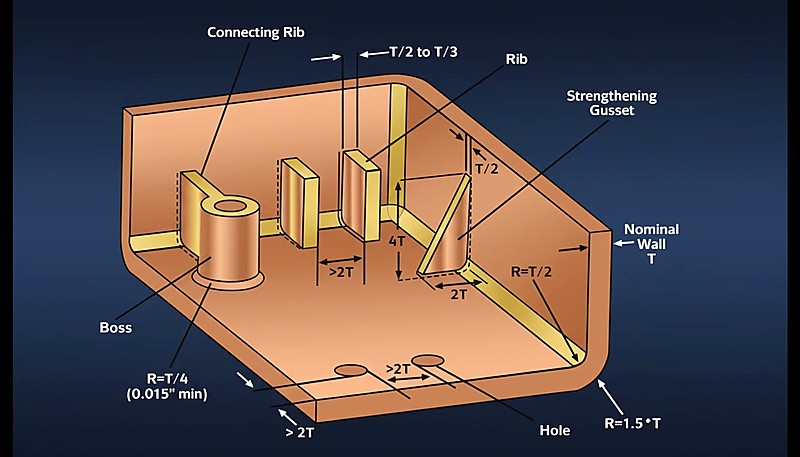
Aus diesem Grund klären wir bei ZetarMold die gewünschte Oberflächenqualität stets früh im Konstruktionsprozess. Ein Wechsel von einer polierten Oberfläche zu einer Narbenstruktur mitten im Projekt kann eine Neukonstruktion des gesamten Entformungsschrägenkonzepts der Kavität erfordern — vor dem Zerspanen des Stahls ist dies wesentlich einfacher als danach.
Welche sind die häufigen Auszugwinkel-Fehler, die zu vermeiden sind?
Die häufigsten Zugentlastungswinkel-Fehler, die vermieden werden sollten, sind die Hauptkategorien oder Optionen, die in diesem Abschnitt erklärt werden. Nach der Überprüfung von Tausenden von Formenkonstruktionen über zwei Jahrzehnte in unserem Shanghai-Werk sehen wir dieselben Zugentlastungswinkel-Fehler wiederholt. Diese Fehler führen zu erhöhten Ausschussraten, kostspieligen Formenänderungen und Produktionsverzögerungen, die mit einer ordentlichen Planung während der DFM-Phase vermieden worden könnten. Hier sind die häufigsten – und wie Sie sie in Ihrem nächsten Projekt vermeiden können.
Fehler 1: Keine Entformungsschräge an senkrechten Wänden. Manche Konstrukteure nehmen an, enge Toleranzen erforderten einen Winkel von null Grad. Tatsächlich führt eine fehlende Entformungsschräge fast zwangsläufig zum Festhaften, sofern nicht mit flexiblen Materialien wie TPU gearbeitet wird. Ist eine nahezu senkrechte Wand zwingend erforderlich, sollte anstelle einer geraden vertikalen Wand eine abgestufte oder versetzte Trennlinie erwogen werden.
Fehler 2: Uneinheitliche Richtung der Entformungsschrägen. Alle Entformungsschrägen auf derselben Seite müssen in dieselbe Richtung geneigt sein – zur Trennlinie hin. Unterschiedliche Richtungen erzeugen unbeabsichtigte Hinterschneidungen, die das Auswerfen vollständig verhindern und im CAD häufig schwer zu erkennen sind, bevor die Form gebaut wurde.
Fehler 3: Schwindungseffekte auf der Kernseite werden ignoriert. Kunststoff schrumpft beim Abkühlen auf den Kern. Wird auf Kavitäts- und Kernseite dieselbe Entformungsschräge verwendet, ist der Auswerfwiderstand auf der Kernseite deutlich höher. Geben Sie der Kernseite stets zusätzlich 0.5°–1° Entformungsschräge, um diesen schwindungsbedingten Klemmeffekt auszugleichen.
Fehler 4: Anforderungen der Nachbearbeitung werden vergessen. Soll das Teil nach dem Formen ultraschallgeschweißt, verrastet oder spanend bearbeitet werden, darf die Entformungsschräge Passflächen oder Ausrichtungsmerkmale nicht beeinträchtigen. Planen Sie die Schräge gleichzeitig aus Sicht des Formprozesses und der Montage, um kostspielige Neukonstruktionen zu vermeiden und eine reibungslose Weiterverarbeitung sicherzustellen.
"Die Zugabe einer Entformungsschräge entsprechend der Texturtiefe ist ein zuverlässiger Ausgangspunkt für strukturierte Werkzeugoberflächen."True
Eine allgemeine Werkstattregel ist, den Schlichtzug zu erhöhen, wenn die Textur tiefer wird, und dann den Wert gegen die Daten des Texturlieferanten und die tatsächliche Ausstoßrichtung zu verifizieren. Dies verhindert Ziehen und Abschürfen auf kosmetischen Oberflächen.
"Ein größerer Entformungswinkel führt immer zu besseren Auswerfergebnissen und hat keine Nachteile."False
Übermäßiger Zug kann die Wandstärke, den Montagepassung, das Aussehen und das Toleranzverhalten ändern. Der Zug sollte für das Teil optimiert werden, statt blind maximiert.
Die Arbeit mit 400+ Materialien unter den Qualitätssystemen ISO 9001 und ISO 13485 bedeutet, dass wir die Ergebnisse von Entformungsschrägen für praktisch jeden gängigen technischen Kunststoff dokumentiert haben. Unsere Prozessdatenbank hilft uns, Risiken im Zusammenhang mit Entformungsschrägen zu erkennen, bevor die Werkzeugkonstruktion abgeschlossen ist.
Wie optimiert man Entwurfswinkel für komplexe Teile?
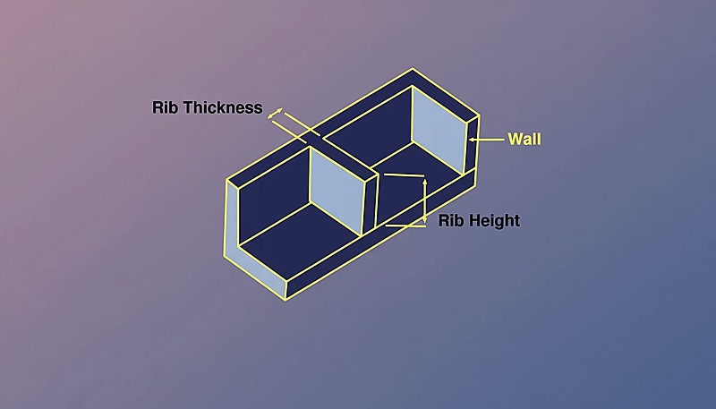
Einfache Teile mit geraden Wänden sind unkompliziert. Reale Spritzgussteile besitzen jedoch Rippen, Dome, Gewinde, Hinterschneidungen und Schnappverbindungen – jeweils mit eigenen Anforderungen an den Entformungswinkel. So beherrschen Sie die Komplexität, ohne die Spritzgießbarkeit zu beeinträchtigen.
Teile mit Schiebern und Schrägauswerfern: Die Entformungsschräge seitlicher Formelemente folgt der Bewegungsrichtung des Schiebers, nicht der Haupttrennlinie. An Schieberflächen sind mindestens 3° vorzusehen, damit sich der Stahl vom Kunststoff löst, bevor der Schieber zurückfährt. Bei schrägen Auswerfern muss die Entformungsschräge den zusammengesetzten Bewegungswinkel des Auswerfers berücksichtigen.
Tiefziehteile: Bei Wänden mit mehr als 100 mm Tiefe empfiehlt sich eine abgestufte Entformungsschräge – mit einem größeren Winkel nahe der Trennlinie, der sich zum Boden hin verkleinert. So bleibt die Wanddicke gleichmäßig, während an den entscheidenden Stellen genügend Freigang für das Entformen vorhanden ist.
Mehrkavitätenformen: Stellen Sie sicher, dass alle Kavitäten dieselben Entformungsschrägen verwenden, damit Auswerfkräfte und Zykluszeiten über die gesamte Form hinweg gleich bleiben. Unterschiedliche Schrägen zwischen den Kavitäten verursachen häufig schwer zu diagnostizierende Qualitätsunterschiede von Kavität zu Kavität.
Verifizierung durch Simulation: Bevor eine komplexe Anordnung von Entformungsschrägen endgültig festgelegt wird, sollte eine Formfüllsimulation auf mögliche Auswerfprobleme prüfen. Programme wie MOLDFLOW können vor dem ersten Zerspanen des Stahls vorhersagen, wo das Teil festhaften wird, wo sich Auswerfkräfte konzentrieren und ob die Entformungsschräge ausreicht.
Wie sollte man die Entwurfswinkelgestaltung angehen?
Dieser Abschnitt behandelt den Ansatz zur Auslegung von Entformungsschrägen und dessen Auswirkungen auf Kosten, Qualität, Termine oder Beschaffungsrisiken. Die richtige Entformungsschräge auszulegen ist nicht kompliziert, erfordert jedoch Sorgfalt: beim zu verarbeitenden Material, der benötigten Oberflächengüte, der Wandtiefe und der Komplexität der Bauteilgeometrie. Sind diese Faktoren richtig ausgelegt, lassen sich Ihre Bauteile sauber entformen, Ihre Formen halten länger und Ihre Produktionskosten sinken.
Bei ZetarMold bringt unser Engineering-Team 20+ Jahre Erfahrung in der Werkzeugkonstruktion in jedes Projekt ein — von einfachen Zweiplattenwerkzeugen bis zu komplexen Werkzeugen mit mehreren Schiebern. Wenn Sie ein neues Teil konstruieren und fachkundige Rückmeldung zu Entformungsschrägen oder anderen Entscheidungen der Werkzeugkonstruktion wünschen, unterstützen wir Sie gern.
Häufig gestellte Fragen
Was ist der minimale Entwurfswinkel für Spritzguss?
Der absolute Mindestzugwinkel ist 0,5° pro Seite für flexible Materialien wie PP oder TPU mit polierten Formoberflächen. Für starre Engineering-Kunststoffe wie ABS oder PC, beginnen bei mindestens 1°. Unter diesen Werte gehen riskiert Teilfestkleben, Oberflächenabschaben und inkonsistente Ausstoßkräfte, die sowohl das Teil und die Form über Zeit beschädigen können. Immer mehr Zug für strukturierte oder genarbte Oberflächen hinzufügen, und erwägen den Winkel zu erhöhen, wenn Ihr Teil tiefe Wände oder komplexe Geometrie hat. In Produktionsumgebungen, die Kosten von zusätzlichen 0,5° Zug sind vernachlässigbar gegenüber den Kosten von Fixieren eines Festklebenproblems nach Formbau.
Kann man ohne Zugwinkel spritzgießen?
Ja, aber nur in sehr spezifischen Fällen – typischerweise mit flexiblen Materialien wie TPU oder Silikon, die sich beim Auswerfen strecken und komprimieren können, ohne dauerhaft verformt zu werden. Selbst dann erhöht Null-Entwurf die Auswerferkraft, Zykluszeitschwankungen und Fehlerraten erheblich. Die meisten Produktionswerkzeuge verwenden mindestens 0,25°–0,5° Entwurf als absolutes Minimum, selbst für Teile, die nominell Null-Entwurf erfordern. Wenn Ihr Design wirklich keinen Konus tolerieren kann, sollten Sie alternative Strategien wie zusammenklappbare Kerne, geteilte Hohlräume oder einen leichten Versatz in der Trennlinie in Betracht ziehen, um eine gerichtete Freigabefreiheit zu schaffen.
Wie beeinflusst der Entwurfswinkel die Teiletoleranz?
Der Entwurfswinkel wird normalerweise von der Toleranzzone des Teils ausgeschlossen – Maße werden an einer spezifizierten neutralen Ebene oder einem Bezug gemessen, nicht an den konischen Wänden selbst. Dies ist eine Standardpraxis, die durch ISO 8062 und die meisten in der Branche verwendeten Werkzeugdesign-Handbücher etabliert ist. Wenn Ihre Anwendung erfordert, dass der Entwurf in die Toleranzzone einbezogen wird (was selten und meist auf Präzisionsmedizin- oder optische Komponenten beschränkt ist), muss dies explizit in der Teilezeichnung angegeben werden. Für die meisten Spritzgussteile ist der Entwurfskonus für die funktionalen Maße, die wichtig sind, transparent.
Welcher Zugwinkel ist für strukturierte Oberflächen benötigt?
Strukturierte Oberflächen benötigen deutlich größere Entformungswinkel als polierte Oberflächen, da das Strukturmuster mikroskopische Hinterschnitte erzeugt, die das Kunststoffteil beim Auswerfen festhalten. Als praxisgerechte Regel gilt: je 0.01 mm Strukturtiefe etwa 1° Entformungswinkel vorsehen. Feine Mattstrukturen mit etwa 0.01 mm Tiefe benötigen ungefähr 1°–1.5°, mittlere Strukturen 1.5°–3° und tiefe Ledernarbungen mit mehr als 0.1 mm Tiefe 5°–7° oder mehr. Ziehen Sie stets das spezifische Empfehlungsblatt Ihres Strukturlieferanten heran, da unterschiedliche Strukturierungsverfahren bei gleichem optischem Erscheinungsbild unterschiedliche Entformungswinkel erfordern können.
Wie fügt man Zug zu einem bestehenden Teilentwurf hinzu?
In meisten CAD-Systemen kann Zug als parametrische Funktion angewendet werden, die ausgewählte Flächen um einen neutralen Plan oder Trennkante um einen bestimmten Winkel neigt. Für komplexe Teile, Zug in Etappen anwenden – beginnen mit Kernwandflächen, dann Kavitätenwandflächen, gefolgt von Rippen, Bossen und anderen sekundären Features. Verifizieren, dass alle Zugrichtungen konsistent sind und zur Trennkante zeigen. Wenn das Teil bereits werkzeuggebaut wurde und Sie unzureichenden Zug finden, erhöhen erfordert Schweißen und Nachbearbeitung der betroffenen Kavitätenoberflächen, was kostspielig und zeitaufwendig ist – ein weiterer Grund, Zug beim ersten Mal richtig zu machen.
Benötigt die Kernseite mehr Entwurf als die Hohlraumseite?
Ja, in den meisten Fällen profitiert die Kernseite von zusätzlichem Entwurf. Da sich der Kunststoff während der Kühlphase des Spritzgusszyklus auf den Kern zusammenzieht, erfährt die Kernseite beim Auswerfen deutlich mehr Reibung und Haltekraft. Es ist Standard in der Werkzeugkonstruktion, auf der Kernseite im Vergleich zur Hohlraumseite 0,5°–1° mehr Entwurf hinzuzufügen. Dieser Unterschied ist besonders wichtig für Tiefziehteile, Komponenten mit hohen Buckeln und Teile mit dichten Rippenmustern, bei denen die kombinierte Schrumpfkraft auf den Kernstahl konzentriert ist.
Entformungsschräge: Als Entformungsschräge bezeichnet man die Neigung, durch die sich geformte Wände aus der Kavität oder vom Kern lösen, ohne am Werkzeug zu schleifen und dabei das Teil zu zerkratzen oder zu verformen. ↩
Oberflächenbeschaffenheit: Die Oberflächenbeschaffenheit bezeichnet die Strukturqualität der Oberfläche einer Formkavität, die sich unmittelbar auf die Reibung beim Entformen auswirkt – tiefere Strukturen erfordern größere Entformungsschrägen, damit das Teil sauber ausgeworfen wird. ↩
Moldflow-Simulation: Eine Moldflow-Simulation ist ein Simulationswerkzeug für das Spritzgießen, das Füllverlauf, Kühlverhalten und Auswerfkräfte prognostiziert. So kann die Entformungsschräge vor der Werkzeugfertigung optimiert werden. ↩