 Saltar para o conteúdo

tan(α) = (D − d) / (2 × H) conceção de moldes de injeção decision: ângulo de inclinação1. In our 20+ years of building parts through the processo de moldagem por injeção na fábrica da ZetarMold em Xangai, vimos como o ângulo de saída correto poupa tempo de produção, reduz desperdício e prolonga a vida útil do molde. Este guia detalha como projetar ângulos de saída que funcionam com menos suposições.
- A draft angle is the taper applied to vertical walls of a mold cavity to allow smooth part removal
- Standard draft ranges from 0.5° to 3° depending on material, surface finish, and part geometry
- Textured surfaces require 3–7° of draft—significantly more than polished surfaces
- Zero draft is possible with specific materials and mold designs, but it carries production risks
- Always exclude draft angle from part tolerance measurements unless explicitly specified otherwise
What Is a Draft Angle in Injection Molding?
A draft angle in injection molding is defined by the function, constraints, and tradeoffs explained in this section. If you are comparing vendors or planning procurement, our injection molding supplier sourcing guide covers RFQ prep, qualification, and commercial risk checks.
A draft angle is the slight taper—or slope—designed into the vertical walls of a mold cavity and core. Instead of perfectly parallel sidewalls, the cavity walls lean outward by a fraction of a degree to several degrees, creating clearance between the solidified plastic and the steel as the mold opens.
Pense nisso como numa forma de gelo: a forma cónica de cada compartimento permite que os cubos saiam facilmente. Sem esse ângulo, seria necessário torcer, aquecer ou forçar a saída dos cubos. O mesmo princípio aplica-se à moldação por injeção — exceto que as consequências são muito maiores quando se produzem peças de precisão em escala.
Draft angles exist on both sides of the mold. The cavity side (A-side, or front mold) and the core side (B-side, or rear mold) each have their own draft. For molds with side actions—such as sliders or lifters—the draft direction follows the movement of those side cores rather than the main parting line.
Na nossa fábrica de Xangai, passámos mais de 20 anos a aperfeiçoar as diretrizes de ângulos de saída em milhares de projetos de moldes. A nossa instalação interna de fabrico de moldes produz mais de 100 conjuntos de moldes por mês, o que nos dá dados extensivos do mundo real sobre quais valores de ângulo funcionam efetivamente na produção.
Why Does Every Injection Mold Need a Draft Angle?
Esta secção aborda a necessidade de um ângulo de saída em todos os moldes de injeção e o seu impacto no custo, qualidade, tempo ou risco de aprovisionamento. Sem um ângulo de saída, a peça de plástico cria uma vedação de vácuo contra a parede do molde durante o arrefecimento e a contração. Quando o molde abre ou os pinos ejetores empurram, essa vedação tem de ser quebrada à força, o que leva a riscos, marcas, deformação ou aderência total.
Eis o que acontece quando o ângulo de saída é insuficiente ou está em falta:
A properly designed draft angle eliminates these problems by creating a small gap between the part and mold wall the instant the mold begins to open. The part releases cleanly, consistently, and without damage—cycle after cycle.
“Um ângulo de saída de 1° por lado é suficiente para a maioria das peças com superfície polida com menos de 50 mm de profundidade.”Verdadeiro
For standard polished surfaces with common engineering plastics like ABS or PP, 0.5° to 1° per side provides adequate release clearance for parts up to 50 mm deep. Deeper parts or textured surfaces need more draft to compensate for increased surface contact area.
“Ângulos de saída são apenas necessários no lado A da cavidade do molde.”Falso
Draft is required on both the cavity and core sides. The core side often needs more draft because the plastic shrinks onto it during cooling, creating a tighter grip than on the cavity side. Skipping draft on the core is a common cause of ejection failures.
What Are the Standard Draft Angle Values by Material?
Os valores padrão de ângulo de saída por material são as principais categorias ou opções explicadas nesta secção. Diferentes plásticos têm diferentes taxas de retração, coeficientes de atrito e níveis de rigidez — o que significa que o ângulo de saída ideal varia significativamente consoante o material. Eis uma tabela de referência prática baseada na nossa experiência com mais de 400 materiais na ZetarMold.
| Material | Min Draft (Polished) | Recommended Draft | Notas |
|---|---|---|---|
| ABS | 1° | 1–2° | Good stiffness; standard draft works well |
| PC (Policarbonato) | 1° | 1.5–2° | Rigid; higher shrinkage needs more draft |
| PP (Polipropileno) | 0.5° | 0.5–1° | Flexible; can use lower draft values |
| PA6/PA66 (Nylon) | 0.5° | 0.5–1.5° | Low friction helps; glass-filled needs 1–3° |
| PS (Poliestireno) | 2° | 2–3° | Brittle; needs more draft to prevent cracking |
| POM (Acetal) | 0.5° | 1–1.5° | Low friction, but high crystalline shrinkage |
| PMMA (Acrylic) | 1.5° | 2–3° | Transparent; scratches easily, needs generous draft |
| TPU/TPE | 0.5° | 0.5–1° | Elastic; material stretches during ejection |
| Glass-filled (any) | 1.5° | 2–3° | Abrasive fibers increase friction on mold walls |
Estes valores assumem superfícies do molde polidas. Para acabamentos texturados, adicione 1° a 4° dependendo da profundidade da textura — um tópico que abordaremos em detalhe na acabamento da superfície2 section below. The key takeaway: rigid, brittle, and glass-filled materials always demand more draft than flexible, low-friction plastics.
How Do You Calculate the Required Draft Angle?
Esta secção aborda o cálculo do ângulo de saída necessário e o seu impacto no custo, qualidade, tempo ou risco de aprovisionamento. Embora os ângulos de saída sejam frequentemente escolhidos com base em tabelas de experiência, existe um cálculo geométrico simples que pode utilizar quando precisa de um ponto de partida mais preciso.
The fundamental formula relates draft angle (α), part depth (H), and the size difference between the top and bottom of the drafted wall:
tan(α) = (D − d) / (2 × H)
Uma regra comum da loja é aumentar o esboço à medida que a textura se torna mais profunda, depois verificar o valor com os dados do fornecedor da textura e a direção real de liberação. Isto evita arrastamentos e arranhões nas superfícies cosméticas.
Exemplo: Uma peça com 60 mm de profundidade de parede precisa de uma folga de 0,5 mm por lado para uma liberação fácil. Usando a fórmula: tan(α) = 0,5 / 60 = 0,0083, o que dá α ≈ 0,48°. Arredondando, são 0,5° por lado — exatamente o mínimo recomendado para uma peça em PP polida com essa profundidade.
Our 8 senior engineers use Moldflow simulation3 alongside the geometric formula to verify draft angles before cutting steel. With 47 injection molding machines from 90T to 1850T, we can validate draft choices through actual molding trials—a step most design-only firms skip.
What Factors Influence Draft Angle Selection?
Esta secção aborda os fatores que influenciam a seleção do ângulo de saída e o seu impacto no custo, qualidade, tempo ou risco de aprovisionamento. Para além do material em si, vários fatores de design e produção determinam a quantidade de ângulo de saída necessária. Ignorar qualquer um destes fatores pode levar a problemas de produção que são dispendiosos de corrigir após a construção do molde.
Part depth or wall height: Deeper draws require careful draft selection. A 0.5° draft on a 10 mm wall creates only 0.09 mm of clearance per side—but the same 0.5° on a 100 mm wall gives 0.87 mm, which is usually sufficient. As a rule, the deeper the wall, the more critical draft becomes, even though the angle itself can sometimes be smaller.
Espessura da parede: Paredes mais espessas retraem mais durante o arrefecimento, puxando com mais força contra o núcleo. Se a espessura da sua parede exceder 3 mm, considere aumentar o ângulo de saída em 0,5° a 1° acima da recomendação base do material.
Core vs. cavity side: Plastic shrinks onto the core (B-side) during cooling, so the core side generally needs 0.5° to 1° more draft than the cavity side. This is especially important for parts with deep bosses or ribs where the plastic wraps tightly around the steel.
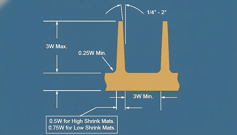
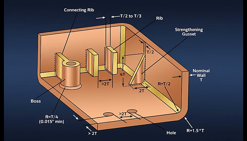
Reinforcing ribs and bosses: Ribs under 3 mm tall can use 0.5° draft. Between 3–5 mm, use 1°. Above 5 mm, allow 1.5°. Bosses follow the same progression but add 0.5° because they shrink around the core pin during cooling.
“Superfícies texturadas requerem ângulos de saída maiores do que superfícies polidas para a mesma geometria da peça.”Verdadeiro
Surface texture creates microscopic undercuts that physically grip the solidified plastic during ejection. The rougher the texture, the more draft is needed to release the part without dragging.
“O ângulo de saída deve ser sempre incluído na especificação de tolerância dimensional da peça.”Falso
In standard mold design practice, draft angle is usually treated as a tooling and release feature rather than a normal dimensional tolerance. If draft must affect a critical tolerance, it should be explicitly marked during DFM.
How Do Surface Textures Affect Draft Requirements?
Surface finish is one of the most underestimated factors in draft angle design. A texture that looks purely cosmetic actually creates tiny undercuts that resist ejection—and the draft must compensate for this mechanical interlock.
| Acabamento da superfície | Texture Depth | Recommended Draft |
|---|---|---|
| Polished (SPI A-1 to A-3) | < 0,001 mm | 0.5°–1° |
| Fine matte (SPI B-1 to B-3) | 0.001–0.01 mm | 1°–1.5° |
| Medium texture (MT11010) | 0.01–0.05 mm | 1.5°–3° |
| Coarse texture (MT11020) | 0.05–0.1 mm | 3°–5° |
| Leather grain / deep texture | 0.1–0.2+ mm | 5°–7°+ |
Uma regra prática útil: para cada 0,01 mm de profundidade da textura, adicione aproximadamente 1° de ângulo de saída. Assim, uma textura com 0,05 mm de profundidade necessita de cerca de 5° de ângulo de saída para libertar a peça de forma limpa. Esta relação é suficientemente linear para ser útil durante as revisões iniciais de DFM, mesmo antes de estarem disponíveis amostras físicas de textura do seu fornecedor de ferramentas.
Esta é uma das razões pelas quais na ZetarMold perguntamos sempre sobre o acabamento superficial numa fase inicial do processo de projeto. Mudar de polido para textura de couro a meio de um projeto pode exigir reprojetar todo o esquema de saída da cavidade — o que é muito mais fácil de fazer antes de se cortar o aço do que depois.
What Are the Common Draft Angle Mistakes to Avoid?
Os erros comuns de ângulo de saída a evitar são as principais categorias ou opções explicadas nesta secção. Após analisar milhares de designs de moldes ao longo de duas décadas na nossa fábrica de Xangai, vemos repetidamente os mesmos erros de ângulo de saída. Estes erros levam a taxas de refugo aumentadas, retrabalho dispendioso do molde e atrasos na produção que poderiam ter sido evitados com um planeamento adequado durante a fase de DFM. Aqui estão os mais comuns — e como evitá-los no seu próximo projeto.
Mistake 1: Zero draft on vertical walls. Alguns projetistas assumem que tolerâncias apertadas requerem ângulo de saída zero. Na realidade, ângulo de saída zero garante virtualmente que a peça fica presa, a menos que se esteja a trabalhar com materiais flexíveis como o TPU. Se absolutamente precisa de um ângulo de saída próximo de zero, considere usar uma linha de separação escalonada ou deslocada em vez de uma parede vertical reta.
Mistake 2: Inconsistent draft direction. Todos os ângulos de saída num determinado lado devem inclinar-se na mesma direção — em direção à linha de separação. Direções de saída mistas criam reentrâncias não intencionais que impedem totalmente a ejeção, e muitas vezes são difíceis de detetar no CAD até o molde estar construído.
Mistake 3: Ignoring shrinkage effects on the core side. Plastic shrinks onto the core during cooling. If you use the same draft on both cavity and core, the core side will have significantly more ejection resistance. Always give the core side an extra 0.5°–1° of draft to account for this shrinkage grip.
Mistake 4: Forgetting post-processing requirements. Se a peça for soldada por ultrassons, encaixada por pressão ou usinada após a moldagem, o ângulo de saída não deve interferir com as superfícies de acoplamento ou características de alinhamento. Planeie o seu ângulo de saída tanto da perspetiva da moldagem como da montagem simultaneamente para evitar redesenhos dispendiosos e garantir um processamento subsequente suave.
“Adicionar ângulo de saída para profundidade da textura é um ponto de partida confiável para superfícies de molde texturizadas.”Verdadeiro
A common shop rule is to increase draft as texture becomes deeper, then verify the value against the texture supplier data and the actual release direction. This prevents dragging and scuffing on cosmetic surfaces.
“Um ângulo de saída maior produz sempre melhores resultados de ejeção, sem desvantagens.”Falso
Excessive draft can change wall thickness, assembly fit, appearance, and tolerance behavior. Draft should be optimized for the part instead of blindly maximized.
Trabalhar com mais de 400 materiais sob sistemas de qualidade ISO 9001 e ISO 13485 significa que documentámos os resultados dos ângulos de saída para praticamente todos os plásticos de engenharia comuns. A nossa base de dados de processos ajuda-nos a sinalizar riscos relacionados com a saída antes do projeto do molde ser finalizado.
How Do You Optimize Draft Angles for Complex Parts?
Peças simples com paredes retas são diretas. Mas as peças moldadas por injeção do mundo real têm nervuras, bossas, roscas, reentrâncias e características de encaixe — cada uma com os seus próprios requisitos de ângulo de saída. Eis como lidar com a complexidade sem sacrificar a moldabilidade.
Parts with sliders and lifters: O ângulo de saída para ação lateral segue a direção de movimento do deslizador, não a linha de separação principal. Utilize um mínimo de 3° nas faces do deslizador para garantir que o aço se desprenda do plástico antes do deslizador se retrair. Para elevadores angulados, o ângulo de saída deve ter em conta o ângulo composto de movimento do elevador.
Deep-draw parts: For walls deeper than 100 mm, consider using a stepped draft—starting with a larger angle near the parting line and tapering to a smaller angle at the bottom. This maintains wall thickness uniformity while still providing adequate release clearance where it matters most.
Multi-cavity molds: Ensure all cavities use the same draft values to maintain consistent ejection forces and cycle times across the entire mold. Uneven draft between cavities is a common source of cavity-to-cavity quality variation that can be difficult to diagnose in production.
Simulation verification: Before finalizing any complex draft scheme, run a mold flow simulation to check for ejection issues. Tools like MOLDFLOW can predict where the part will stick, where ejection forces concentrate, and whether the draft is sufficient—all before any steel is cut.
Como Deve Abordar o Design do Ângulo de Saída?
Esta secção aborda a abordagem ao design do ângulo de saída e o seu impacto no custo, qualidade, tempo ou risco de aprovisionamento. Projetar o ângulo de saída correto não é complicado, mas requer atenção aos detalhes: o material que está a moldar, o acabamento superficial necessário, a profundidade das paredes e a complexidade da geometria da peça. Se acertar nestes fatores, as suas peças serão ejetadas de forma limpa, os seus moldes durarão mais tempo e os seus custos de produção diminuirão.
Na ZetarMold, a nossa equipa de engenharia traz mais de 20 anos de experiência em projeto de moldes para cada projeto — desde ferramentas simples de duas placas até moldes complexos de múltiplos deslizamentos. Se está a projetar uma nova peça e deseja feedback especializado sobre os seus ângulos de saída (ou qualquer outra decisão de projeto de molde), estamos aqui para ajudar.
Perguntas mais frequentes
What Is the Minimum Draft Angle for Injection Molding?
The absolute minimum draft angle is 0.5° per side for flexible materials like PP or TPU with polished mold surfaces. For rigid engineering plastics like ABS or PC, start at 1° minimum. Going below these values risks part sticking, surface scraping, and inconsistent ejection forces that can damage both the part and the mold over time. Always add more draft for textured or grained surfaces, and consider increasing the angle if your part has deep walls or complex geometry. In production environments, the cost of adding an extra 0.5° of draft is negligible compared to the cost of fixing a stuck-part problem after the mold is built.
Can You Injection Mold Without a Draft Angle?
Yes, but only in very specific cases—typically with flexible materials like TPU or silicone that can stretch and compress during ejection without permanent deformation. Even then, zero draft increases ejection force, cycle time variability, and defect rates significantly. Most production molds use at least 0.25°–0.5° of draft as an absolute minimum, even for parts that nominally require zero draft. If your design truly cannot tolerate any taper, consider alternative strategies like collapsible cores, split cavities, or a slight offset in the parting line to create directional release clearance.
How Does Draft Angle Affect Part Tolerance?
Draft angle is normally excluded from the part tolerance zone—dimensions are measured at a specified neutral plane or datum, not at the tapered walls themselves. This is standard practice established by ISO 8062 and most mold design handbooks used across the industry. If your application requires draft to be included in the tolerance zone (which is rare and usually limited to precision medical or optical components), it must be explicitly called out on the part drawing. For most injection molded parts, the draft taper is transparent to the functional dimensions that matter.
What Draft Angle Is Needed for Textured Surfaces?
Superfícies texturadas precisam de ângulos de saída significativamente maiores do que as polidas porque o padrão da textura cria reentrâncias microscópicas que agarram a peça de plástico durante a ejeção. Como regra prática, adicione aproximadamente 1° de saída por cada 0,01 mm de profundidade da textura. Texturas mate finas com cerca de 0,01 mm de profundidade precisam de cerca de 1°–1,5°, texturas médias precisam de 1,5°–3°, e texturas profundas de grão de couro que excedam 0,1 mm de profundidade requerem 5°–7° ou mais. Consulte sempre a folha de recomendações específica do seu fornecedor de texturas, pois diferentes processos de texturização podem ter requisitos de saída diferentes para a mesma aparência visual.
How Do You Add Draft to an Existing Part Design?
In most CAD systems, you can apply draft as a parametric feature that tilts selected faces by a specified angle around a neutral plane or parting line. For complex parts, apply draft in stages—start with core-side walls, then cavity-side walls, followed by ribs, bosses, and other secondary features. Verify that all draft directions are consistent and point toward the parting line. If the part has already been tooled and you discover insufficient draft, increasing it requires welding and re-machining the affected cavity surfaces, which is expensive and time-consuming—another reason to get draft right the first time.
Does the Core Side Need More Draft Than the Cavity Side?
Yes, in most cases the core side benefits from additional draft. Because plastic shrinks onto the core during the cooling phase of the injection molding cycle, the core side experiences significantly more friction and gripping force during ejection. Adding 0.5°–1° more draft on the core side compared to the cavity side is standard mold design practice. This difference is especially important for deep-draw parts, components with tall bosses, and parts featuring dense rib patterns where the combined shrinkage force concentrates on the core steel.
-
draft angle: draft angle refers to is the taper that helps molded walls release from the cavity or core without dragging, scratching, or deforming the part. ↩
-
surface finish: O acabamento superficial refere-se à qualidade da textura da superfície da cavidade do molde que afeta diretamente o atrito de libertação — texturas mais profundas requerem ângulos de saída maiores para uma ejeção limpa da peça. ↩
-
Moldflow simulation: A simulação Moldflow é uma ferramenta de simulação de moldagem por injeção que prevê padrões de enchimento, comportamento de arrefecimento e forças de ejeção, permitindo a otimização do ângulo de saída antes da fabricação da ferramenta. ↩


