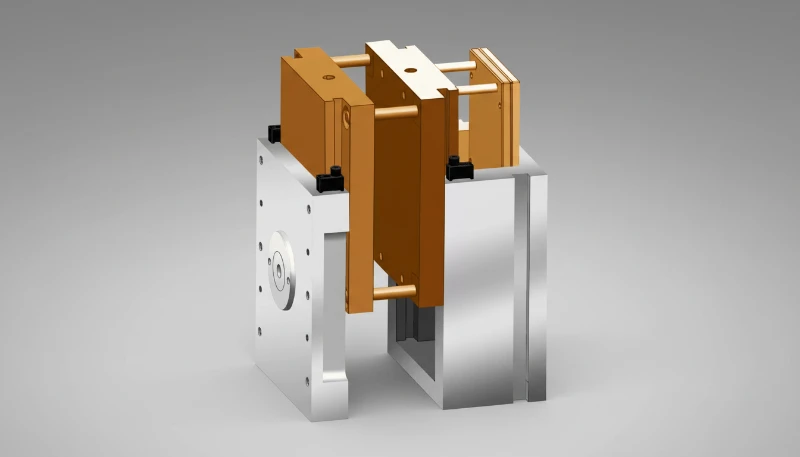
Извлечь пластиковую деталь из формы кажется просто, пока она не застрянет, не поцарапается или не деформируется. Разница между плавным извлечением и застреванием часто определяется одним решением при проектировании пресс-формы: углом уклона1. За более чем 20 лет изготовления деталей методом литья под давлением на заводе ZetarMold в Шанхае мы убедились, что правильный уклон экономит производственное время, сокращает брак и продлевает срок службы формы. В этом руководстве объясняется, как проектировать рабочие уклоны без лишних догадок.
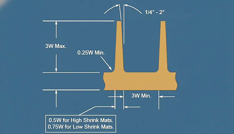
- Угол уклона — это наклон вертикальных стенок полости формы, обеспечивающий плавное извлечение детали
- Стандартный уклон составляет от 0.5° до 3° в зависимости от материала, качества поверхности и геометрии детали
- Текстурированные поверхности требуют уклона 3–7° — значительно больше, чем полированные
- Нулевой уклон возможен при использовании определённых материалов и конструкций формы, но сопряжён с производственными рисками
- Всегда исключайте угол уклона из измерений допусков детали, если прямо не указано иное
Что такое угол уклона при литье под давлением?
Угол уклона при литье под давлением определяется функциями, ограничениями и компромиссами, описанными в этом разделе. Если вы сравниваете поставщиков или планируете закупку, наше руководство по поиску поставщика литья под давлением охватывает подготовку RFQ, квалификацию и проверку коммерческих рисков.
Угол уклона — небольшой наклон вертикальных стенок полости и знака. Вместо параллельных стенок они отклоняются наружу на долю или несколько градусов, создавая зазор между затвердевшим пластиком и сталью при открытии.
Представьте форму для льда: благодаря уклону каждого гнезда кубики легко извлекаются. Без уклона форму пришлось бы скручивать, нагревать или выталкивать кубики силой. Тот же принцип действует при литье под давлением, но цена ошибки намного выше, когда прецизионные детали выпускаются серийно.
Уклоны предусмотрены с обеих сторон формы. Сторона матрицы (сторона A, или передняя полуформа) и сторона пуансона (сторона B, или задняя полуформа) имеют собственные уклоны. В формах с боковыми механизмами, например ползунами или наклонными толкателями, направление уклона соответствует движению этих боковых знаков, а не основной линии разъема.
На нашем заводе в Шанхае мы 20+ лет совершенствуем рекомендации по формовочным уклонам на основе тысяч проектов пресс-форм. Собственное производство выпускает 100+ комплектов пресс-форм в месяц, что даёт нам обширные практические данные о значениях уклона, действительно эффективных в серийном производстве.
Почему каждой литьевой пресс-форме требуется угол уклона?
В этом разделе рассматривается, нужен ли каждой пресс-форме угол уклона и как он влияет на стоимость, качество, сроки или риски при выборе поставщика. Без угла уклона пластиковая деталь при охлаждении и усадке создаёт вакуумное сцепление со стенкой пресс-формы. При раскрытии пресс-формы или срабатывании выталкивающих штифтов это сцепление приходится преодолевать силой, что приводит к задирам, царапинам, деформации или полному прилипанию детали.
Вот что происходит при недостаточном или отсутствующем уклоне:
Правильно спроектированный угол уклона устраняет эти проблемы, создавая небольшой зазор между деталью и стенкой формы в момент начала раскрытия. Деталь извлекается чисто, стабильно и без повреждений — цикл за циклом.
"Формовочного уклона 1° на сторону достаточно для большинства деталей с полированной поверхностью глубиной менее 50 mm."True
Для стандартных полированных поверхностей из распространенных конструкционных пластиков, таких как ABS или PP, уклон от 0.5° до 1° на сторону обеспечивает достаточное извлечение деталей глубиной до 50 mm. Более глубоким деталям или текстурированным поверхностям требуется больший уклон для компенсации увеличенной площади контакта.
"Литейные уклоны необходимы только на стороне A полости пресс-формы."False
Уклон требуется как со стороны полости, так и со стороны знака. Со стороны знака часто нужен больший уклон, поскольку при охлаждении пластик усаживается на него и удерживается плотнее, чем со стороны полости. Отсутствие уклона на знаке — распространённая причина проблем с выталкиванием.
Каковы стандартные значения угла уклона для разных материалов?
В этом разделе приведены основные категории и варианты стандартных углов уклона для разных материалов. Пластики различаются усадкой, коэффициентом трения и жесткостью, поэтому оптимальный угол уклона существенно зависит от материала. Ниже представлена практическая справочная таблица, основанная на опыте ZetarMold с 400+ материалами.
| Материал | Мин. уклон (полированная поверхность) | Рекомендуемый уклон | Примечания |
|---|---|---|---|
| ABS | 1° | 1–2° | Хорошая жёсткость; стандартный уклон работает хорошо |
| PC (поликарбонат) | 1° | 1.5–2° | Жесткий; более высокая усадка требует большего уклона |
| PP (полипропилен) | 0.5° | 0.5–1° | Гибкий; допускает меньшие значения уклона |
| PA6/PA66 (нейлон) | 0.5° | 0.5–1.5° | Низкое трение облегчает извлечение; для стеклонаполненных марок требуется 1–3° |
| PS (полистирол) | 2° | 2–3° | Хрупкий; для предотвращения растрескивания требуется больший уклон |
| POM (ацеталь) | 0.5° | 1–1.5° | Низкое трение, но высокая кристаллическая усадка |
| PMMA (акрил) | 1.5° | 2–3° | Прозрачный; легко царапается, требует большого уклона |
| ТПУ/ТПЭ | 0.5° | 0.5–1° | Эластичный; материал растягивается при выталкивании |
| Со стекловолокном (любым) | 1.5° | 2–3° | Абразивные волокна повышают трение о стенки формы |
Эти значения предполагают полированные поверхности формы. Для текстурированных поверхностей добавьте от 1° до 4° в зависимости от глубины текстуры; подробнее это рассмотрено ниже в разделе об отделке поверхности2. Главное: жесткие, хрупкие и стеклонаполненные материалы всегда требуют большего уклона, чем гибкие пластики с низким трением.
Как рассчитать требуемый угол уклона?
В этом разделе рассматривается расчет необходимого угла уклона и его влияние на стоимость, качество, сроки и риски при выборе поставщика. Хотя углы уклона часто выбирают по эмпирическим таблицам, для получения более точной исходной величины можно использовать простой геометрический расчет.
Основная формула связывает угол уклона (α), глубину детали (H) и разницу размеров между верхней и нижней частями наклонной стенки:
Формула: tan(α) = (D − d) / (2 × H)
Где α — угол уклона на сторону, D — больший размер (на линии разъёма), d — меньший размер (внизу хода извлечения), а H — полная глубина стенки.
Пример: Для легкого извлечения детали с глубиной стенки 60 мм нужен зазор 0,5 мм с каждой стороны. По формуле tan(α) = 0,5 / 60 = 0,0083, откуда α ≈ 0,48°. После округления получаем 0,5° на сторону — именно минимальное рекомендуемое значение для полированной детали из ПП такой глубины.
Наши 8 старших инженеров используют Moldflow simulation3 для моделирования и геометрическую формулу для проверки углов уклона до обработки стали. Благодаря 47 литьевым машинам от 90T до 1850T мы можем проверить выбранные уклоны в реальных испытаниях литья — этот этап пропускает большинство компаний, занимающихся только проектированием.
Какие факторы влияют на выбор угла уклона?
В этом разделе рассматриваются факторы выбора угла уклона и их влияние на стоимость, качество, сроки и риски снабжения. Помимо самого материала требуемый уклон определяется несколькими конструктивными и производственными факторами. Игнорирование любого из них может привести к производственным проблемам, исправление которых после изготовления формы обойдется дорого.
Глубина детали или высота стенки: Для глубокой вытяжки уклон подбирают особенно тщательно. Уклон 0,5° на стенке 10 мм дает зазор лишь 0,09 мм на сторону, а тот же уклон на стенке 100 мм — 0,87 мм, чего обычно достаточно. Чем глубже стенка, тем важнее уклон, хотя сам угол иногда может быть меньше.
Толщина стенки: Более толстые стенки сильнее усаживаются при охлаждении и плотнее охватывают пуансон. Если толщина превышает 3 мм, увеличьте уклон на 0,5°–1° относительно базовой рекомендации для материала.
Сторона пуансона и сторона матрицы: При охлаждении пластик усаживается на пуансон (сторона B), поэтому на этой стороне обычно требуется уклон на 0,5°–1° больше, чем со стороны матрицы. Это особенно важно для деталей с глубокими бобышками или ребрами, где пластик плотно охватывает сталь.
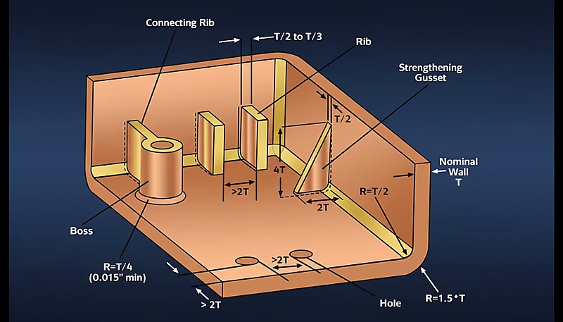
Ребра жесткости и бобышки: Для ребер высотой до 3 мм допустим уклон 0,5°, при высоте 3–5 мм — 1°, выше 5 мм — 1,5°. Для бобышек действует та же зависимость, но добавляют 0,5°, поскольку при охлаждении они усаживаются вокруг стержня.
"Для детали одной и той же геометрии текстурированные поверхности требуют большего угла формовочного уклона, чем полированные."True
Текстура поверхности создаёт микроскопические поднутрения, которые физически удерживают затвердевший пластик при выталкивании. Чем грубее текстура, тем больший уклон требуется, чтобы извлечь деталь без задиров.
"Угол уклона всегда следует включать в спецификацию размерных допусков детали."False
В стандартной практике проектирования пресс-форм угол уклона обычно рассматривается как особенность оснастки и извлечения, а не как обычный размерный допуск. Если уклон должен влиять на критический допуск, это необходимо явно указать при DFM.
Как текстура поверхности влияет на требования к уклону?
Отделка поверхности — один из самых недооценённых факторов проектирования уклона. Чисто декоративная на вид текстура создаёт микроподнутрения, сопротивляющиеся выталкиванию, и уклон должен компенсировать это механическое сцепление.
| Отделка поверхности | Глубина текстуры | Рекомендуемый уклон |
|---|---|---|
| Полированная (SPI A-1–A-3) | < 0,001 мм | 0.5°–1° |
| Мелкая матовая текстура (SPI B-1–B-3) | 0.001–0.01 mm | 1°–1.5° |
| Средняя текстура (MT11010) | 0.01–0.05 mm | 1.5°–3° |
| Грубая текстура (MT11020) | 0.05–0.1 mm | 3°–5° |
| Текстура кожи / глубокая текстура | 0.1–0.2+ mm | 5°–7°+ |
Практическое правило: на каждые 0.01 mm глубины текстуры добавляйте примерно 1° уклона. Таким образом, для текстуры глубиной 0.05 mm требуется около 5° уклона для беспрепятственного извлечения. Эта зависимость достаточно линейна для раннего DFM-анализа, даже до получения физических образцов текстуры от поставщика оснастки.
По этой причине в ZetarMold мы всегда уточняем требования к отделке поверхности на раннем этапе проектирования. Переход от полированной поверхности к текстуре под кожу в середине проекта может потребовать переработки всей схемы уклонов полости, что значительно проще выполнить до обработки стали, чем после нее.
Каких распространённых ошибок при выборе угла уклона следует избегать?
В этом разделе разобраны основные ошибки при выборе уклонов. За два десятилетия проверки тысяч конструкций форм на нашем заводе в Шанхае мы регулярно видим одни и те же ошибки. Они повышают брак, требуют дорогой доработки формы и задерживают производство, хотя их можно предотвратить грамотным планированием на этапе DFM. Ниже — частые ошибки и способы избежать их в следующем проекте.
Ошибка 1: нулевой уклон вертикальных стенок. Некоторые конструкторы считают, что жесткие допуски требуют нулевого уклона. На деле он почти гарантирует застревание, кроме случаев с гибкими материалами вроде ТПУ. Если необходим почти нулевой уклон, вместо прямой вертикальной стенки рассмотрите ступенчатую или смещенную линию разъема.
Ошибка 2: разные направления уклона. Все уклоны на одной стороне должны быть направлены одинаково — к линии разъема. Смешанные направления создают непредусмотренные поднутрения, полностью препятствующие извлечению; часто их трудно заметить в CAD до изготовления формы.
Ошибка 3: игнорирование усадки со стороны пуансона. При охлаждении пластик усаживается на пуансон. Если задать одинаковый уклон со стороны матрицы и пуансона, сопротивление извлечению на стороне пуансона будет значительно выше. Всегда добавляйте там 0,5°–1°, чтобы компенсировать усадочное обжатие.
Ошибка 4: неучтенные требования последующей обработки. Если после формования деталь будут сваривать ультразвуком, соединять защелками или обрабатывать резанием, уклон не должен мешать сопрягаемым поверхностям и элементам позиционирования. Одновременно учитывайте формование и сборку, чтобы избежать дорогой переработки конструкции и обеспечить беспроблемные последующие операции.
"Назначение технологического уклона с учетом глубины текстуры — надежная отправная точка для текстурированных поверхностей формы."True
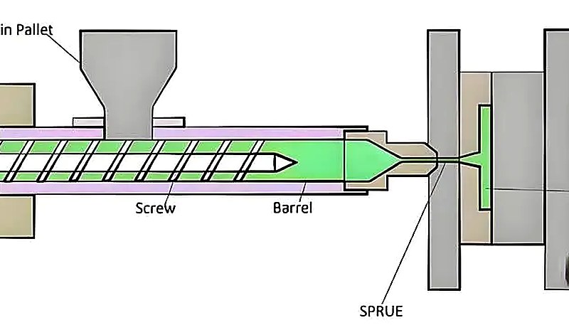
Схема литьевой машины для контекста оснастки
"Больший угол уклона всегда улучшает извлечение без недостатков."False
Чрезмерный уклон может изменить толщину стенки, посадку при сборке, внешний вид и характер соблюдения допусков. Уклон следует оптимизировать под деталь, а не бездумно увеличивать до максимума.
Работа с 400+ материалами в рамках систем качества ISO 9001 и ISO 13485 означает, что мы документировали результаты применения уклонов практически для каждого распространенного инженерного пластика. Наша база данных процессов помогает выявлять риски, связанные с уклонами, до завершения проектирования пресс-формы.
Как оптимизировать углы уклона для сложных деталей?
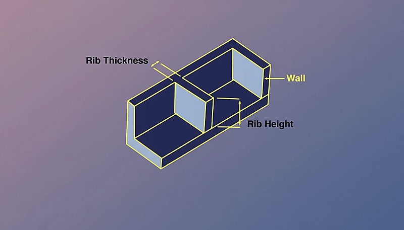
Детали простой формы с прямыми стенками не вызывают затруднений. Однако реальные детали, изготовленные литьём под давлением, имеют рёбра, бобышки, резьбы, поднутрения и защёлкивающиеся элементы, для каждого из которых действуют свои требования к формовочному уклону. Ниже описано, как справиться с этой сложностью, не ухудшая технологичность литья.
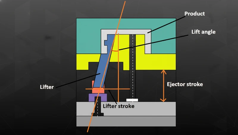
Детали с ползунами и наклонными толкателями: Уклон для бокового перемещения ориентируют по направлению ползуна, а не по основной линии разъема. На гранях ползуна задавайте не менее 3°, чтобы сталь отошла от пластика до отвода ползуна. Для наклонных толкателей уклон должен учитывать составной угол движения.
Глубокие детали: Для стенок глубже 100 мм используйте ступенчатый уклон: больший угол у линии разъема с уменьшением к дну. Это сохраняет равномерную толщину стенки и обеспечивает достаточный зазор для извлечения там, где он наиболее важен.
Многогнездные формы: Во всех гнездах задавайте одинаковые уклоны, чтобы силы извлечения и время цикла по всей форме были одинаковыми. Различия уклонов между гнездами часто вызывают трудно диагностируемый разброс качества в производстве.
Проверка моделированием: Перед утверждением сложной схемы уклонов выполните моделирование течения расплава и проверьте извлечение. MOLDFLOW и аналогичные программы прогнозируют места застревания, концентрацию сил извлечения и достаточность уклонов еще до обработки стали.
Как следует проектировать углы уклона?
В этом разделе рассматривается проектирование литейных уклонов и его влияние на стоимость, качество, сроки и риски закупки. Правильно спроектировать литейный уклон несложно, но необходимо учитывать детали: формуемый материал, требуемую отделку поверхности, глубину стенок и сложность геометрии детали. Правильный учет этих факторов обеспечивает чистое извлечение деталей, увеличивает срок службы пресс-форм и снижает производственные затраты.
В ZetarMold наша инженерная команда применяет более чем 20-летний опыт проектирования форм в каждом проекте — от простых двухплитных до сложных многоползунных конструкций. Если вы разрабатываете новую деталь и хотите получить экспертную оценку углов уклона или другого решения по форме, мы готовы помочь.
Часто задаваемые вопросы
Каков минимальный угол конусности для литья под давлением?
Абсолютный минимальный угол уклона составляет 0.5° на сторону для гибких материалов, таких как PP или TPU, при полированных поверхностях пресс-формы. Для жестких инженерных пластиков, таких как ABS или PC, следует начинать как минимум с 1°. Меньшие значения создают риск прилипания детали, царапания поверхности и нестабильного усилия выталкивания, которое со временем может повредить и деталь, и пресс-форму. Для текстурированных или зернистых поверхностей всегда предусматривайте больший уклон; также увеличивайте угол для деталей с глубокими стенками или сложной геометрией. В серийном производстве стоимость добавления еще 0.5° уклона ничтожна по сравнению со стоимостью устранения проблемы застревания детали после изготовления пресс-формы.
Можно ли выполнять литье под давлением без угла наклона?
Да, но только в очень специфических случаях — обычно с гибкими материалами, такими как TPU или силикон, способными растягиваться и сжиматься при выталкивании без остаточной деформации. Даже тогда нулевой уклон значительно увеличивает усилие выталкивания, разброс времени цикла и долю дефектов. В большинстве производственных форм абсолютный минимум уклона составляет 0.25°–0.5°, даже если номинально деталь требует нулевого уклона. Если конструкция действительно не допускает конусности, рассмотрите складные сердечники, разъёмные гнёзда или небольшое смещение линии разъёма для создания направленного зазора при извлечении.
Как угол уклона влияет на допуск детали?
Угол уклона обычно исключается из поля допуска детали: размеры измеряются в заданной нейтральной плоскости или относительно базы, а не по самим наклонным стенкам. Это стандартная практика, установленная ISO 8062 и большинством применяемых в отрасли справочников по проектированию пресс-форм. Если в вашем случае необходимо включить уклон в поле допуска, что встречается редко и обычно ограничивается прецизионными медицинскими или оптическими компонентами, это должно быть явно указано на чертеже детали. Для большинства деталей, изготовленных литьем под давлением, уклон не влияет на важные функциональные размеры.
Какой угол уклона требуется для текстурированных поверхностей?
Текстурированным поверхностям требуется значительно больший уклон, чем полированным, поскольку текстурный рисунок создаёт микроскопические поднутрения, которые удерживают пластиковую деталь при выталкивании. Практическое правило: добавляйте примерно 1° уклона на каждые 0.01 mm глубины текстуры. Для мелкой матовой текстуры глубиной около 0.01 mm требуется уклон примерно 1°–1.5°, для средней текстуры — 1.5°–3°, а для глубокой текстуры под кожу глубиной более 0.1 mm — 5°–7° и более. Всегда сверяйтесь с рекомендациями конкретного поставщика текстуры, поскольку разные процессы текстурирования могут требовать разных уклонов при одинаковом внешнем виде.
Как добавить черновик к существующей детали в дизайне?
В большинстве CAD-систем уклон можно задать как параметрический элемент, наклоняющий выбранные грани на заданный угол относительно нейтральной плоскости или линии разъёма. Для сложных деталей добавляйте уклон поэтапно: начните со стенок со стороны сердечника, затем обработайте стенки со стороны полости, после чего — рёбра, бобышки и другие вторичные элементы. Убедитесь, что все направления уклона согласованы и направлены к линии разъёма. Если оснастка уже изготовлена и обнаружен недостаточный уклон, для его увеличения потребуется наплавка и повторная механическая обработка соответствующих поверхностей полости, что дорого и занимает много времени. Это ещё одна причина правильно задать уклон с первого раза.
Нужен ли больший угол съема на стороне сердечника, чем на стороне полости?
Да, в большинстве случаев на стороне сердечника полезен дополнительный уклон. Поскольку пластик при охлаждении в цикле литья усаживается на сердечник, эта сторона испытывает значительно большее трение и усилие сцепления при выталкивании. Стандартная практика проектирования форм — добавлять на стороне сердечника уклон на 0.5°–1° больше, чем на стороне полости. Эта разница особенно важна для деталей глубокой вытяжки, компонентов с высокими бобышками и деталей с плотной сеткой рёбер, где суммарное усилие усадки концентрируется на стали сердечника.
угол уклона: угол уклона — это конусность, которая помогает снять отформованные стенки с матрицы или пуансона без задиров, царапин и деформации детали. ↩
отделка поверхности: Отделка поверхности — качество текстуры полости формы, напрямую влияющее на трение при извлечении: чем глубже текстура, тем больший уклон нужен для чистого извлечения детали. ↩
Моделирование Moldflow: Moldflow — инструмент моделирования литья под давлением, прогнозирующий заполнение, охлаждение и силы извлечения и позволяющий оптимизировать уклон до изготовления оснастки. ↩