tan(α) = (D − d) / (2 × H) 射出成形金型設計 decision: 抜き勾配1. In our 20+ years of building parts through the 射出成形プロセス 射出成形金型のドラフト角度を設計する方法は? | ZetarMold

- A draft angle is the taper applied to vertical walls of a mold cavity to allow smooth part removal
- Standard draft ranges from 0.5° to 3° depending on material, surface finish, and part geometry
- Textured surfaces require 3–7° of draft—significantly more than polished surfaces
- Zero draft is possible with specific materials and mold designs, but it carries production risks
- Always exclude draft angle from part tolerance measurements unless explicitly specified otherwise
What Is a Draft Angle in Injection Molding?
A draft angle in injection molding is defined by the function, constraints, and tradeoffs explained in this section. If you are comparing vendors or planning procurement, our injection molding supplier sourcing guide covers RFQ prep, qualification, and commercial risk checks.
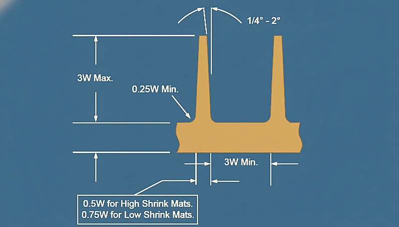
A draft angle is the slight taper—or slope—designed into the vertical walls of a mold cavity and core. Instead of perfectly parallel sidewalls, the cavity walls lean outward by a fraction of a degree to several degrees, creating clearance between the solidified plastic and the steel as the mold opens.
Think of it like an ice cube tray: the tapered shape of each compartment lets you pop the cubes out easily. Without that taper, you’d need to twist, heat, or force the cubes out. The same principle applies to injection molding—except the stakes are much higher when you’re producing precision parts at scale.
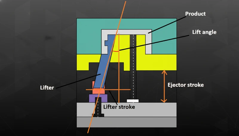
Draft angles exist on both sides of the mold. The cavity side (A-side, or front mold) and the core side (B-side, or rear mold) each have their own draft. For molds with side actions—such as sliders or lifters—the draft direction follows the movement of those side cores rather than the main parting line.
At our Shanghai factory, we’ve spent 20+ years refining draft angle guidelines across thousands of mold designs. Our in-house mold manufacturing facility produces 100+ mold sets per month, giving us extensive real-world data on what draft values actually work in production.
Why Does Every Injection Mold Need a Draft Angle?
このセクションは、すべての射出成形金型に抜き勾配が必要かどうかと、コスト、品質、納期、または調達リスクへの影響について説明します。抜き勾配がないと、プラスチック部品は冷却と収縮時に金型壁に対して真空シールを形成します。金型が開いたり、エジェクタピンが押したりするとき、そのシールは力で破られなければならず、引っかき傷、スコアリング、変形、または完全な詰まりを引き起こします。
Here’s what happens when draft is insufficient or missing:
A properly designed draft angle eliminates these problems by creating a small gap between the part and mold wall the instant the mold begins to open. The part releases cleanly, consistently, and without damage—cycle after cycle.
“A draft angle of 1° per side is sufficient for most polished-surface parts under 50 mm in depth.”真
For standard polished surfaces with common engineering plastics like ABS or PP, 0.5° to 1° per side provides adequate release clearance for parts up to 50 mm deep. Deeper parts or textured surfaces need more draft to compensate for increased surface contact area.
“Draft angles are only necessary on the cavity A-side of the mold.”偽
Draft is required on both the cavity and core sides. The core side often needs more draft because the plastic shrinks onto it during cooling, creating a tighter grip than on the cavity side. Skipping draft on the core is a common cause of ejection failures.
What Are the Standard Draft Angle Values by Material?
The standard draft angle values by material are the main categories or options explained in this section. Different plastics have different shrinkage rates, friction coefficients, and stiffness levels—which means the ideal draft angle varies significantly by material. Here’s a practical reference table based on our experience across 400+ materials at ZetarMold.
| 素材 | Min Draft (Polished) | Recommended Draft | 備考 |
|---|---|---|---|
| ABS | 1° | 1–2° | Good stiffness; standard draft works well |
| PC(ポリカーボネート) | 1° | 1.5–2° | Rigid; higher shrinkage needs more draft |
| PP(ポリプロピレン) | 0.5° | 0.5–1° | Flexible; can use lower draft values |
| PA6/PA66 (Nylon) | 0.5° | 0.5–1.5° | Low friction helps; glass-filled needs 1–3° |
| PS(ポリスチレン) | 2° | 2–3° | Brittle; needs more draft to prevent cracking |
| POM (Acetal) | 0.5° | 1–1.5° | Low friction, but high crystalline shrinkage |
| PMMA (Acrylic) | 1.5° | 2–3° | Transparent; scratches easily, needs generous draft |
| TPU/TPE | 0.5° | 0.5–1° | Elastic; material stretches during ejection |
| Glass-filled (any) | 1.5° | 2–3° | Abrasive fibers increase friction on mold walls |
These values assume polished mold surfaces. For textured finishes, add 1° to 4° depending on texture depth—a topic we’ll cover in detail in the 表面仕上げ2 section below. The key takeaway: rigid, brittle, and glass-filled materials always demand more draft than flexible, low-friction plastics.
How Do You Calculate the Required Draft Angle?
このセクションは、必要な抜き勾配の計算と、コスト、品質、納期、または調達リスクへの影響について説明します。抜き勾配は経験に基づく表から選ばれることが多いですが、より正確な出発点が必要な場合に使用できる、簡単な幾何学的計算があります。
The fundamental formula relates draft angle (α), part depth (H), and the size difference between the top and bottom of the drafted wall:
tan(α) = (D − d) / (2 × H)
「より大きな抜き勾配は、常に欠点なく優れた排出結果をもたらします。」
例 A part with 60 mm wall depth needs to clear 0.5 mm per side for easy release. Using the formula: tan(α) = 0.5 / 60 = 0.0083, which gives α ≈ 0.48°. Rounded up, that’s 0.5° per side—exactly the minimum recommended for a polished PP part at that depth.
Our 8 senior engineers use Moldflow simulation3 alongside the geometric formula to verify draft angles before cutting steel. With 47 injection molding machines from 90T to 1850T, we can validate draft choices through actual molding trials—a step most design-only firms skip.

What Factors Influence Draft Angle Selection?
このセクションは、抜き勾配の選択に影響を与える要因と、コスト、品質、納期、または調達リスクへの影響について説明します。材料自体以外にも、いくつかの設計および生産要因が、必要な抜き勾配の量を決定します。これらのいずれかを無視すると、金型製作後に修正するのに高額な費用がかかる生産上の問題を引き起こす可能性があります。
Part depth or wall height: Deeper draws require careful draft selection. A 0.5° draft on a 10 mm wall creates only 0.09 mm of clearance per side—but the same 0.5° on a 100 mm wall gives 0.87 mm, which is usually sufficient. As a rule, the deeper the wall, the more critical draft becomes, even though the angle itself can sometimes be smaller.
肉厚: Thicker walls shrink more during cooling, pulling tighter against the core. If your wall thickness exceeds 3 mm, consider increasing draft by 0.5° to 1° above the material’s baseline recommendation.
Core vs. cavity side: Plastic shrinks onto the core (B-side) during cooling, so the core side generally needs 0.5° to 1° more draft than the cavity side. This is especially important for parts with deep bosses or ribs where the plastic wraps tightly around the steel.
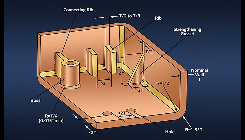
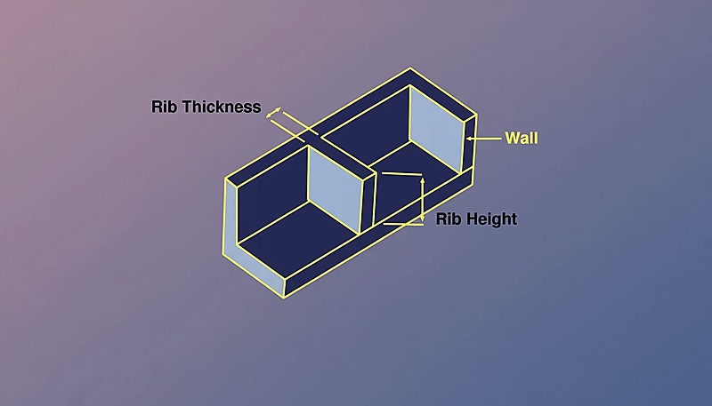
Reinforcing ribs and bosses: Ribs under 3 mm tall can use 0.5° draft. Between 3–5 mm, use 1°. Above 5 mm, allow 1.5°. Bosses follow the same progression but add 0.5° because they shrink around the core pin during cooling.
“Textured surfaces require larger draft angles than polished surfaces for the same part geometry.”真
Surface texture creates microscopic undercuts that physically grip the solidified plastic during ejection. The rougher the texture, the more draft is needed to release the part without dragging.
“The draft angle should always be included in the part dimensional tolerance specification.”偽
In standard mold design practice, draft angle is usually treated as a tooling and release feature rather than a normal dimensional tolerance. If draft must affect a critical tolerance, it should be explicitly marked during DFM.
How Do Surface Textures Affect Draft Requirements?
Surface finish is one of the most underestimated factors in draft angle design. A texture that looks purely cosmetic actually creates tiny undercuts that resist ejection—and the draft must compensate for this mechanical interlock.
| 表面仕上げ | Texture Depth | Recommended Draft |
|---|---|---|
| Polished (SPI A-1 to A-3) | < 0.001 mm | 0.5°–1° |
| Fine matte (SPI B-1 to B-3) | 0.001–0.01 mm | 1°–1.5° |
| Medium texture (MT11010) | 0.01–0.05 mm | 1.5°–3° |
| Coarse texture (MT11020) | 0.05–0.1 mm | 3°–5° |
| Leather grain / deep texture | 0.1–0.2+ mm | 5°–7°+ |
実用的な経験則:テクスチャーの深さ0.01 mmごとに、約1°の抜き勾配を追加します。したがって、深さ0.05 mmのテクスチャーは、きれいに離型するために約5°の抜き勾配が必要です。この関係は線形性が十分にあり、金型サプライヤーから物理的なテクスチャーサンプルが入手できる前の、初期段階のDFMレビューでも有用です。

This is one reason we always ask about surface finish early in the design process at ZetarMold. Changing from polished to leather grain midway through a project can require redesigning the entire cavity’s draft scheme—which is far easier to do before steel is cut than after.
What Are the Common Draft Angle Mistakes to Avoid?
避けるべき一般的な抜き勾配の間違いは、このセクションで説明されている主なカテゴリーまたはオプションです。上海工場での20年にわたる数千の金型設計をレビューした結果、同じ抜き勾配の間違いが繰り返し見られます。これらの誤りは、不良率の増加、高額な金型修正、およびDFM段階での適切な計画により回避できたはずの生産遅延を引き起こします。以下は最も一般的な間違いと、次のプロジェクトでそれらを回避する方法です。
Mistake 1: Zero draft on vertical walls. Some designers assume that tight tolerances require zero draft. In reality, zero draft virtually guarantees sticking unless you’re working with flexible materials like TPU. If you absolutely need near-zero draft, consider using a stepped or offset parting line instead of a straight vertical wall.
Mistake 2: Inconsistent draft direction. All draft angles on a given side should lean in the same direction—toward the parting line. Mixed draft directions create unintended undercuts that prevent ejection entirely, and they’re often hard to spot in CAD until the mold is built.
Mistake 3: Ignoring shrinkage effects on the core side. Plastic shrinks onto the core during cooling. If you use the same draft on both cavity and core, the core side will have significantly more ejection resistance. Always give the core side an extra 0.5°–1° of draft to account for this shrinkage grip.
Mistake 4: Forgetting post-processing requirements. 部品が成形後に超音波溶着、スナップフィット、または機械加工される場合、抜き勾配は嵌合面や位置決め機能を妨げてはなりません。コストのかかる再設計を避け、下流工程を円滑に進めるため、成形と組立の両方の観点から同時に抜き勾配を計画してください。
“Adding draft for texture depth is a reliable starting point for textured mold surfaces.”真
A common shop rule is to increase draft as texture becomes deeper, then verify the value against the texture supplier data and the actual release direction. This prevents dragging and scuffing on cosmetic surfaces.
“A larger draft angle always produces better ejection results with no downsides.”偽
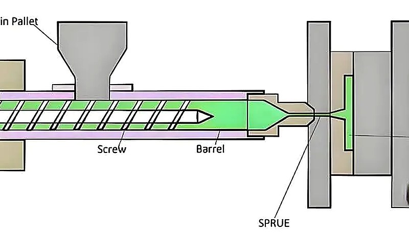
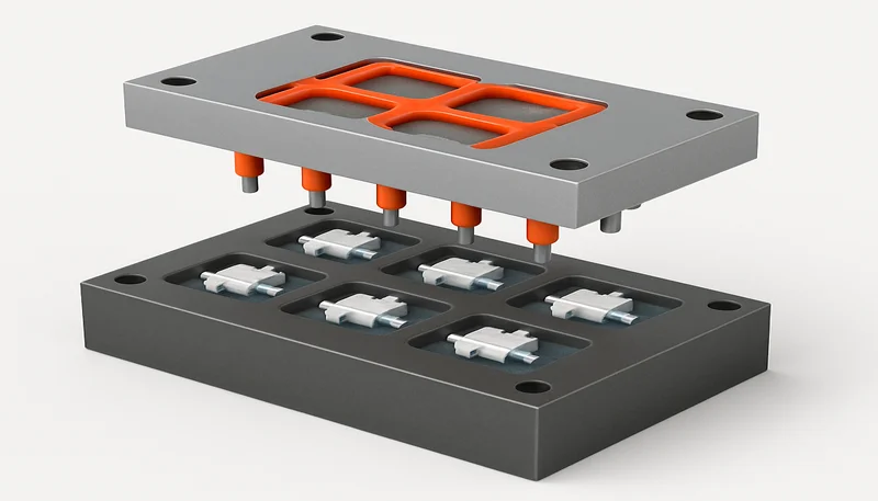
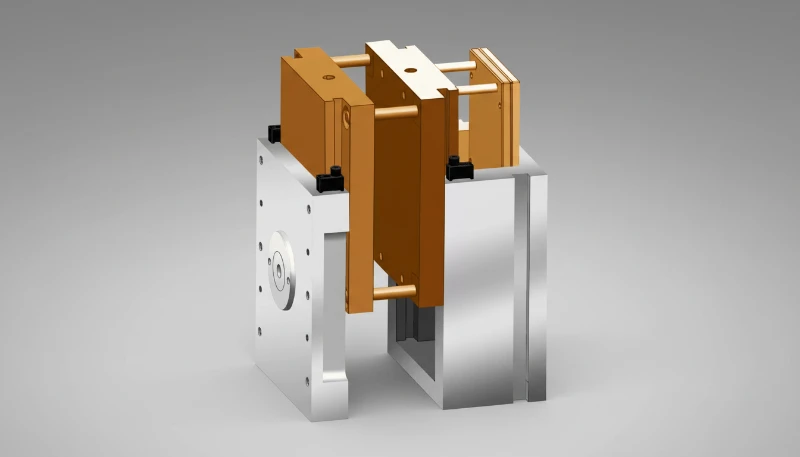
金型コンテキスト用射出成形機概略図
Working across 400+ materials under ISO 9001 and ISO 13485 quality systems means we’ve documented draft angle outcomes for virtually every common engineering plastic. Our process database helps us flag draft-related risks before the mold design is finalized.
How Do You Optimize Draft Angles for Complex Parts?

Simple parts with straight walls are straightforward. But real-world injection molded parts have ribs, bosses, threads, undercuts, and snap features—each with their own draft requirements. Here’s how to handle the complexity without sacrificing moldability.
Parts with sliders and lifters: Side-action draft follows the slider’s movement direction, not the main parting line. Use 3° minimum on slider faces to ensure the steel clears the plastic before the slider retracts. For angled lifters, the draft must account for the lifter’s compound angle of motion.
Deep-draw parts: For walls deeper than 100 mm, consider using a stepped draft—starting with a larger angle near the parting line and tapering to a smaller angle at the bottom. This maintains wall thickness uniformity while still providing adequate release clearance where it matters most.
Multi-cavity molds: Ensure all cavities use the same draft values to maintain consistent ejection forces and cycle times across the entire mold. Uneven draft between cavities is a common source of cavity-to-cavity quality variation that can be difficult to diagnose in production.
Simulation verification: Before finalizing any complex draft scheme, run a mold flow simulation to check for ejection issues. Tools like MOLDFLOW can predict where the part will stick, where ejection forces concentrate, and whether the draft is sufficient—all before any steel is cut.
抜き勾配設計にはどのように取り組むべきですか?
このセクションは、抜き勾配設計へのアプローチと、コスト、品質、納期、または調達リスクへの影響について説明します。適切な抜き勾配を設計することは複雑ではありませんが、細部への注意が必要です:成形する材料、必要な表面仕上げ、壁の深さ、部品形状の複雑さ。これらの要因を適切に設定すれば、部品はきれいに離型し、金型の寿命は長くなり、生産コストは削減されます。
At ZetarMold, our engineering team brings 20+ years of mold design experience to every project—from simple two-plate tools to complex multi-slide molds. If you’re designing a new part and want expert feedback on your draft angles (or any other mold design decision), we’re here to help.
よくある質問
What Is the Minimum Draft Angle for Injection Molding?
The absolute minimum draft angle is 0.5° per side for flexible materials like PP or TPU with polished mold surfaces. For rigid engineering plastics like ABS or PC, start at 1° minimum. Going below these values risks part sticking, surface scraping, and inconsistent ejection forces that can damage both the part and the mold over time. Always add more draft for textured or grained surfaces, and consider increasing the angle if your part has deep walls or complex geometry. In production environments, the cost of adding an extra 0.5° of draft is negligible compared to the cost of fixing a stuck-part problem after the mold is built.
Can You Injection Mold Without a Draft Angle?
Yes, but only in very specific cases—typically with flexible materials like TPU or silicone that can stretch and compress during ejection without permanent deformation. Even then, zero draft increases ejection force, cycle time variability, and defect rates significantly. Most production molds use at least 0.25°–0.5° of draft as an absolute minimum, even for parts that nominally require zero draft. If your design truly cannot tolerate any taper, consider alternative strategies like collapsible cores, split cavities, or a slight offset in the parting line to create directional release clearance.
How Does Draft Angle Affect Part Tolerance?
Draft angle is normally excluded from the part tolerance zone—dimensions are measured at a specified neutral plane or datum, not at the tapered walls themselves. This is standard practice established by ISO 8062 and most mold design handbooks used across the industry. If your application requires draft to be included in the tolerance zone (which is rare and usually limited to precision medical or optical components), it must be explicitly called out on the part drawing. For most injection molded parts, the draft taper is transparent to the functional dimensions that matter.
What Draft Angle Is Needed for Textured Surfaces?
Textured surfaces need significantly more draft than polished ones because the texture pattern creates microscopic undercuts that grip the plastic part during ejection. As a practical rule, add approximately 1° of draft for every 0.01 mm of texture depth. Fine matte textures around 0.01 mm depth need about 1°–1.5°, medium textures need 1.5°–3°, and deep leather grains exceeding 0.1 mm depth require 5°–7° or more. Always consult your texture supplier’s specific recommendation sheet, as different texturing processes can have different draft requirements for the same visual appearance.
How Do You Add Draft to an Existing Part Design?
In most CAD systems, you can apply draft as a parametric feature that tilts selected faces by a specified angle around a neutral plane or parting line. For complex parts, apply draft in stages—start with core-side walls, then cavity-side walls, followed by ribs, bosses, and other secondary features. Verify that all draft directions are consistent and point toward the parting line. If the part has already been tooled and you discover insufficient draft, increasing it requires welding and re-machining the affected cavity surfaces, which is expensive and time-consuming—another reason to get draft right the first time.
Does the Core Side Need More Draft Than the Cavity Side?
Yes, in most cases the core side benefits from additional draft. Because plastic shrinks onto the core during the cooling phase of the injection molding cycle, the core side experiences significantly more friction and gripping force during ejection. Adding 0.5°–1° more draft on the core side compared to the cavity side is standard mold design practice. This difference is especially important for deep-draw parts, components with tall bosses, and parts featuring dense rib patterns where the combined shrinkage force concentrates on the core steel.
-
draft angle: draft angle refers to is the taper that helps molded walls release from the cavity or core without dragging, scratching, or deforming the part. ↩
-
surface finish: 表面仕上げとは、離型摩擦に直接影響する金型キャビティ表面のテクスチャー品質を指し、深いテクスチャーほど、部品をきれいに離型するためにより大きな抜き勾配が必要です。 ↩
-
Moldflow simulation: Moldflowシミュレーションは、射出成形シミュレーションツールであり、充填パターン、冷却挙動、および離型力を予測し、金型製造前に抜き勾配の最適化を可能にします。 ↩